EP1185771B1 - Method of reducing emissions in the exhaust gases of an internal combustion engine - Google Patents
Method of reducing emissions in the exhaust gases of an internal combustion engine Download PDFInfo
- Publication number
- EP1185771B1 EP1185771B1 EP00941074A EP00941074A EP1185771B1 EP 1185771 B1 EP1185771 B1 EP 1185771B1 EP 00941074 A EP00941074 A EP 00941074A EP 00941074 A EP00941074 A EP 00941074A EP 1185771 B1 EP1185771 B1 EP 1185771B1
- Authority
- EP
- European Patent Office
- Prior art keywords
- internal combustion
- combustion engine
- generator
- crankshaft
- electric motor
- Prior art date
- Legal status (The legal status is an assumption and is not a legal conclusion. Google has not performed a legal analysis and makes no representation as to the accuracy of the status listed.)
- Expired - Lifetime
Links
Images

Classifications
-
- F—MECHANICAL ENGINEERING; LIGHTING; HEATING; WEAPONS; BLASTING
- F02—COMBUSTION ENGINES; HOT-GAS OR COMBUSTION-PRODUCT ENGINE PLANTS
- F02D—CONTROLLING COMBUSTION ENGINES
- F02D13/00—Controlling the engine output power by varying inlet or exhaust valve operating characteristics, e.g. timing
- F02D13/02—Controlling the engine output power by varying inlet or exhaust valve operating characteristics, e.g. timing during engine operation
- F02D13/0203—Variable control of intake and exhaust valves
-
- F—MECHANICAL ENGINEERING; LIGHTING; HEATING; WEAPONS; BLASTING
- F02—COMBUSTION ENGINES; HOT-GAS OR COMBUSTION-PRODUCT ENGINE PLANTS
- F02D—CONTROLLING COMBUSTION ENGINES
- F02D13/00—Controlling the engine output power by varying inlet or exhaust valve operating characteristics, e.g. timing
- F02D13/02—Controlling the engine output power by varying inlet or exhaust valve operating characteristics, e.g. timing during engine operation
- F02D13/0203—Variable control of intake and exhaust valves
- F02D13/0215—Variable control of intake and exhaust valves changing the valve timing only
-
- F—MECHANICAL ENGINEERING; LIGHTING; HEATING; WEAPONS; BLASTING
- F02—COMBUSTION ENGINES; HOT-GAS OR COMBUSTION-PRODUCT ENGINE PLANTS
- F02D—CONTROLLING COMBUSTION ENGINES
- F02D13/00—Controlling the engine output power by varying inlet or exhaust valve operating characteristics, e.g. timing
- F02D13/02—Controlling the engine output power by varying inlet or exhaust valve operating characteristics, e.g. timing during engine operation
- F02D13/0242—Variable control of the exhaust valves only
- F02D13/0249—Variable control of the exhaust valves only changing the valve timing only
-
- F—MECHANICAL ENGINEERING; LIGHTING; HEATING; WEAPONS; BLASTING
- F02—COMBUSTION ENGINES; HOT-GAS OR COMBUSTION-PRODUCT ENGINE PLANTS
- F02D—CONTROLLING COMBUSTION ENGINES
- F02D13/00—Controlling the engine output power by varying inlet or exhaust valve operating characteristics, e.g. timing
- F02D13/02—Controlling the engine output power by varying inlet or exhaust valve operating characteristics, e.g. timing during engine operation
- F02D13/0253—Fully variable control of valve lift and timing using camless actuation systems such as hydraulic, pneumatic or electromagnetic actuators, e.g. solenoid valves
-
- F—MECHANICAL ENGINEERING; LIGHTING; HEATING; WEAPONS; BLASTING
- F02—COMBUSTION ENGINES; HOT-GAS OR COMBUSTION-PRODUCT ENGINE PLANTS
- F02D—CONTROLLING COMBUSTION ENGINES
- F02D29/00—Controlling engines, such controlling being peculiar to the devices driven thereby, the devices being other than parts or accessories essential to engine operation, e.g. controlling of engines by signals external thereto
- F02D29/06—Controlling engines, such controlling being peculiar to the devices driven thereby, the devices being other than parts or accessories essential to engine operation, e.g. controlling of engines by signals external thereto peculiar to engines driving electric generators
-
- F—MECHANICAL ENGINEERING; LIGHTING; HEATING; WEAPONS; BLASTING
- F02—COMBUSTION ENGINES; HOT-GAS OR COMBUSTION-PRODUCT ENGINE PLANTS
- F02D—CONTROLLING COMBUSTION ENGINES
- F02D41/00—Electrical control of supply of combustible mixture or its constituents
- F02D41/02—Circuit arrangements for generating control signals
- F02D41/021—Introducing corrections for particular conditions exterior to the engine
- F02D41/0235—Introducing corrections for particular conditions exterior to the engine in relation with the state of the exhaust gas treating apparatus
- F02D41/024—Introducing corrections for particular conditions exterior to the engine in relation with the state of the exhaust gas treating apparatus to increase temperature of the exhaust gas treating apparatus
-
- F—MECHANICAL ENGINEERING; LIGHTING; HEATING; WEAPONS; BLASTING
- F02—COMBUSTION ENGINES; HOT-GAS OR COMBUSTION-PRODUCT ENGINE PLANTS
- F02D—CONTROLLING COMBUSTION ENGINES
- F02D41/00—Electrical control of supply of combustible mixture or its constituents
- F02D41/02—Circuit arrangements for generating control signals
- F02D41/04—Introducing corrections for particular operating conditions
- F02D41/06—Introducing corrections for particular operating conditions for engine starting or warming up
- F02D41/062—Introducing corrections for particular operating conditions for engine starting or warming up for starting
- F02D41/064—Introducing corrections for particular operating conditions for engine starting or warming up for starting at cold start
-
- B—PERFORMING OPERATIONS; TRANSPORTING
- B60—VEHICLES IN GENERAL
- B60W—CONJOINT CONTROL OF VEHICLE SUB-UNITS OF DIFFERENT TYPE OR DIFFERENT FUNCTION; CONTROL SYSTEMS SPECIALLY ADAPTED FOR HYBRID VEHICLES; ROAD VEHICLE DRIVE CONTROL SYSTEMS FOR PURPOSES NOT RELATED TO THE CONTROL OF A PARTICULAR SUB-UNIT
- B60W2710/00—Output or target parameters relating to a particular sub-units
- B60W2710/06—Combustion engines, Gas turbines
- B60W2710/0616—Position of fuel or air injector
- B60W2710/0622—Air-fuel ratio
-
- F—MECHANICAL ENGINEERING; LIGHTING; HEATING; WEAPONS; BLASTING
- F02—COMBUSTION ENGINES; HOT-GAS OR COMBUSTION-PRODUCT ENGINE PLANTS
- F02D—CONTROLLING COMBUSTION ENGINES
- F02D13/00—Controlling the engine output power by varying inlet or exhaust valve operating characteristics, e.g. timing
- F02D13/02—Controlling the engine output power by varying inlet or exhaust valve operating characteristics, e.g. timing during engine operation
- F02D2013/0292—Controlling the engine output power by varying inlet or exhaust valve operating characteristics, e.g. timing during engine operation in the start-up phase, e.g. for warming-up cold engine or catalyst
-
- F—MECHANICAL ENGINEERING; LIGHTING; HEATING; WEAPONS; BLASTING
- F02—COMBUSTION ENGINES; HOT-GAS OR COMBUSTION-PRODUCT ENGINE PLANTS
- F02D—CONTROLLING COMBUSTION ENGINES
- F02D41/00—Electrical control of supply of combustible mixture or its constituents
- F02D41/0002—Controlling intake air
- F02D2041/001—Controlling intake air for engines with variable valve actuation
-
- Y—GENERAL TAGGING OF NEW TECHNOLOGICAL DEVELOPMENTS; GENERAL TAGGING OF CROSS-SECTIONAL TECHNOLOGIES SPANNING OVER SEVERAL SECTIONS OF THE IPC; TECHNICAL SUBJECTS COVERED BY FORMER USPC CROSS-REFERENCE ART COLLECTIONS [XRACs] AND DIGESTS
- Y02—TECHNOLOGIES OR APPLICATIONS FOR MITIGATION OR ADAPTATION AGAINST CLIMATE CHANGE
- Y02T—CLIMATE CHANGE MITIGATION TECHNOLOGIES RELATED TO TRANSPORTATION
- Y02T10/00—Road transport of goods or passengers
- Y02T10/10—Internal combustion engine [ICE] based vehicles
- Y02T10/12—Improving ICE efficiencies
Definitions
- the present invention relates to a method of reducing emissions in the exhaust gases of an internal combustion engine which comprises at least one cylinder to which an air/fuel mixture is supplied when a crankshaft of the internal combustion engine is to be made to rotate, at least one intake valve, at least one exhaust valve, and a piston reciprocating between a top dead-centre position and a bottom dead-centre position in the cylinder.
- Emissions present in the exhaust gases include inter alia carbon monoxide CO, hydrocarbon compounds HC and nitrogen oxides NOx.
- the internal combustion engine is provided with a catalytic converter which, by means of a chemical reaction, burns these undesirable emissions completely.
- the chemical reaction in the catalytic converter occurs only when the catalytic converter has reached a predetermined working temperature which is reached after a predetermined operating time of the internal combustion engine. When the engine is cold-started, there is therefore no reduction of the abovementioned undesirable emissions in the catalytic converter.
- the fuel supplied from a fuel injection valve can be controlled accurately by means of the fuel injection system of the internal combustion engine in order thus to obtain an essentially constant lambda value for the air/fuel mixture supplied.
- the internal combustion engine is cold, however, fuel will condense on the comparatively cold walls in the intake duct and in the cylinder.
- the fuel condensed on the walls will be vaporized during idle running and accompany the air/fuel mixture which is flowing in the intake duct and being supplied to the cylinder space. If the vaporization of the fuel condensed on the walls is uneven, on account of pressure variations, temperature gradients, or the flow rate of the air/fuel mixture in the intake duct, a variation of the lambda value of the air/fuel mixture supplied to the cylinder space will occur.
- the speed of the internal combustion engine means the speed of rotation of the crankshaft of the internal combustion engine.
- the pressure in the intake duct will also vary, which in turn leads to the vaporization of the condensed fuel varying, so that a variation of the lambda value of the air/fuel mixture supplied to the cylinder space occurs.
- the uneven speed of the internal combustion engine is thus intensified.
- the object of the present invention is to reduce carbon monoxide CO, hydrocarbon compounds HC and nitrogen oxides NOx in exhaust gases from an internal combustion engine when cold-started.
- Another object of the invention is to make it possible for an internal combustion engine to work with a lean air/fuel mixture.
- a further object of the invention is to reach the working temperature of the catalytic converter as rapidly as possible.
- the internal combustion engine By supplying an air/fuel mixture greater than 1 to the cylinder, the abovementioned undesirable emissions in the exhaust gases emitted from the internal combustion engine are reduced.
- the internal combustion engine By means of the combined electric motor/generator, the internal combustion engine will work at an essentially constant speed during idle running.
- the exhaust valve By controlling the exhaust valve so that it opens before the piston has passed the bottom dead-centre position, the expansion stroke of the piston in the cylinder is interrupted, and very hot gases flow out through the exhaust duct and on to the catalytic converter which will thus be heated rapidly.
- Fig. 1 shows an internal combustion engine 1 which comprises at least one cylinder 2 to which an air/fuel mixture is supplied when a crankshaft 3 of the internal combustion engine 1 is to be made to rotate.
- At least one intake duct 4 is arranged so as to open and close intake ducts 5 which are connected to the cylinder 2 and through which an air/fuel mixture is supplied when the engine 1 is working.
- At least one exhaust valve 6 is arranged so as to open and close exhaust ducts 7 which are connected to the cylinder 2 and through which burnt fuel in the form of exhaust gases is removed when the engine 1 is working.
- the internal combustion engine 1 also comprises control members 8 arranged so as to control the opening and closing of the intake and exhaust valves 4, 6.
- control members 8 consist of camshafts which can be adjustable so that the opening and closing time of the intake and exhaust valves 4, 6 can be varied. This is brought about by, for example, a regulating arrangement 9 which is shown diagrammatically in Fig. 1 and in a manner known per se rotates the camshafts hydraulically.
- Other control members 8 are also possible, such as electromagnetically controlled valves.
- a piston 10, which reciprocates between a top and a bottom dead-centre position in the cylinder 2, is mounted on the crankshaft 3 by means of a connecting rod 11.
- exhaust gases flow from the cylinder 2 through the exhaust ducts 7 and on through a catalytic converter 12.
- the internal combustion engine 1 is preferably of the multi-cylinder four-stroke type.
- Fig. 2 shows the internal combustion engine 1 diagrammatically.
- Fuel injection nozzles 13 controlled by a control unit 14 are provided for the intake ducts 5.
- the control unit 14 is also connected to a number of sensors 15 in the internal combustion engine 1, which sense the speed, temperature etc. of the internal combustion engine 1. It is also possible to arrange pressure sensors 16 in the intake ducts 5 in order to sense the pressure in the intake ducts 5. These pressure sensors 16 are connected to the control unit 14.
- An electric motor/generator 17 which functions as an integrated starter motor and generator (ISG), is connected to the crankshaft 3 of the internal combustion engine 1.
- ISG integrated starter motor and generator
- a belt, chain or gear transmission can be used to connect the electric motor/generator 17 to the crankshaft 3.
- the electric motor/generator 17 is connected to a battery 18 via a control device 19.
- the control device 19 is connected to the control unit 14 and obtains information from the control unit 14 relating to how the electric motor/generator 17 is to be operated.
- the burnt air/fuel mixture contains emissions which are undesirable. These emissions include carbon monoxide CO, hydrocarbon compounds HC and nitrogen oxides NOx.
- the exhaust gases are therefore treated in a catalytic converter 12 which is arranged in the exhaust system 22 and burns these emissions.
- the catalytic converter 12 functions only when it has reached a given working temperature, which takes place after a given heating time after the internal combustion engine 1 has been started. During cold-starting of the internal combustion engine 1, there is therefore no conversion of the abovementioned emissions in the catalytic converter 12.
- the content of carbon monoxide CO, hydrocarbon compounds HC and nitrogen oxides NOx in the exhaust gases depends on inter alia the mixing ratio of the air/fuel mixture supplied to the cylinders 2. This mixing ratio is usually indicated by a lambda value.
- the definition of the lambda value, or the excess air factor as it is also known, is the actual air quantity supplied divided by the air quantity theoretically necessary. If the lambda value is greater than 1, the air/fuel mixture is lean and, if the lambda value is smaller than one, the air/fuel mixture is rich.
- the electric motor/generator 17 connected to the crankshaft 3 maintains an essentially constant predetermined speed of the crankshaft 3, which is brought about by virtue of the electric motor/generator 17 being controlled in order thus to control the speed of the internal combustion engine 1 in such a manner that when the speed of the internal combustion engine 1 exceeds a predetermined speed, the electric motor/generator 17 is controlled so that the speed of the internal combustion engine 1 decreases.
- the electric motor/generator 17 then works as a generator and thus reduces the speed of the internal combustion engine 1. When the speed of the internal combustion engine 1 falls below a predetermined speed, the electric motor/generator 17 is controlled so that the speed of the internal combustion engine 1 increases.
- the electric motor/generator 17 then works as an electric motor and thus increases the speed of the internal combustion engine 1.
- the sensor 15 senses the speed of the internal combustion engine 1 by, for example, sensing the speed of the crankshaft 3.
- the sensor 15 sends signals to the control unit 14 which processes these signals and then gives instructions to the control device 19 which define how the electric motor/generator 17 is to work.
- a pressure sensor 16 can be arranged in at least one of the intake ducts 5 in order to measure the pressure in the intake ducts 5.
- the pressure sensor 16 is connected to the control unit 14 of the internal combustion engine 1, which sends signals to a control device 19 intended for the electric motor/generator 17.
- the pressure in the intake ducts 5 is controlled by means of the electric motor/generator 17 connected to the crankshaft 3 in such a manner that, when the pressure in the intake ducts 5 exceeds a predetermined pressure, the electric motor/generator 17 drives the crankshaft 3 in order thus to reduce the pressure in the intake ducts 5 and, when the pressure in the intake ducts 5 falls below a predetermined pressure, the crankshaft 3 drives the electric motor/generator 17 in order thus to increase the pressure in the intake ducts 5.
- the catalytic converter 12 When a cold internal combustion engine 1 is started, the catalytic converter 12 is also cold, as mentioned above. In order that the catalytic converter 12 is to be capable of effectively reducing the undesirable emissions in the exhaust gases of the internal combustion engine 1, the catalytic converter 12 must reach a given working temperature. Ignition of the air/fuel mixture supplied to the cylinder 2 is carried out at a crankshaft angle of 10° before to 20° after the top dead-centre position, preferably at a crankshaft angle of 0° - 10° after the top dead-centre position.
- a temperature sensor 23 can be arranged so as to sense the temperature of the catalytic converter 12 and send information about the temperature of the catalytic converter 12 to the control unit 14.
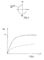
- Fig. 3 shows a diagram of the opening and closing times of the exhaust valves.
- the opening time of the exhaust valve 6 will therefore be relatively long.
- the crankshaft angle means the angle through which the crankshaft 3 has rotated since the piston 10 was located in the top dead-centre position. When the piston 10 is located in the top dead-centre position, the crankshaft angle is therefore zero.
- the electric motor/generator 17 can be controlled so that it increases the speed of the internal combustion engine 1 beyond the speed which the internal combustion engine 1 itself produces. This means that the electric motor/generator 17 drives the internal combustion engine 1. Energy is thus supplied to the internal combustion engine 1, which results in the heat flow to the catalytic converter 12 increasing, so that the catalytic converter 12 is heated more rapidly.
- Fig. 4 shows a diagram of the heating time of the catalytic converter 12 for a conventionally controlled internal combustion engine and an internal combustion engine 1 controlled according to the method according to the present invention.
- the solid curve in Fig. 3 relates to the heating time of the catalytic converter 12 for an internal combustion engine controlled according to the method according to the present invention, and the broken line relates to the heating time of the catalytic converter for a conventionally controlled internal combustion engine.
- the catalytic converter 12 of the internal combustion engine controlled according to the method according to the present invention will reach the working temperature To more rapidly than the catalytic converter of the engine controlled conventionally.
- the internal combustion engine 1 can be supercharged by means of an exhaust turbo or a mechanical compressor (not shown). In a supercharged internal combustion engine 1, energy is supplied from the compressor or the turbo, so that the combustion temperature after expansion in the cylinder increases further. The catalytic converter can thus also be heated more rapidly.
Landscapes
- Engineering & Computer Science (AREA)
- Chemical & Material Sciences (AREA)
- Combustion & Propulsion (AREA)
- Mechanical Engineering (AREA)
- General Engineering & Computer Science (AREA)
- Physics & Mathematics (AREA)
- Electromagnetism (AREA)
- Electrical Control Of Air Or Fuel Supplied To Internal-Combustion Engine (AREA)
- Exhaust Gas After Treatment (AREA)
- Combined Controls Of Internal Combustion Engines (AREA)
- Output Control And Ontrol Of Special Type Engine (AREA)
Abstract
Description
- The present invention relates to a method of reducing emissions in the exhaust gases of an internal combustion engine which comprises at least one cylinder to which an air/fuel mixture is supplied when a crankshaft of the internal combustion engine is to be made to rotate, at least one intake valve, at least one exhaust valve, and a piston reciprocating between a top dead-centre position and a bottom dead-centre position in the cylinder.
- In internal combustion engines, it is desirable to reduce substances or emissions present in the exhaust gases of the internal combustion engine in order thus to reduce pollution of the surrounding environment and to satisfy legal requirements for internal combustion engines. Emissions present in the exhaust gases include inter alia carbon monoxide CO, hydrocarbon compounds HC and nitrogen oxides NOx.
- In order to reduce these emissions in the exhaust gases, the internal combustion engine is provided with a catalytic converter which, by means of a chemical reaction, burns these undesirable emissions completely. The chemical reaction in the catalytic converter occurs only when the catalytic converter has reached a predetermined working temperature which is reached after a predetermined operating time of the internal combustion engine. When the engine is cold-started, there is therefore no reduction of the abovementioned undesirable emissions in the catalytic converter.
- There are known arrangements which heat the catalytic converter when the internal combustion engine is cold-started for the purpose of rapidly reaching a desirable working temperature of the catalytic converter so as thus to make it possible to reduce the undesirable emissions in the exhaust gases of the internal combustion engine at an early stage. In such a known arrangement, an electric heating element is arranged in the catalytic converter. This arrangement makes the catalytic converter complicated and expensive to produce.
- Internal combustion engines using starter generators are well known.
- In a four-stroke engine a usual opening time for the exhaust valve(s) is 45°-60° before BDC.
- Another problem which arises when internal combustion engines are cold-started is that a comparatively great amount of fuel in relation to the air supplied, that is to say a rich air/fuel mixture, has to be supplied to the internal combustion engine in order that the internal combustion engine will start and the internal combustion will be capable of working at an essentially constant speed during idle running. This rich air/fuel mixture is also supplied in order that the internal combustion engine will be ready to provide increased torque when the accelerator is operated. The operability of the internal combustion engine is thus ensured before the internal combustion engine has reached its operating temperature.
- The absence of emission control in the catalytic converter and the rich air/fuel mixture result in the content of carbon monoxide CO, hydrocarbon compounds HC and nitrogen oxides NOx emitted from the internal combustion engine being high when the internal combustion engine is cold-started.
- Attempts have previously been made tc reduce the quantity of fuel in relation to the air supplied, that is to say to run the internal combustion engine with a leaner air/fuel mixture when the internal combustion engine is cold-started. This has nevertheless led to the internal combustion engine working very unevenly when idling and also the operability of the internal combustion engine being poor. The reason why the speed varies during idle running is that the torque generated by the internal combustion engine is very sensitive to variations in the lambda value of the air/fuel mixture supplied to the cylinder space of the internal combustion engine when the air/fuel mixture is lean. The definition of the lambda value, or the excess air factor as it is also known, is the actual air quantity supplied divided by the air quantity theoretically necessary for complete combustion. If the lambda value is greater than 1, the air/fuel mixture is lean and, if the lambda value is smaller than one, the air/fuel mixture is rich.
- The fuel supplied from a fuel injection valve can be controlled accurately by means of the fuel injection system of the internal combustion engine in order thus to obtain an essentially constant lambda value for the air/fuel mixture supplied. When the internal combustion engine is cold, however, fuel will condense on the comparatively cold walls in the intake duct and in the cylinder. The fuel condensed on the walls will be vaporized during idle running and accompany the air/fuel mixture which is flowing in the intake duct and being supplied to the cylinder space. If the vaporization of the fuel condensed on the walls is uneven, on account of pressure variations, temperature gradients, or the flow rate of the air/fuel mixture in the intake duct, a variation of the lambda value of the air/fuel mixture supplied to the cylinder space will occur.
- As the torque generated by the internal combustion engine will vary during idle running when cold-started, the speed of the internal combustion engine will vary. In this connection, the speed of the internal combustion engine means the speed of rotation of the crankshaft of the internal combustion engine. When the speed varies, the pressure in the intake duct will also vary, which in turn leads to the vaporization of the condensed fuel varying, so that a variation of the lambda value of the air/fuel mixture supplied to the cylinder space occurs. The uneven speed of the internal combustion engine is thus intensified.
- The object of the present invention is to reduce carbon monoxide CO, hydrocarbon compounds HC and nitrogen oxides NOx in exhaust gases from an internal combustion engine when cold-started.
- Another object of the invention is to make it possible for an internal combustion engine to work with a lean air/fuel mixture.
- A further object of the invention is to reach the working temperature of the catalytic converter as rapidly as possible.
- This is achieved by a method of the type indicated in the introduction, which comprises the steps: an air/fuel mixture with a lambda value greater than 1 is supplied to the cylinder, an electric motor/generator connected to the crankshaft maintains an essentially constant predetermined speed of the crankshaft, and the exhaust valve is controlled so that it opens before the piston has passed the bottom dead-centre position.
- By supplying an air/fuel mixture greater than 1 to the cylinder, the abovementioned undesirable emissions in the exhaust gases emitted from the internal combustion engine are reduced. By means of the combined electric motor/generator, the internal combustion engine will work at an essentially constant speed during idle running. By controlling the exhaust valve so that it opens before the piston has passed the bottom dead-centre position, the expansion stroke of the piston in the cylinder is interrupted, and very hot gases flow out through the exhaust duct and on to the catalytic converter which will thus be heated rapidly.
- The invention is described in greater detail below by means of an exemplary embodiment shown in the appended drawings, in which
- Fig. 1 shows a section through an internal combustion engine,
- Fig. 2 shows a diagrammatic view of an internal combustion engine and an electric motor/generator for implementing the method according to the present invention,
- Fig. 3 shows a diagram of the opening and closing times of exhaust valves, and
- Fig. 4 shows a diagram of the heating time of the catalytic converter for a conventionally controlled internal combustion engine and an internal combustion engine controlled according to the method according to the present invention.
-
- Fig. 1 shows an
internal combustion engine 1 which comprises at least onecylinder 2 to which an air/fuel mixture is supplied when acrankshaft 3 of theinternal combustion engine 1 is to be made to rotate. At least one intake duct 4 is arranged so as to open andclose intake ducts 5 which are connected to thecylinder 2 and through which an air/fuel mixture is supplied when theengine 1 is working. At least one exhaust valve 6 is arranged so as to open andclose exhaust ducts 7 which are connected to thecylinder 2 and through which burnt fuel in the form of exhaust gases is removed when theengine 1 is working. Theinternal combustion engine 1 also comprisescontrol members 8 arranged so as to control the opening and closing of the intake and exhaust valves 4, 6. In the exemplary embodiment shown, thecontrol members 8 consist of camshafts which can be adjustable so that the opening and closing time of the intake and exhaust valves 4, 6 can be varied. This is brought about by, for example, aregulating arrangement 9 which is shown diagrammatically in Fig. 1 and in a manner known per se rotates the camshafts hydraulically.Other control members 8 are also possible, such as electromagnetically controlled valves. Apiston 10, which reciprocates between a top and a bottom dead-centre position in thecylinder 2, is mounted on thecrankshaft 3 by means of a connectingrod 11. During operation of theinternal combustion engine 1, exhaust gases flow from thecylinder 2 through theexhaust ducts 7 and on through acatalytic converter 12. Theinternal combustion engine 1 is preferably of the multi-cylinder four-stroke type. - Fig. 2 shows the
internal combustion engine 1 diagrammatically.Fuel injection nozzles 13 controlled by acontrol unit 14 are provided for theintake ducts 5. Thecontrol unit 14 is also connected to a number ofsensors 15 in theinternal combustion engine 1, which sense the speed, temperature etc. of theinternal combustion engine 1. It is also possible to arrangepressure sensors 16 in theintake ducts 5 in order to sense the pressure in theintake ducts 5. Thesepressure sensors 16 are connected to thecontrol unit 14. - An electric motor/
generator 17, which functions as an integrated starter motor and generator (ISG), is connected to thecrankshaft 3 of theinternal combustion engine 1. As an alternative to a direct connection of the electric motor/generator 17 to thecrankshaft 3, a belt, chain or gear transmission, for example, can be used to connect the electric motor/generator 17 to thecrankshaft 3. The electric motor/generator 17 is connected to abattery 18 via acontrol device 19. Thecontrol device 19 is connected to thecontrol unit 14 and obtains information from thecontrol unit 14 relating to how the electric motor/generator 17 is to be operated. - When the
internal combustion engine 1 is in operation, air enters anintake branch pipe 20 via anair intake pipe 21. From theintake branch pipe 20, the air flows on to theintake ducts 5 where the air is mixed with fuel which is injected into theintake ducts 5 by means of thefuel injection nozzles 13. The air/fuel mixture then flows into thecylinders 2 and is ignited by at least one spark plug (not shown) arranged in eachcylinder 2. Finally, the burnt air/fuel mixture in the form of exhaust gases flows out into the atmosphere through anexhaust system 22 connected to theinternal combustion engine 1. - As explained in the introduction of the description, the burnt air/fuel mixture contains emissions which are undesirable. These emissions include carbon monoxide CO, hydrocarbon compounds HC and nitrogen oxides NOx. The exhaust gases are therefore treated in a
catalytic converter 12 which is arranged in theexhaust system 22 and burns these emissions. However, thecatalytic converter 12 functions only when it has reached a given working temperature, which takes place after a given heating time after theinternal combustion engine 1 has been started. During cold-starting of theinternal combustion engine 1, there is therefore no conversion of the abovementioned emissions in thecatalytic converter 12. - The content of carbon monoxide CO, hydrocarbon compounds HC and nitrogen oxides NOx in the exhaust gases depends on inter alia the mixing ratio of the air/fuel mixture supplied to the
cylinders 2. This mixing ratio is usually indicated by a lambda value. The definition of the lambda value, or the excess air factor as it is also known, is the actual air quantity supplied divided by the air quantity theoretically necessary. If the lambda value is greater than 1, the air/fuel mixture is lean and, if the lambda value is smaller than one, the air/fuel mixture is rich. - By means of supplying an air/fuel mixture with a lambda value greater than 1, that is to say a lean air/fuel mixture, to the cylinders when the internal combustion engine is cold-started, the content of hydrocarbon compounds HC in the exhaust gases can be considerably reduced. If a lean air/fuel mixture is -supplied to the
internal combustion engine 1 when it is cold, that is to say when theinternal combustion engine 1 has not reached its working temperature, problems of uneven speed during idle running arise for the reason explained in the introduction of the description. - The electric motor/
generator 17 connected to thecrankshaft 3 maintains an essentially constant predetermined speed of thecrankshaft 3, which is brought about by virtue of the electric motor/generator 17 being controlled in order thus to control the speed of theinternal combustion engine 1 in such a manner that when the speed of theinternal combustion engine 1 exceeds a predetermined speed, the electric motor/generator 17 is controlled so that the speed of theinternal combustion engine 1 decreases. The electric motor/generator 17 then works as a generator and thus reduces the speed of theinternal combustion engine 1. When the speed of theinternal combustion engine 1 falls below a predetermined speed, the electric motor/generator 17 is controlled so that the speed of theinternal combustion engine 1 increases. The electric motor/generator 17 then works as an electric motor and thus increases the speed of theinternal combustion engine 1. Thesensor 15 senses the speed of theinternal combustion engine 1 by, for example, sensing the speed of thecrankshaft 3. Thesensor 15 sends signals to thecontrol unit 14 which processes these signals and then gives instructions to thecontrol device 19 which define how the electric motor/generator 17 is to work. - It is also possible to control the electric motor/
generator 17 so that the pressure in theintake ducts 5 is kept essentially constant. Apressure sensor 16 can be arranged in at least one of theintake ducts 5 in order to measure the pressure in theintake ducts 5. Thepressure sensor 16 is connected to thecontrol unit 14 of theinternal combustion engine 1, which sends signals to acontrol device 19 intended for the electric motor/generator 17. By maintaining an essentially constant pressure in theintake ducts 5 by means of the electric motor/generator 17, an essentially constant speed of theinternal combustion engine 1 can be obtained when theinternal combustion engine 1 is cold and is run with an air/fuel mixture which is lean. The pressure in theintake ducts 5 is controlled by means of the electric motor/generator 17 connected to thecrankshaft 3 in such a manner that, when the pressure in theintake ducts 5 exceeds a predetermined pressure, the electric motor/generator 17 drives thecrankshaft 3 in order thus to reduce the pressure in theintake ducts 5 and, when the pressure in theintake ducts 5 falls below a predetermined pressure, thecrankshaft 3 drives the electric motor/generator 17 in order thus to increase the pressure in theintake ducts 5. - When a cold
internal combustion engine 1 is started, thecatalytic converter 12 is also cold, as mentioned above. In order that thecatalytic converter 12 is to be capable of effectively reducing the undesirable emissions in the exhaust gases of theinternal combustion engine 1, thecatalytic converter 12 must reach a given working temperature. Ignition of the air/fuel mixture supplied to thecylinder 2 is carried out at a crankshaft angle of 10° before to 20° after the top dead-centre position, preferably at a crankshaft angle of 0° - 10° after the top dead-centre position. By controlling the exhaust valve 6, as the method according to the present invention proposes, so that it opens before thepiston 10 has passed the bottom dead-centre position during the expansion stroke, expansion is interrupted, and very hot exhaust gases will thus flow through theexhaust duct 7 and on to thecatalytic converter 12. Thecatalytic converter 12 will therefore be heated very rapidly to the desired working temperature by the hot exhaust gases. It has been found that if the exhaust valve 6 is controlled so that it opens at a crankshaft angle of 90° - 130° after the top dead-centre position, preferably at a crankshaft angle of 100° after the top dead-centre position, the working temperature of thecatalytic converter 12 will be reached very rapidly. Atemperature sensor 23 can be arranged so as to sense the temperature of thecatalytic converter 12 and send information about the temperature of thecatalytic converter 12 to thecontrol unit 14. - Fig. 3 shows a diagram of the opening and closing times of the exhaust valves. The opening time of the exhaust valve 6 will therefore be relatively long. In this connection, the crankshaft angle means the angle through which the
crankshaft 3 has rotated since thepiston 10 was located in the top dead-centre position. When thepiston 10 is located in the top dead-centre position, the crankshaft angle is therefore zero. - The electric motor/
generator 17 can be controlled so that it increases the speed of theinternal combustion engine 1 beyond the speed which theinternal combustion engine 1 itself produces. This means that the electric motor/generator 17 drives theinternal combustion engine 1. Energy is thus supplied to theinternal combustion engine 1, which results in the heat flow to thecatalytic converter 12 increasing, so that thecatalytic converter 12 is heated more rapidly. - Fig. 4 shows a diagram of the heating time of the
catalytic converter 12 for a conventionally controlled internal combustion engine and aninternal combustion engine 1 controlled according to the method according to the present invention. The solid curve in Fig. 3 relates to the heating time of thecatalytic converter 12 for an internal combustion engine controlled according to the method according to the present invention, and the broken line relates to the heating time of the catalytic converter for a conventionally controlled internal combustion engine. As can be seen from the diagram in Fig. 4, thecatalytic converter 12 of the internal combustion engine controlled according to the method according to the present invention will reach the working temperature To more rapidly than the catalytic converter of the engine controlled conventionally. - The
internal combustion engine 1 can be supercharged by means of an exhaust turbo or a mechanical compressor (not shown). In a superchargedinternal combustion engine 1, energy is supplied from the compressor or the turbo, so that the combustion temperature after expansion in the cylinder increases further. The catalytic converter can thus also be heated more rapidly.
Claims (10)
- Method of reducing emissions in the exhaust gases of an internal combustion engine (1) which comprises at least one cylinder (2) to which an air/fuel mixture is supplied when a crankshaft (3) of the internal combustion engine (1) is to be made to rotate, at least one intake valve (4), at least one exhaust valve (6), and a piston (10) reciprocating between a top dead-centre position and a bottom dead-centre position in the cylinder (2), wherein the method comprises the following steps: an air/fuel mixture with a lambda value greater than 1 is supplied to the cylinder (2), an electric motor/generator (17) connected to the crankshaft (3) maintains an essentially constant predetermined speed of the crankshaft (3), and the exhaust valve (6) is controlled so that it opens before the piston (10) has passed the bottom dead-centre position.
- Method according to Claim 1, characterized in that the exhaust valve (6) is controlled so that it opens at a crankshaft angle of 90° - 130° after the top dead-centre position, preferably at a crankshaft angle of 100° after the top dead-centre position.
- Method according to Claim 1 or 2, characterized in that the electric motor/generator (17) connected to the crankshaft is controlled so that, when the speed of the internal combustion engine (1) exceeds a predetermined speed, the electric motor/generator (17) works as a generator and thus reduces the speed of the internal combustion engine (1) and, when the speed of the internal combustion engine (1) falls below a predetermined speed, the electric motor/generator (17) works as an electric motor and thus increases the speed of the internal combustion engine (1).
- Method according to Claim 1 or 2, characterized in that the electric motor/generator (17) is controlled so that the electric motor/generator (17) drives the internal combustion engine (1) at a speed which is greater than the speed which the internal combustion engine (1) itself produces, which results in the heat flow to a catalytic converter (12) arranged in the internal combustion engine (1) increasing.
- Method according to Claim 1 or 2, characterized in that the electric motor/generator (17) connected to the crankshaft (3) is controlled so that, when the pressure in at least one intake duct (5) connected to the cylinder (2) exceeds a predetermined pressure, the electric motor/generator (17) drives the crankshaft (3) and, when the pressure in the intake duct (5) falls below a predetermined pressure, the crankshaft (3) drives the electric motor/generator (17).
- Method according to any one of the preceding claims, characterized in that the exhaust valve (6) is controlled so that the exhaust valve (6) closes when the piston (10) is located at the top dead-centre.
- Method according to any one of the preceding claims, characterized in that ignition of the air/fuel mixture supplied to the cylinder (2) is carried out at a crankshaft angle of 10° before to 30° after the top dead-centre position, preferably at a crankshaft angle of 0° - 10° after the top dead-centre position.
- Method according to any one of the preceding claims, characterized in that the lambda value of the air/fuel mixture supplied to the cylinder (2) lies essentially within the range 1.1 - 1.4 and preferably within the range 1.1 - 1.2.
- Method according to any one of the preceding claims, characterized in that the method is used essentially when cold-starting the- internal combustion engine (1).
- Method according to any one of the preceding claims, characterized in that adjustable control members (8) are arranged in the internal combustion engine (1) in order to control the opening and closing of the intake and exhaust valves (4, 6), so that the time of opening and closing of the intake and exhaust valves (4, 6) can be varied.
Applications Claiming Priority (3)
| Application Number | Priority Date | Filing Date | Title |
|---|---|---|---|
| SE9902218 | 1999-06-11 | ||
| SE9902218A SE521677C2 (en) | 1999-06-11 | 1999-06-11 | Method for reducing substances in exhaust gases from an internal combustion engine |
| PCT/SE2000/001192 WO2001002709A1 (en) | 1999-06-11 | 2000-06-08 | Method of reducing emissions in the exhaust gases of an internal combustion engine |
Publications (2)
| Publication Number | Publication Date |
|---|---|
| EP1185771A1 EP1185771A1 (en) | 2002-03-13 |
| EP1185771B1 true EP1185771B1 (en) | 2004-03-24 |
Family
ID=20416047
Family Applications (1)
| Application Number | Title | Priority Date | Filing Date |
|---|---|---|---|
| EP00941074A Expired - Lifetime EP1185771B1 (en) | 1999-06-11 | 2000-06-08 | Method of reducing emissions in the exhaust gases of an internal combustion engine |
Country Status (6)
| Country | Link |
|---|---|
| US (1) | US6609365B2 (en) |
| EP (1) | EP1185771B1 (en) |
| AU (1) | AU5583500A (en) |
| DE (1) | DE60009286T2 (en) |
| SE (1) | SE521677C2 (en) |
| WO (1) | WO2001002709A1 (en) |
Families Citing this family (2)
| Publication number | Priority date | Publication date | Assignee | Title |
|---|---|---|---|---|
| US7469667B2 (en) * | 2005-07-07 | 2008-12-30 | Ford Global Technologies, Llc | Method for controlling a variable event valvetrain |
| US7736608B2 (en) * | 2007-11-29 | 2010-06-15 | General Electric Company | Methods and systems for reducing the emissions from combustion gases |
Family Cites Families (16)
| Publication number | Priority date | Publication date | Assignee | Title |
|---|---|---|---|---|
| JPS56115540U (en) * | 1980-02-06 | 1981-09-04 | ||
| JPS58195043A (en) * | 1982-05-11 | 1983-11-14 | Nissan Motor Co Ltd | Speed controller for internal-combustion engine |
| US4619232A (en) * | 1985-05-06 | 1986-10-28 | Ford Motor Company | Interactive idle speed control with a direct fuel control |
| US5218945A (en) * | 1992-06-16 | 1993-06-15 | Gas Research Institute | Pro-active control system for a heat engine |
| US5517965A (en) * | 1993-09-20 | 1996-05-21 | Nissan Diesel Motor Co., Ltd. | Governor device for internal combustion engine |
| JP2587202B2 (en) * | 1994-08-22 | 1997-03-05 | 本田技研工業株式会社 | Power generation control device for hybrid vehicle |
| JP3562016B2 (en) * | 1994-09-06 | 2004-09-08 | マツダ株式会社 | Car lean burn engine |
| NL9500154A (en) * | 1995-01-27 | 1996-09-02 | Deltec Fuel Systems Bv | Method and device for measuring the NO emissions of an internal combustion engine. |
| US5630394A (en) * | 1996-03-04 | 1997-05-20 | Ford Motor Company | Idle speed control |
| JP2871615B2 (en) * | 1996-09-09 | 1999-03-17 | トヨタ自動車株式会社 | Exhaust gas purification device for internal combustion engine |
| US5738070A (en) * | 1996-12-11 | 1998-04-14 | Caterpillar Inc. | Method and apparatus for operation of a speed-governed lean burn engine to improve load response |
| DE19704153C2 (en) * | 1997-02-04 | 2000-10-19 | Isad Electronic Sys Gmbh & Co | Drive system, in particular for a motor vehicle and method for counteracting a change in the idle speed in a drive system |
| US6116213A (en) * | 1997-04-25 | 2000-09-12 | Honda Giken Kogyo Kabushiki Kaisha | Control system for controlling internal combustion engine |
| JP3506042B2 (en) * | 1999-04-27 | 2004-03-15 | トヨタ自動車株式会社 | Control device for internal combustion engine |
| JP3832701B2 (en) * | 1999-09-30 | 2006-10-11 | スズキ株式会社 | Control device for engine coupled motor |
| US6474291B2 (en) * | 2000-12-19 | 2002-11-05 | Visteon Global Technologies, Inc. | Clean shutdown for internal combustion engine with variable valve timing |
-
1999
- 1999-06-11 SE SE9902218A patent/SE521677C2/en not_active IP Right Cessation
-
2000
- 2000-06-08 DE DE60009286T patent/DE60009286T2/en not_active Expired - Lifetime
- 2000-06-08 WO PCT/SE2000/001192 patent/WO2001002709A1/en not_active Ceased
- 2000-06-08 AU AU55835/00A patent/AU5583500A/en not_active Abandoned
- 2000-06-08 EP EP00941074A patent/EP1185771B1/en not_active Expired - Lifetime
-
2001
- 2001-12-11 US US09/683,299 patent/US6609365B2/en not_active Expired - Lifetime
Also Published As
| Publication number | Publication date |
|---|---|
| AU5583500A (en) | 2001-01-22 |
| SE9902218D0 (en) | 1999-06-11 |
| SE9902218L (en) | 2000-12-12 |
| DE60009286T2 (en) | 2005-02-24 |
| EP1185771A1 (en) | 2002-03-13 |
| SE521677C2 (en) | 2003-11-25 |
| WO2001002709A1 (en) | 2001-01-11 |
| US6609365B2 (en) | 2003-08-26 |
| DE60009286D1 (en) | 2004-04-29 |
| US20020189239A1 (en) | 2002-12-19 |
Similar Documents
| Publication | Publication Date | Title |
|---|---|---|
| US6516774B2 (en) | Premixed charge compression ignition engine with variable speed SOC control and method of operation | |
| EP1224383B1 (en) | Method of reducing emissions in the exhaust gases of an internal combustion engine | |
| US4831993A (en) | Method of operating carburetted dual-fuel engines with diesel pilot oil injection | |
| WO2001046571A1 (en) | An auto-ignited homogenous charge four stroke engine | |
| US20040112307A1 (en) | Four stroke auto-ignition engine | |
| US20040011029A1 (en) | Method for heating a catalyst used in internal combustion engine with direct fuel injection | |
| US11215131B2 (en) | Internal combustion engine and method for controlling such an internal combustion engine | |
| US6837039B2 (en) | Device and method for controlling an internal combustion engine | |
| EP1185770B1 (en) | Method of reducing emissions in the exhaust gases of an internal combustion engine | |
| US6609365B2 (en) | Method of reduction emissions in the exhaust gases of an internal combustion engine | |
| JP3062576B2 (en) | Two-stroke internal combustion engine | |
| US6561170B2 (en) | Method of reducing emissions in the exhaust gases from an internal combustion engine | |
| EP1169559B1 (en) | Method of reduction of exhaust gas emissions from internal combustion engines | |
| EP3682099B1 (en) | Internal combustion engine and method for controlling such an internal combustion engine | |
| US6948309B2 (en) | Method of operating an internal combustion engine | |
| EP1566532B1 (en) | Method of reducing emissions in exhaust gases generated at a starting process of an internal combustion engine | |
| JP3312514B2 (en) | In-cylinder internal combustion engine | |
| JP2022076373A (en) | Six stroke internal combustion engine | |
| JPH03206315A (en) | Spark ignition piston type four-cycle internal combustion engine device | |
| GB2393758A (en) | An auto-ignited homogeneous charge four stroke engine |
Legal Events
| Date | Code | Title | Description |
|---|---|---|---|
| PUAI | Public reference made under article 153(3) epc to a published international application that has entered the european phase |
Free format text: ORIGINAL CODE: 0009012 |
|
| 17P | Request for examination filed |
Effective date: 20011211 |
|
| AK | Designated contracting states |
Kind code of ref document: A1 Designated state(s): AT BE CH CY DE DK ES FI FR GB GR IE IT LI LU MC NL PT |
|
| AX | Request for extension of the european patent |
Free format text: AL;LT;LV;MK;RO;SI |
|
| GRAP | Despatch of communication of intention to grant a patent |
Free format text: ORIGINAL CODE: EPIDOSNIGR1 |
|
| GRAS | Grant fee paid |
Free format text: ORIGINAL CODE: EPIDOSNIGR3 |
|
| GRAA | (expected) grant |
Free format text: ORIGINAL CODE: 0009210 |
|
| RIN1 | Information on inventor provided before grant (corrected) |
Inventor name: ALMKVIST, GOERAN Inventor name: THORN, KARIN |
|
| AK | Designated contracting states |
Kind code of ref document: B1 Designated state(s): DE FR GB |
|
| REG | Reference to a national code |
Ref country code: GB Ref legal event code: FG4D |
|
| REG | Reference to a national code |
Ref country code: IE Ref legal event code: FG4D |
|
| REF | Corresponds to: |
Ref document number: 60009286 Country of ref document: DE Date of ref document: 20040429 Kind code of ref document: P |
|
| PG25 | Lapsed in a contracting state [announced via postgrant information from national office to epo] |
Ref country code: GB Free format text: LAPSE BECAUSE OF NON-PAYMENT OF DUE FEES Effective date: 20040624 |
|
| LTIE | Lt: invalidation of european patent or patent extension |
Effective date: 20040324 |
|
| ET | Fr: translation filed | ||
| PLBE | No opposition filed within time limit |
Free format text: ORIGINAL CODE: 0009261 |
|
| STAA | Information on the status of an ep patent application or granted ep patent |
Free format text: STATUS: NO OPPOSITION FILED WITHIN TIME LIMIT |
|
| GBPC | Gb: european patent ceased through non-payment of renewal fee |
Effective date: 20040624 |
|
| REG | Reference to a national code |
Ref country code: IE Ref legal event code: MM4A |
|
| 26N | No opposition filed |
Effective date: 20041228 |
|
| PG25 | Lapsed in a contracting state [announced via postgrant information from national office to epo] |
Ref country code: FR Free format text: LAPSE BECAUSE OF NON-PAYMENT OF DUE FEES Effective date: 20040630 |
|
| REG | Reference to a national code |
Ref country code: FR Ref legal event code: ST Effective date: 20111007 |
|
| PGFP | Annual fee paid to national office [announced via postgrant information from national office to epo] |
Ref country code: DE Payment date: 20140618 Year of fee payment: 15 |
|
| REG | Reference to a national code |
Ref country code: DE Ref legal event code: R119 Ref document number: 60009286 Country of ref document: DE |
|
| PG25 | Lapsed in a contracting state [announced via postgrant information from national office to epo] |
Ref country code: DE Free format text: LAPSE BECAUSE OF NON-PAYMENT OF DUE FEES Effective date: 20160101 |