EP1185129A2 - Optical distribution network system that performs system switching only when total operation condition is improved - Google Patents
Optical distribution network system that performs system switching only when total operation condition is improved Download PDFInfo
- Publication number
- EP1185129A2 EP1185129A2 EP01120078A EP01120078A EP1185129A2 EP 1185129 A2 EP1185129 A2 EP 1185129A2 EP 01120078 A EP01120078 A EP 01120078A EP 01120078 A EP01120078 A EP 01120078A EP 1185129 A2 EP1185129 A2 EP 1185129A2
- Authority
- EP
- European Patent Office
- Prior art keywords
- optical
- line termination
- optical network
- switching
- working side
- Prior art date
- Legal status (The legal status is an assumption and is not a legal conclusion. Google has not performed a legal analysis and makes no representation as to the accuracy of the status listed.)
- Withdrawn
Links
Images












Classifications
-
- H—ELECTRICITY
- H04—ELECTRIC COMMUNICATION TECHNIQUE
- H04Q—SELECTING
- H04Q11/00—Selecting arrangements for multiplex systems
- H04Q11/0001—Selecting arrangements for multiplex systems using optical switching
- H04Q11/0062—Network aspects
-
- H—ELECTRICITY
- H04—ELECTRIC COMMUNICATION TECHNIQUE
- H04L—TRANSMISSION OF DIGITAL INFORMATION, e.g. TELEGRAPHIC COMMUNICATION
- H04L12/00—Data switching networks
- H04L12/54—Store-and-forward switching systems
- H04L12/56—Packet switching systems
- H04L12/5601—Transfer mode dependent, e.g. ATM
- H04L2012/5625—Operations, administration and maintenance [OAM]
- H04L2012/5627—Fault tolerance and recovery
-
- H—ELECTRICITY
- H04—ELECTRIC COMMUNICATION TECHNIQUE
- H04Q—SELECTING
- H04Q11/00—Selecting arrangements for multiplex systems
- H04Q11/0001—Selecting arrangements for multiplex systems using optical switching
- H04Q11/0062—Network aspects
- H04Q11/0067—Provisions for optical access or distribution networks, e.g. Gigabit Ethernet Passive Optical Network (GE-PON), ATM-based Passive Optical Network (A-PON), PON-Ring
-
- H—ELECTRICITY
- H04—ELECTRIC COMMUNICATION TECHNIQUE
- H04Q—SELECTING
- H04Q11/00—Selecting arrangements for multiplex systems
- H04Q11/0001—Selecting arrangements for multiplex systems using optical switching
- H04Q11/0062—Network aspects
- H04Q2011/0079—Operation or maintenance aspects
- H04Q2011/0081—Fault tolerance; Redundancy; Recovery; Reconfigurability
Definitions
- the present invention relates to an optical distribution network system that controls a duplex passive optical network (PON) section.
- PON passive optical network
- a conventional optical distribution network system which comprises an optical line termination and a plurality of optical network units connected to the optical line termination through optical fibers.
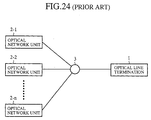
- Fig. 24 is a block diagram showing a schematic diagram of such a system, that is, a conventional optical distribution network system defined in ITU-T (International Telecommunication Union-Telecommunication) Recommendation G.983.1.
- ITU-T International Telecommunication Union-Telecommunication
- a downstream optical signal from an optical line termination 1 is split and broadcast to optical network units 2-1 - 2-n via an optical splitter 3.
- upstream signals from the optical network units 2-1 - 2-n are multiplexed by the optical splitter 3 to be transmitted to the optical line termination 1.
- access control delay control
- the delay control is also described in the ITU-T Recommendation G.983.1.
- ITU-T Recommendations I.630 and G.783 define a redundant optical network system with a complete duplex configuration between a location EAST and a location WEST as shown in Fig. 25.
- the reference numeral 23 designates a 2-1 selector for selecting and outputting the traffic received by the working side east side line termination 13 or by the standby side east side line termination 14 under the control of the selection controller 25; 24 designates a routing section for supplying the traffic to at least one of the working side east side line termination 13 and the standby side east side line termination 14 under the control of the selection controller 25; and 25 designates the selection controller for controlling the 2-1 selector 23 and routing section 24 in response to the selection signal.
- the reference numeral 26 designates a working side west side line termination
- 27 designates a standby side west side line termination
- reference numerals 28 and 29 each designate a receiving section for receiving the traffic and a selection signal transmitted from the location EAST 11
- 30 and 31 each designate a selection signal demultiplexer for extracting the selection signal received by the receiving section 28 or 29, and supplies the selection signal to a selection controller 38
- 32 and 33 each designate a selection signal multiplexer for supplying a selection signal output from the selection controller 38 to the transmitting section 34 or 35
- 34 and 35 each designate the transmitting section for transmitting the traffic and selection signal to the location EAST 11.
- the reference numeral 36 designates a 2-1 selector for selecting and outputting the traffic received by the working side west side line termination 26 or by the standby side west side line termination 27 under the control of the selection controller 38; 37 designates a routing section for supplying the traffic to at least one of the working side west side line termination 26 and the standby side west side line termination 27 under the control of the selection controller 38; and 38 designates the selection controller for controlling the 2-1 selector 36 and routing section 37 in response to the selection signal.
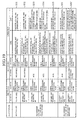
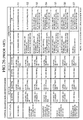
- Fig. 26 is a table describing a control example when detecting an equipment failure at the location EAST 11.
- the protocol of Fig. 26 is based on the ITU-T Recommendation I.630.
- the operation will be described taking an example where the location EAST 11 has a failure. It is assumed here that when the location EAST 11 operates normally, the 2-1 selector 23 and routing section 24 select the working side east side line termination 13, and the 2-1 selector 36 and routing section 37 select the working side west side line termination 26. Accordingly, the traffic is transmitted and received through the working side.
- the selection controller 25 of the location EAST 11 supplies the working side and standby side selection signal multiplexers 19 and 20 with a selection signal consisting of a K1 byte indicating "No switching request" and a K2 byte indicating "Selecting working side".
- the selection signal is transmitted to the location WEST 12 by the transmitting sections 21 and 22 in the location EAST 11, and is received by the receiving sections 28 and 29 in the location WEST 12. Then, the selection signal demultiplexers 30 and 31 supply the selection signal to the selection controller 38.
- the selection controller 38 in the location WEST 12 controls the 2-1 selector 36 and routing section 37 in response to the selection signal.
- the selection controller 38 Since the K1 byte indicates "No switching request", the selection controller 38 maintains the selection state of the 2-1 selector 36 and routing section 37, that is, maintains the selection of the working side.
- the location WEST 12 also transmits the selection signal consisting of the K1 byte and K2 byte to the location EAST 11. However, since it is assumed that the location WEST 12 always operates normally in the example, it continues to transmit the K1 byte indicating "No switching request".
- the selection controller 25 of the location EAST 11 outputs a command to switch the 2-1 selector 23 and routing section 24 to the standby side.
- the selection controller 25 of the location EAST 11 supplies the working side and standby side selection signal multiplexers 19 and 20 with the selection signal consisting of the K1 byte indicating "Switching request due to SF (signal fail) on a working side” and the K2 byte indicating "Selecting standby side".
- the selection signal is transmitted to the location WEST 12 by the transmitting sections 21 and 22 in the location EAST 11, and is received by the receiving sections 28 and 29 in the location WEST 12. Then the selection signal demultiplexers 30 and 31 supply the selection signal to the selection controller 38.
- the selection controller 38 in the location WEST 12 controls the 2-1 selector 36 and routing section 37 in response to the selection signal.
- the selection controller 38 Since the K1 byte indicates "Switching request due to SF (signal fail) on a working side" and the K2 byte indicates "Selecting standby side", the selection controller 38 outputs a command to switch the 2-1 selector 36 and routing section 37 to the standby side. Subsequently, the traffic is transmitted and received via the standby side.
- the location WEST 12 which cannot detect the equipment failure of the location EAST 11 at stage S2, transmits the K2 byte indicating "Selecting working side" at the stage S2. However, at stage S3, since it detects the equipment failure of the location EAST 11, it transmits the K2 byte indicating "Selecting standby side".
- the selection controller 25 of the location EAST 11 maintains the selection state of the 2-1 selector 23 and routing section 24, that is, the selection of the standby side.
- the selection controller 25 of the location EAST 11 supplies the working side and standby side selection signal multiplexers 19 and 20 with the selection signal consisting of the K1 byte indicating "Do not revert to working side” and the K2 byte indicating "Selecting standby side".
- the selection signal is transmitted to the location WEST 12 by the transmitting sections 21 and 22 in the location EAST 11, and is received by the receiving sections 28 and 29 in the location WEST 12. Then, the selection signal demultiplexers 30 and 31 supply the selection signal to the selection controller 38.
- the selection controller 38 in the location WEST 12 controls the 2-1 selector 36 and routing section 37 in response to the selection signal.
- the selection controller 38 maintains the selection state of the 2-1 selector 36 and routing section 37, that is, the selection of the standby side.
- the selection controller 25 of the location EAST 11 outputs a command to switch the 2-1 selector 23 and routing section 24 to the working side.
- the selection controller 25 of the location EAST 11 supplies the working side and standby side selection signal multiplexers 19 and 20 with the selection signal consisting of K1 byte indicating "Switching request due to SD (signal degrade) of standby side” and the K2 byte indicating "Selecting working side”.
- the selection signal is transmitted to the location WEST 12 by the transmitting sections 21 and 22 in the location EAST 11, and is received by the receiving sections 28 and 29 in the location WEST 12. Then, the selection signal demultiplexers 30 and 31 supply the selection signal to the selection controller 38.
- the selection controller 38 in the location WEST 12 controls the 2-1 selector 36 and routing section 37 in response to the selection signal.
- the selection controller 38 Since the K1 byte indicates "Switching request due to SD (signal degrade) of standby side" and the K2 byte indicates "Selecting working side", the selection controller 38 outputs a command to switch the 2-1 selector 36 and routing section 37 to the working side. Subsequently, the traffic is transmitted and received via the working side.
- the location WEST 12 which cannot detect the signal degrade in the location EAST 11 at stage S5, transmits the K2 byte indicating "Selecting standby side" at stage S5. However, at stage S6, since it detects the signal degrade of the location EAST 11, it transmits the K2 byte indicating "Selecting working side".
- the selection controller 25 of the location EAST 11 maintains the selection state of the 2-1 selector 23 and routing section 24, that is, the selection of the working side.
- the selection controller 25 of the location EAST 11 supplies the working side and standby side selection signal multiplexers 19 and 20 with the selection signal consisting of the K1 byte indicating "No switching request" and the K2 byte indicating "Selecting working side".
- the selection signal is transmitted to the location WEST 12 by the transmitting sections 21 and 22 in the location EAST 11, and is received by the receiving sections 28 and 29 in the location WEST 12. Then, the selection signal demultiplexers 30 and 31 supply the selection signal to the selection controller 38.
- the selection controller 38 in the location WEST 12 controls the 2-1 selector 36 and routing section 37 in response to the selection signal.
- the selection controller 38 maintains the selection state of the 2-1 selector 36 and routing section 37, that is, the selection of the working side.
- the location EAST 11 carries out the switching control to the standby side by itself if it detects the equipment failure of the working side. Accordingly, when the network system has a tree configuration, in which a plurality of locations EAST 11 are connected to the location WEST 12, the following problem can arise (as for the tree configuration, see Fig. 24, in which the optical network units 2-1 - 2-n each correspond to the location EAST 11, and the optical line termination 1 correspond to the location WEST 12).
- the working side of the optical network unit 2-1 has a failure, and the standby side thereof is normal, it carries out the switching from the working side to the standby side, even if the standby sides of the other optical network units 2-2 - 2-n have a failure, thereby worsening the total system operation.
- the present invention is implemented to solve the foregoing problem. It is therefore an object of the present invention to provide an optical distribution network system capable of carrying out the switching control of the system only when the total system operation is improved.
- an optical distribution network system comprising: an optical line termination; a plurality of optical network units, each of which is connected to the optical line termination through at least one of a first optical network and a second optical network; monitoring means installed in the optical line termination for detecting a system switching request from each of the plurality of optical network units; and control means installed in the optical line termination for controlling system switching between a working side and a standby side of each of the plurality of optical network units.
- control means may employ a tree switching method that carries out the system switching between the working side and the standby side of all of the plurality of optical network units at once, when carrying out the system switching of any one of the plurality of optical network units.
- the control means may employ a branch switching method that carries out the system switching between the working side and the standby side of only one of the plurality of optical network units, when carrying out the system switching.
- the control means may make a decision as to whether to carry out the system switching considering failure conditions of all of the plurality of optical network units.
- control means may perform switching control only when a number of failed units on the standby side is less than a number of failed units on the working side.
- control means may perform switching control only when a number of failed units on the working side is less than a number of failed units on the standby side.
- Each of the plurality of optical network units may further comprise switching means for carrying out the system switching between the working side and the standby side when it receives a system switching command from the optical line termination.
- the control means may carry out the system switching only when a system switching request from one of the plurality of optical network units continues for more than a predetermined time period.
- the control means may carry out its switching control in a duplex optical distribution network system on a passive optical network system.
- the optical line termination may further comprise output selecting means for outputting one of upstream messages that are copied via the working side and the standby side by at least one of the plurality of optical network units, and at least one of the plurality of optical network units may further comprise output selecting means for outputting one of downstream messages that are copied via the working side and the standby side by the optical line termination.
- At least one of the plurality of optical network units may comprise transmission stop means for halting transmission of one of the upstream messages to be copied to the working side and standby side of the optical line termination.
- At least one of the plurality of optical network units may comprise a gate for preventing one of the messages to be copied from being copied by suppressing it.
- the optical line termination may comprise a gate for preventing one of the messages to be copied from being copied by suppressing it.
- the control means may prevent the message of the selected side from being output until a predetermined time has elapsed after the system switching.
- Fig. 1 is a block diagram showing an entire configuration of an embodiment 1 of the optical distribution network system in accordance with the present invention.
- the reference numeral 51 designates an optical line termination (OLT); reference numerals 52-1 - 52-n each designate an optical network unit (ONU); the reference numeral 53 designate an ODN (Optical Distribution Network) consisting of optical couplers and the like; 61 designates a working side line termination section of the OLT; 62 designates a standby side line termination section of the OLT; 63 designates a working side line termination section of the ONU and 64 designates a standby side line termination section of the ONU.
- OLT optical line termination
- ONU optical network unit
- ODN Optical Distribution Network
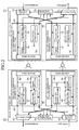
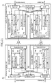
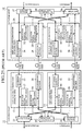
- Fig. 2 is a block diagram showing a detailed configuration of the embodiment 1 of the optical distribution network system in accordance with the present invention.
- the reference numeral 52 designates one of the optical network units 52-1 - 52-n;
- 71 designates a 2-1 selector for selecting and outputting either the traffic received by the working side line termination section of the OLT 61 or the traffic received by the standby side line termination section of the OLT 62 under the control of a selection controller 73;
- 72 designates a routing section for supplying the traffic to at least one of the working side line termination section of the OLT 61 and the standby side line termination section of the OLT 62 under the control of the selection controller 73;
- 73 designates the selection controller for controlling the 2-1 selector 71 and routing section 72 in response to the K1/K2 byte included in a PST (PON Section Trace) message, one of the PLOAM (Physical Layer Operations and Maintenance) cells.
- PST PON Section Trace
- PLOAM Physical Layer Operations
- Reference numerals 74 and 75 each designate a PLOAM cell multiplexer for supplying a PST message, one of PLOAM cells, which is output from the selection controller 73, to a transmitting/receiving (TX/RX) section 78 or 79; 76 and 77 each designate a grant generator for generating a PLOAM grant for carrying out delay control, and for supplying the PLOAM grant to the TX/RX section 78 or 79; 78 and 79 each designate the TX/RX section for transmitting the traffic, PLOAM cells and PLOAM grants to the optical network unit 52, and for receiving the traffic and PLOAM cells from the optical network unit 52; and 80 and 81 each designate a PLOAM cell demultiplexer for extracting the PLOAM cells received by the TX/RX section 78 or 79, and for supplying the PST message, one of PLOAM cells, to the selection controller 73.
- TX/RX transmitting/receiving
- the reference numeral 82 designates a 2-1 selector for selecting and outputting the traffic received by the working side line termination section of the ONU 63 or by the standby side line termination section of the ONU 64 under the control of a selection controller 84; 83 designates a routing section for supplying the traffic to at least one of the working side line termination section of the ONU 63 and standby side line termination section of the ONU 64 under the control of the selection controller 84; and 84 designates the selection controller for controlling the 2-1 selector 82 and routing section 83 in response to a PST message, one of PLOAM cells.
- Reference numeral 85 and 86 each designate a grand detector for detecting a PLOAM grant received by a TX/RX section 89 or 90; 87 and 88 each designate a PLOAM cell multiplexer for supplying the TX/RX section 89 or 90 with a PLOAM cell including the PST message output from the selection controller 84 at the timing indicated by the PLOAM grant detected by the grand detector 85 or 86; 89 and 90 each designate the TX/RX section for transmitting the traffic and PLOAM cells to the optical line termination 51, and for receiving the traffic, PLOAM cells and PLOAM grants from the optical line termination 51; and 91 and 92 each designate a PLOAM cell demultiplexer for extracting the traffic received by the TX/RX section 89 or 90, and for supplying the PST message, one of PLOAM cells, to the selection controller 84.
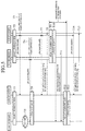
- the operation will be described taking an example where a failure happens in the optical network unit 52. It is assumed that when the optical network unit 52 is normal, the 2-1 selector 82 and routing section 83 select the traffic from the working side line termination section of the ONU 63, and the 2-1 selector 71 and routing section 72 select the traffic from the working side line termination section of the OLT 61. Accordingly, the traffic is transmitted and received through the working side.
- the selection controller 84 of the optical network unit 52 supplies the working side and standby side PLOAM cell multiplexers 87 and 88 with a PST message consisting of a K1 byte indicating "No switching request" and a K2 byte indicating "Selecting working side".
- the PLOAM cell including the PST message is transmitted to the optical line termination 51 by the TX/RX sections 89 and 90 of the optical network unit 52, and is received by the TX/RX sections 78 and 79 of the optical line termination 51. Then, the PLOAM cell demultiplexer 80 and 81 supply the PST message contained in the PLOAM cell to the selection controller 73.
- the selection controller 73 of the optical line termination 51 controls the 2-1 selector 71 and routing section 72 in response to the PST message.
- the selection controller 73 maintains the selection state of the 2-1 selector 71 and routing section 72, that is, maintains the selection of the working side.
- optical line termination 51 also transmits a PST message consisting of the K1 byte and K2 byte to the optical network unit 52 just as the optical network unit 52, since the optical line termination 51 is assumed to be always normal, it continues to transmit the K1 byte indicating "No switching request".
- the selection controller 84 of the optical network unit 52 supplies the working side and standby side PLOAM cell multiplexers 87 and 88 with the PST message consisting of the K1 byte indicating "Switching request due to SF (signal fail) on a working side" and the K2 byte indicating "Selecting working side".
- the PLOAM cell including the PST message is transmitted to the optical line termination 51 by the TX/RX sections 89 and 90 of the optical network unit 52, and is received by the TX/RX sections 78 and 79 of the optical line termination 51. Then, the PLOAM cell demultiplexers 80 and 81 supply the PST message contained in the PLOAM cell to the selection controller 73.
- the selection controller 73 of the optical line termination 51 controls the 2-1 selector 71 and routing section 72 in response to the PST message.
- the selection controller 73 outputs a command to switch the 2-1 selector 71 and routing section 72 to the standby side.
- the optical line termination 51 transmits the K2 byte indicating "Selecting working side” at stage S12 because it cannot detect the equipment failure of the optical network unit 52. In contrast, it transmits the K2 byte indicating "Selecting standby side” at stage S13 because it detects the equipment failure of the optical network unit 52.
- the optical line termination 51 decides whether to carry out the system switching control considering the fail state of all the optical network units 52-1 - 52-n (decides whether to update the K2 byte or not).
- the system switching control is allowed only when the number of failed units on the standby side is less than the number of failed units on the working side among all the optical network units 52-1 - 52-n.
- the branch switching method that can carry out the switching for each optical network unit independently, and hence can connect each optical network unit to a desired side, only the system of the failed optical network unit 52 is switched, with leaving the systems of the other optical network units as they are.
- the selection controller 73 of the optical line termination 51 supplies the working side and standby side PLOAM cell multiplexers 74 and 75 with the PST message consisting of the K1 byte indicating "No switching request" and the K2 byte indicating "Selecting standby side” at stage S13.
- the PLOAM cell including the PST message is transmitted to the optical network unit 52 by the TX/RX sections 78 and 79 of the optical line termination 51, and is received by the TX/RX sections 89 and 90 of the optical network unit 52. Then, the PLOAM cell demultiplexers 91 and 92 supply the PST message contained in the PLOAM cell to the selection controller 84.
- the selection controller 84 of the optical network unit 52 controls the 2-1 selector 82 and routing section 83 in response to the PST message at stage S14.
- the selection controller 84 outputs a command to switch the 2-1 selector 82 and routing section 83 to the standby side. Subsequently, the traffic is transmitted and received via the standby side.
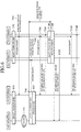
- the selection controller 84 of the optical network unit 52 supplies the working side and standby side PLOAM cell multiplexers 87 and 88 with the PST message consisting of the K1 byte indicating "Do not revert to working side” or "No switching request" and the K2 byte indicating "Selecting standby side".
- the PLOAM cell including the PST message is transmitted to the optical line termination 51 by the TX/RX sections 89 and 90 of the optical network unit 52, and is received by the TX/RX sections 78 and 79 of the optical line termination 51. Then, the PLOAM cell demultiplexers 80 and 81 supply the PST message contained in the PLOAM cell to the selection controller 73.
- the selection controller 73 of the optical line termination 51 controls the 2-1 selector 71 and routing section 72 in response to the PST message.
- the optical line termination 51 maintains the selection state of the 2-1 selector 71 and routing section 72, that is, maintains the selection of the standby side.
- the selection controller 84 of the optical network unit 52 supplies the working side and standby side PLOAM cell multiplexers 87 and 88 with the PST message consisting of the K1 byte indicating "Switching request due to SD (signal degrade) on a standby side" and the K2 byte indicating "Selecting standby side".
- the PLOAM cell including the PST message is transmitted to the optical line termination 51 by the TX/RX sections 89 and 90 of the optical network unit 52, and is received by the TX/RX sections 78 and 79 of the optical line termination 51. Then, the PLOAM cell demultiplexers 80 and 81 supply the PST message contained in the PLOAM cell to the selection controller 73.
- the selection controller 73 of the optical line termination 51 controls the 2-1 selector 71 and routing section 72 in response to the PST message.
- the selection controller 73 outputs a command to switch the 2-1 selector 71 and routing section 72 to the working side.
- the optical line termination 51 since the optical line termination 51 cannot detect the signal degrade of the optical network unit 52 at stage S16, it transmits the K2 byte indicating "Selecting standby side" at this stage. In contrast, at stage S17, it transmits the K2 byte indicating "Selecting working side” because it detects the signal degrade of the optical network unit 52 at this stage.
- the optical line termination 51 decides whether to carry out the system switching control considering the fail state of all the optical network units 52-1 - 52-n (decides whether to update the K2 byte or not).
- the system switching control is allowed only when the number of failed units on the working side is less than the number of failed units on the standby side among all the optical network units 52-1 - 52-n.
- the selection controller 73 of the optical line termination 51 supplies the working side and standby side PLOAM cell multiplexers 74 and 75 with the PST message consisting of the K1 byte indicating "No switching request" and the K2 byte indicating "Selecting working side” as described above.
- the PLOAM cell including the PST message is transmitted to the optical network unit 52 by the TX/RX sections 78 and 79 of the optical line termination 51, and is received by the TX/RX sections 89 and 90 of the optical network unit 52. Then, the PLOAM cell demultiplexers 91 and 92 supply the PST message contained in the PLOAM cell to the selection controller 84.
- the selection controller 84 of the optical network unit 52 controls the 2-1 selector 82 and routing section 83 in response to the PST message at stage S18.
- the selection controller 84 outputs a command to switch the 2-1 selector 82 and routing section 83 to the working side. Subsequently, the traffic is transmitted and received via the working side.
- the selection controller 84 of the optical network unit 52 supplies the working side and standby side PLOAM cell multiplexers 87 and 88 with the PST message consisting of the K1 byte indicating "No switching request" and the K2 byte indicating "Selecting working side".
- the PLOAM cell including the PST message is transmitted to the optical line termination 51 by the TX/RX sections 89 and 90 of the optical network unit 52, and is received by the TX/RX sections 78 and 79 of the optical line termination 51. Then, the PLOAM cell demultiplexers 80 and 81 supply the PST message contained in the PLOAM cell to the selection controller 73.
- the selection controller 73 of the optical line termination 51 controls the 2-1 selector 71 and routing section 72 in response to the PST message.
- the optical line termination 51 maintains the selection state of the 2-1 selector 71 and routing section 72, that is, maintains the selection of the working side.
- the present embodiment 1 is configured such that the optical line termination monitors the system switching request by the optical network unit, and controls the switching between the working side and the standby side system.
- the present embodiment 1 offers an advantage of being able to carry out the switching control of the system only when the total system operation is improved.
- Fig. 5 is a sequence diagram illustrating a system switching due to an equipment failure in the present embodiment 1; and Fig. 6 is a sequence diagram illustrating a system switching due to an equipment failure in a conventional example.
- the optical line termination 51 carries out the system switching first (see, T9), followed by the system switching by the optical network unit 52 (see, T12).
- T9 the system switching by the optical network unit 52
- T12 the system switching by the optical network unit 52
- the optical network unit carries out the system switching first (see, T96), and then transmits the PLOAM cell consisting of the K1 byte and K2 byte to the optical line termination (corresponding to the location WEST 12) at the timing indicated by the PLOAM grant, followed by the system switching by the optical line termination in response to the K1 byte and K2 byte (see, T100).
- T96 system switching first
- T100 the timing indicated by the PLOAM grant
- the conventional example takes extra time by an amount of transmitting the PLOAM cell to the optical line termination at the timing indicated by the PLOAM grant.
- the foregoing embodiment 1 handles the non-revertive mode that prevents the reversion back to the working side even when the equipment failure of the working side TX/RX section 89 is restored, it can also handle the revertive mode that requests the reversion back to the working side.
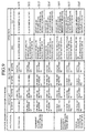
- Fig. 7 is a table showing a control example carried out when an equipment failure is detected in the optical network unit 52 (revertive mode).
- stages S11 - S14 because it is the same as that of Fig. 3.
- the selection controller 84 of the optical network unit 52 supplies the working side and standby side PLOAM cell multiplexers 87 and 88 with the PST message consisting of the K1 byte indicating "Request to revert back to working side” or "No switching request” and the K2 byte indicating "Selecting standby side".
- the PLOAM cell including the PST message is transmitted to the optical line termination 51 by the TX/RX sections 89 and 90 of the optical network unit 52, and is received by the TX/RX sections 78 and 79 of the optical line termination 51. Then the PLOAM cell demultiplexers 80 and 81 supply the PST message contained in the PLOAM cell to the selection controller 73.
- the selection controller 73 of the optical line termination 51 controls the 2-1 selector 71 and routing section 72 in response to the PST message.
- the selection controller 73 starts a restore timer not shown, and maintains the selection state of the 2-1 selector 71 and routing section 72, that is, maintains the selection of the standby side at this stage.
- the stage S22 is entered, in which the selection controller 73 of the optical line termination 51 outputs a command to revert the 2-1 selector 71 and routing section 72 back to the working side.
- the selection controller 73 of the optical line termination 51 supplies the working side and standby side PLOAM cell multiplexers 74 and 75 with the PST message consisting of the K1 byte indicating "No switching request" and the K2 byte indicating "Selecting working side".
- the PLOAM cell including the PST message is transmitted to the optical network unit 52 by the TX/RX sections 78 and 79 of the optical line termination 51, and is received by the TX/RX sections 89 and 90 of the optical network unit 52. Then, the PLOAM cell demultiplexers 91 and 92 supply the PST message contained in the PLOAM cell to the selection controller 84.
- the selection controller 84 of the optical network unit 52 controls the 2-1 selector 82 and routing section 83 in response to the PST message.
- the selection controller 84 outputs a command to switch the 2-1 selector 82 and routing section 83 to the working side. Subsequently, the traffic is transmitted and received via the working side.
- the selection controller 84 of the optical network unit 52 transmits the PST message consisting of the K1 byte indicating "No switching request" and the K2 byte indicating "Selecting working side” to the optical line termination 51 at stage S23.
- Fig. 8 is a sequence diagram illustrating a system switching at an equipment failure in the present embodiment 2. As clearly seen from this figure, the duration of a mismatch between selected systems becomes equal to that of the foregoing embodiment 1.
- the optical line termination 51 always transmits the K1 byte indicating "No switching request", and the optical network unit 52 carries out the system switching in response to the K2 byte in the foregoing embodiments 1 and 2, this is not essential.
- the optical line termination 51 can updates the K1 byte as needed, and the optical network unit 52 can carry out the system switching in response to the K1 and K2 bytes.
- Figs. 9 and 10 are tables showing a control example carried out when an equipment failure is detected in the optical network unit 52 (non-revertive mode), which correspond to Figs. 3 and 4 of the foregoing embodiment 1.
- the optical line termination 51 of the present embodiment 3 transmits the K1 byte indicating "Switching request due to working side SF" at stage S13' instead of the K1 byte indicating "No switching request" at stage 13 of Fig. 3, for example.
- Figs. 11 and 12 are tables showing a control example carried out when an equipment failure is detected in the optical network unit 52 (revertive mode), which correspond to Fig. 7 of the foregoing embodiment 2.
- the optical line termination 51 of the present embodiment 3 transmits the K1 byte indicating "Switching request due to working side SF" at stage S13' instead of the K1 byte indicating "No switching request" at stage S13 of Fig. 7, for example.
- the foregoing embodiments 1-3 transmit the PST message through the working side and standby side, it is not essential.
- the PST message can be transmitted through a system that is not selected currently.
- the (1:1) configuration refers to a configuration that assigns one dedicated standby side to each working side, and the standby side transmits the traffic only when the working side has a failure, or the forced switching or manual switching operation is carried out.
- the PST message K1 byte and K2 byte
- the switching mode both the revertive mode and non-revertive mode are applicable.
- the (1+1) configuration refers to a configuration that assigns one dedicated standby side to each working side, and both the working side and standby side transmit the traffic simultaneously.
- the PST message can also be transmitted and received via the both sides.
- both the revertive mode and non-revertive mode are applicable.
- the (1:n) configuration refers to a configuration that assigns one standby side to a plurality of working sides, and the standby side transmits the traffic only when one of the working sides has a failure, or the forced switching or manual switching operation is carried out.
- the PST message since it is carried by the PLOAM cell, it can be transmitted and received via the working side and standby side.
- the switching mode the revertive mode is used basically.
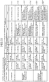
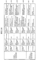
- Figs. 13 and 14 are tables showing a control example (non-revertive mode) when an equipment failure is detected in the optical network unit 52, which corresponds to Figs. 3 and 4 of the foregoing embodiment 1. It will be described in more detail.
- the 2-1 selector 82 and routing section 83 of the optical network unit 52, and the 2-1 selector 71 and routing section 72 of the optical line termination 51 operate on the working side.
- the selection controller 73 of the optical line termination 51 controls only the routing section 72, first, and transmits the K1 byte indicating "Acknowledgement" from the optical line termination 51 to the optical network unit 52 (S32 - S33).
- the selection controller 84 of the optical network unit 52 controls the 2-1 selector 82 and routing section 83 (S34), and finally the selection controller 73 of the optical line termination 51 controls the 2-1 selector 71 (S35).
- the optical line termination 51 maintains the state after having transmitted the K1 byte indicating "Acknowledgement” instead of "No switching request" to the optical network unit 52.
- the optical line termination 51 also transmits the K1 byte indicating "Acknowledgement” instead of "No switching request" to the optical network unit 52.
- the selection controller 73 of the optical line termination 51 also controls only the routing section 72, first, and the optical line termination 51 transmits the K1 byte indicating "Acknowledgement" to the optical network unit 52 (S37-S38).
- the selection controller 84 of the optical network unit 52 controls the 2-1 selector 82 and routing section 83 (S39), and finally, the selection controller 73 of the optical line termination 51 controls the 2-1 selector 71 (S40).
- the selection controller 73 in the optical network unit 52 operates similarly to S19 of Fig. 4:
- the optical line termination 51 transmits the K1 byte indicating "No switching request" to the optical network unit 52.
- the optical network unit 52 can transmit the K1 byte indicating "No switching request” or "Request to revert back to working side” instead of "Do not revert to working side” to the optical line termination 51 without providing any problem about the control.
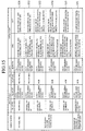
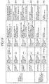
- Figs. 15 and 16 are tables showing a control example (revertive mode) when an equipment failure is detected in the optical network unit 52, which corresponds to Fig. 7 in the foregoing embodiment 2.
- stages S31-S35 which are identical to those of Fig. 13.
- the optical line termination 51 maintains the state after having transmitted the K1 byte indicating "Acknowledgement" instead of "No switching request" to the optical network unit 52.
- the selection controller 73 of the optical line termination 51 controls only the routing section 72, first, and the optical line termination 51 transmits the K1 byte indicating "No switching request" to the optical network unit 52 (S52).
- the selection controller 84 of the optical network unit 52 controls the 2-1 selector 82 and routing section 83 (S53), and finally, the selection controller 73 of the optical line termination 51 controls the 2-1 selector 71 (S54).
- the optical network unit 52 can transmit the K1 byte indicating "No switching request” instead of "Request to revert back to working side” to the optical line termination 51 without providing any problem about the control.
- Figs. 17 and 18 are tables showing a control example (non-revertive mode) when an equipment failure is detected in the optical network unit 52, which corresponds to Figs. 9 and 10 in the foregoing embodiment 3.
- the optical line termination 51 transmits at stages S36'-S37' the K1 byte indicating "Do not revert to working side” instead of "Acknowledgement" to the optical network unit 52.
- the optical network unit 52 can transmit the K1 byte indicating "No switching request” or "Request to revert back to working side” instead of "Do not revert to working side” to the optical line termination 51 without providing any problem with the control.
- Figs. 19 and 20 are tables showing a control example (revertive mode) when an equipment failure is detected in the optical network unit 52, which corresponds to Figs. 11 and 12 in the foregoing embodiment 3.
- the optical line termination 51 transmits at stages S51' the K1 byte indicating "Request to revert back to working side” instead of "Acknowledgement" to the optical network unit 52.
- the optical network unit 52 can transmit the K1 byte indicating "No switching request” instead of "Request to revert back to working side” to the optical line termination 51 without providing any problem with the control.
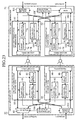
- Fig. 21 is a block diagram showing a detailed configuration of an embodiment 6 of the optical distribution network system in accordance with the present invention.
- the same reference numerals designate the same or like portions to those of Fig. 2, and hence the description thereof is omitted here.
- the reference numeral 101 designates a routing section for copying the traffic (downstream messages) to the working side line termination section of the OLT 61 and standby side line termination section of the OLT 62; and 102 designates a multiplexer (MUX) for multiplexing the traffic (upstream messages) supplied from the working side line termination section of the OLT 61 and standby side line termination section of the OLT 62.
- MUX multiplexer
- the reference numeral 103 designates a routing section for copying the traffic (upstream messages) to the working side line termination section of the ONU 63 and standby side line termination section of the ONU 64; and 104 designates a selection controller for bringing upstream messages to be transmitted from the TX/RX section 89 or 90 into a transmit stop state in accordance with the PLOAM grant generated by the grant generator 76 or 77 of the optical line termination 51.
- the basic operation of the present embodiment 6 is the same as that of the foregoing embodiment 1 except that the routing sections 101 and 103 each copy the messages rather than supply them to one of the two line terminations.
- the routing section 72 or 83 when the routing section 72 or 83 outputs the messages to one of the line terminations, they establish the route by rewriting a table (not shown) indicating the route.
- the table rewriting takes about 100 msec, thereby prolonging the switching of the system.
- the routing sections 101 and 103 of the present embodiment 6 always copy the messages, thus obviating the need for rewriting the table.
- the working side line termination section of the OLT 61 and standby side line termination section of the OLT 62 copy downstream messages to the working side line termination section of the ONU 63 and standby side line termination section of the ONU 64.
- the 2-1 selector 82 of the optical network unit 52 selects and outputs one of the downstream messages in response to the PST message consisting of the K1 byte and K2 byte.
- the selection controller 104 of the optical network unit 52 controls the TX/RX sections 89 and 90 with referring to the PLOAM grants, which are generated by the grant generators 76 and 77 of the optical line termination 51, and are transmitted along with the downstream message, thereby bringing the upstream message to be transmitted by the TX/RX section 89 or by the TX/RX section 90 into the transmit stop state.
- the selection controller 104 brings the upstream message to be transmitted from the standby side TX/RX section 90 into the transmit stop state.
- the selection controller 104 brings the upstream message to be transmitted from the working side TX/RX section 89 into the transmit stop state.
- the present embodiment 6 can obviate the need for the routing sections 101 and 103 to rewrite the table even if the system switching is carried out. As a result, the present embodiment 6 offers an advantage of being able to reduce the system switching time.
- Fig. 22 is a block diagram showing a detailed configuration of an embodiment 7 of the optical distribution network system in accordance with the present invention.
- the same reference numerals designate the same or like portions to those of Fig. 21, and hence the description thereof is omitted here.
- the selection controller 104 in the foregoing embodiment 6 controls the TX/RX sections 89 and 90 such that it brings the upstream message to be transmitted from the TX/RX section 89 or 90 into the transmit stop state
- the selection controller 105 in the present embodiment 7 carries out the ON/OFF operation of the gates 106 and 107 in response to the PST message consisting of the K1 byte and K2 byte such that it enables the TX/RX section 89 or 90 to transmit the upstream message.
- Fig. 23 is a block diagram showing a detailed configuration of an embodiment 8 of the optical distribution network system in accordance with the present invention.
- the same reference numerals designate the same or like portions to those of Fig. 21, and hence the description thereof is omitted here.
- the reference numeral 108 designates a selection controller for carrying out the ON/OFF operation of gates 109 and 110; 109 designates the gate for blocking the upstream message fed from the TX/RX section 78 in response to the OFF command supplied from the selection controller 108; and 110 designates the gate for blocking the upstream message fed from the TX/RX section 79 in response to the OFF command supplied from the selection controller 108.
- the selection controller 104 in the foregoing embodiment 6 controls the TX/RX sections 89 and 90 such that it brings the upstream message to be transmitted from the TX/RX section 89 or 90 into the transmit stop state
- the selection controller 108 in the present embodiment 8 carries out the ON/OFF operation of the gates 109 and 110 such that it enables only the message received by the TX/RX section 78 or 79 to be transmit from the MUX 102.
- the foregoing embodiments 6-8 carry out the system switching by controlling the TX/RX sections 89 and 90, the gates 106 and 107, or the gates 109 and 110.
- the working side is switched to the standby side, it is not unlikely that the upstream message received by the standby side TX/RX section 79 of the optical line termination 51 is supplied to the MUX 102 before the entire upstream message, which is received by the working side TX/RX section 78 before the switching, has been supplied to the MUX 102.
- the present embodiment 9 prevents the message of the newly selected system from being output until a predetermined time has elapsed after the system switching.
- the selection controller 108 of the optical line termination 51 controls the TX/RX section 79 or the gate 110 until the predetermined time has elapsed after the completion of the system switching, thereby preventing the upstream message, which is received by the standby side TX/RX section 79, to be supplied to the MUX 102.
- the present embodiment 9 can prevent the collision of the working side upstream message and the standby side upstream message.
- the predetermined time of an order of a few hundred microseconds is enough for the operation, it presents no problem in reducing the system switching time. By way of comparison, it takes about one hundred milliseconds for the routing sections 72 and 83 to rewrite the table in the foregoing embodiment 1.
Landscapes
- Engineering & Computer Science (AREA)
- Computer Networks & Wireless Communication (AREA)
- Optical Communication System (AREA)
- Data Exchanges In Wide-Area Networks (AREA)
- Small-Scale Networks (AREA)
- Maintenance And Management Of Digital Transmission (AREA)
- Monitoring And Testing Of Transmission In General (AREA)
Abstract
Description
Claims (14)
- An optical distribution network system comprising:an optical line termination (51);a plurality of optical network units (52), each of which is connected to said optical line termination through at least one of a first optical network and a second optical network;monitoring means (61, 62) installed in said optical line termination for detecting a system switching request from each of said plurality of optical network units; andcontrol means (73) installed in said optical line termination for controlling system switching between a working side and a standby side of each of said plurality of optical network units.
- The optical distribution network system according to claim 1, wherein said control means employs a tree switching method that carries out the system switching between the working side and the standby side of all of said plurality of optical network units at once, when carrying out the system switching of any one of said plurality of optical network units.
- The optical distribution network system according to claim 1, wherein said control means employs a branch switching method that carries out the system switching between the working side and the standby side of only one of said plurality of optical network units, when carrying out the system switching.
- The optical distribution network system according to claim 2, wherein when said monitoring means detects a system switching request sent from at least one of said plurality of optical network units, said control means makes a decision as to whether to carry out the system switching considering failure conditions of all of said plurality of optical network units.
- The optical distribution network system according to claim 4, wherein when carrying out the system switching of the working side of all of said plurality of optical network units to their standby side, said control means performs switching control only when a number of failed units on the standby side is less than a number of failed units on the working side.
- The optical distribution network system according to claim 4, wherein when carrying out the system switching of the standby side of all of said plurality of optical network units to their working side, said control means performs switching control only when a number of failed units on the working side is less than a number of failed units on the standby side.
- The optical distribution network system according to any one of claims 1-6, wherein each of said plurality of optical network units further comprises switching means for carrying out the system switching between the working side and the standby side when it receives a system switching command from said optical line termination.
- The optical distribution network system according to any one of claims 1-7, wherein said control means carries out the system switching only when a system switching request from one of said plurality of optical network units continues for more than a predetermined time period.
- The optical distribution network system according to any one of claims 1-8, wherein said control means carries out its switching control in a duplex optical distribution network system on a passive optical network system.
- The optical distribution network system according to any one of claims 1-9, wherein said optical line termination further comprises output selecting means (108-110) for outputting one of upstream messages that are copied via the working side and the standby side by at least one of said plurality of optical network units, and wherein at least one of said plurality of optical network units further comprises output selecting means (105-107) for outputting one of downstream messages that are copied via the working side and the standby side by said optical line termination.
- The optical distribution network system according to claim 10, wherein at least one of said plurality of optical network units comprises transmission stop means (104) for halting transmission of one of the upstream messages to be copied to the working side and standby side of said optical line termination.
- The optical distribution network system according to claim 10, wherein at least one of said plurality of optical network units comprises a gate (106 or 107) for preventing one of the messages to be copied from being copied by suppressing it.
- The optical distribution network system according to claim 10, wherein the optical line termination comprises a gate (109 or 110) for preventing one of the messages to be copied from being copied by suppressing it.
- The optical distribution network system according to claim 10, wherein said control means prevents the message of the selected side from being output until a predetermined time has elapsed after the system switching.
Applications Claiming Priority (4)
| Application Number | Priority Date | Filing Date | Title |
|---|---|---|---|
| JP2000267606 | 2000-09-04 | ||
| JP2000267606 | 2000-09-04 | ||
| JP2000382614 | 2000-12-15 | ||
| JP2000382614A JP2002152135A (en) | 2000-09-04 | 2000-12-15 | Optical multi-branch communication system |
Publications (2)
| Publication Number | Publication Date |
|---|---|
| EP1185129A2 true EP1185129A2 (en) | 2002-03-06 |
| EP1185129A3 EP1185129A3 (en) | 2006-03-29 |
Family
ID=26599204
Family Applications (1)
| Application Number | Title | Priority Date | Filing Date |
|---|---|---|---|
| EP01120078A Withdrawn EP1185129A3 (en) | 2000-09-04 | 2001-08-21 | Optical distribution network system that performs system switching only when total operation condition is improved |
Country Status (3)
| Country | Link |
|---|---|
| US (1) | US20020030865A1 (en) |
| EP (1) | EP1185129A3 (en) |
| JP (1) | JP2002152135A (en) |
Cited By (2)
| Publication number | Priority date | Publication date | Assignee | Title |
|---|---|---|---|---|
| EP1241836A4 (en) * | 2000-12-15 | 2005-06-01 | Mitsubishi Electric Corp | MULTI-CHANNEL OPTICAL COMMUNICATION SYSTEM |
| WO2011131141A1 (en) * | 2010-04-22 | 2011-10-27 | Huawei Technologies Co., Ltd. | Ethod for authentication of a wireless backup system for an optical network unit |
Families Citing this family (22)
| Publication number | Priority date | Publication date | Assignee | Title |
|---|---|---|---|---|
| US7181142B1 (en) | 2002-04-09 | 2007-02-20 | Time Warner Cable Inc. | Broadband optical network apparatus and method |
| US7313330B2 (en) | 2002-08-13 | 2007-12-25 | Samsung Electronics Co., Ltd. | Redundant apparatus and method for gigabit ethernet passive optical network system and frame format thereof |
| KR100575945B1 (en) * | 2003-08-26 | 2006-05-02 | 삼성전자주식회사 | Gigabit Ethernet Subscriber Network with Dual Link Structure and Dual Link Setting Method |
| US7835381B1 (en) * | 2004-01-09 | 2010-11-16 | Cisco Technology, Inc. | Providing point to multi-point communication for digital subscriber loops |
| JP2006050092A (en) * | 2004-08-02 | 2006-02-16 | Pacific Ind Co Ltd | Optical lan system |
| EP1653641B1 (en) * | 2004-10-29 | 2010-12-15 | Alcatel Lucent | Optical access node |
| KR100833504B1 (en) * | 2006-12-05 | 2008-05-29 | 한국전자통신연구원 | PON partial double protection switching device and method using single splitter |
| US8861952B2 (en) * | 2007-02-28 | 2014-10-14 | Finisar Corporation | Redundancy and interoperability in multi-channel optoelectronic devices |
| WO2008134750A2 (en) * | 2007-04-30 | 2008-11-06 | Finisar Corporation | Eye safety and interoperability of active cable devices |
| WO2008146344A1 (en) | 2007-05-25 | 2008-12-04 | Mitsubishi Electric Corporation | Optical access network |
| US8582966B2 (en) * | 2007-09-10 | 2013-11-12 | Cortina Systems, Inc. | Method and apparatus for protection switching in passive optical network |
| US8538256B2 (en) * | 2008-03-17 | 2013-09-17 | Telefonaktiebolaget L M Ericsson (Publ) | Fast protection scheme for passive optical network |
| WO2009116904A1 (en) * | 2008-03-17 | 2009-09-24 | Telefonaktiebolaget L M Ericsson (Publ) | Immediate protection scheme for passive optical network |
| JP4961379B2 (en) * | 2008-03-31 | 2012-06-27 | 株式会社日立製作所 | Network system and communication device |
| AU2009237405B2 (en) | 2008-04-16 | 2013-09-26 | Telefonaktiebolaget L M Ericsson (Publ) | Connectivity fault management traffic indication extension |
| US9319758B2 (en) * | 2008-10-21 | 2016-04-19 | Broadcom Corporation | Method and system for protection switching in ethernet passive optical networks |
| JP2011091657A (en) * | 2009-10-23 | 2011-05-06 | Hitachi Ltd | Optical transmission system |
| CN105659512B (en) * | 2013-10-25 | 2018-01-02 | 日本电信电话株式会社 | Optical communication system and optic communication abnormal restoring method |
| US20150188625A1 (en) * | 2013-12-27 | 2015-07-02 | Electronics And Telecommunications Research Institute | Method for realizing time reduction in shared mesh network |
| US9948399B2 (en) | 2015-01-09 | 2018-04-17 | Time Warner Cable Enterprises Llc | Methods and apparatus for removing beat interference from splitters/combiners |
| US9674591B2 (en) | 2015-06-08 | 2017-06-06 | Time Warner Cable Enterprises Llc | Methods and apparatus for asymmetric distribution of mixed content via a network |
| AU2017260108B2 (en) * | 2016-05-04 | 2021-08-26 | Adtran, Inc. | Systems and methods for performing optical line terminal (OLT) failover switches in optical networks |
Family Cites Families (5)
| Publication number | Priority date | Publication date | Assignee | Title |
|---|---|---|---|---|
| GB2272608B (en) * | 1992-11-12 | 1996-10-09 | Northern Telecom Ltd | Telecommunications systems |
| EP0700605B1 (en) * | 1993-05-28 | 1998-08-05 | Siemens Aktiengesellschaft | Equivalent circuit process for a transmission device for the bidirectional transmission of digital signals and arrangement for implementing the process |
| US5539564A (en) * | 1993-09-22 | 1996-07-23 | Nippon Telegraph And Telephone Corporation | Point-to-multipoint optical transmission system |
| CN1150514A (en) * | 1994-06-08 | 1997-05-21 | 英国电讯有限公司 | Access Network |
| JPH11122172A (en) * | 1997-10-20 | 1999-04-30 | Fujitsu Ltd | Optical subscriber network system |
-
2000
- 2000-12-15 JP JP2000382614A patent/JP2002152135A/en active Pending
-
2001
- 2001-08-21 EP EP01120078A patent/EP1185129A3/en not_active Withdrawn
- 2001-08-31 US US09/942,567 patent/US20020030865A1/en not_active Abandoned
Cited By (4)
| Publication number | Priority date | Publication date | Assignee | Title |
|---|---|---|---|---|
| EP1241836A4 (en) * | 2000-12-15 | 2005-06-01 | Mitsubishi Electric Corp | MULTI-CHANNEL OPTICAL COMMUNICATION SYSTEM |
| US7496294B2 (en) | 2000-12-15 | 2009-02-24 | Mitsubishi Denki Kabushiki Kaisha | Optical multi-branch communication system |
| WO2011131141A1 (en) * | 2010-04-22 | 2011-10-27 | Huawei Technologies Co., Ltd. | Ethod for authentication of a wireless backup system for an optical network unit |
| US9185555B2 (en) | 2010-04-22 | 2015-11-10 | Futurewei Technologies, Inc. | Method for authentication of a wireless backup system for an optical network unit |
Also Published As
| Publication number | Publication date |
|---|---|
| EP1185129A3 (en) | 2006-03-29 |
| US20020030865A1 (en) | 2002-03-14 |
| JP2002152135A (en) | 2002-05-24 |
Similar Documents
| Publication | Publication Date | Title |
|---|---|---|
| EP1185129A2 (en) | Optical distribution network system that performs system switching only when total operation condition is improved | |
| EP0217490B1 (en) | Communications system with protection switching using channel identities and individual selectors | |
| CA2130067C (en) | Ring interworking between bidirectional line-switched ring transmission systems | |
| US6701085B1 (en) | Method and apparatus for data transmission in the wavelength-division multiplex method in an optical ring network | |
| CA2130066C (en) | Ring interworking between bidirectional line-switched ring transmission systems and path-switched ring transmission systems | |
| US6288809B1 (en) | Optical subscriber network system | |
| AU743041B2 (en) | Method and arrangement for transmitting data in a ring network | |
| US8600229B2 (en) | Method and system for shared protection in wavelength division multiplexing loop network | |
| US6980711B2 (en) | Automatically switched redundant switch configurations | |
| US4837760A (en) | Communications system with protection switching using individual selectors | |
| JPH0618378B2 (en) | Ring type signal transmission network | |
| CA2355564A1 (en) | Optical distribution network system with large usable bandwidth for dba | |
| US7313088B2 (en) | Common protection architecture for optical network | |
| CA2078533C (en) | Optical communications system having transmission line switching system | |
| US7546034B2 (en) | Circuit arrangement for line protection of optical data transmission | |
| EP1195939A1 (en) | Redundant optical multiple-branch communication system | |
| EP0624992A2 (en) | In-service upgrade for a telecommunication system | |
| JP2003092583A (en) | Passive optical network system that can effectively use communication bandwidth | |
| US6385165B1 (en) | Add-drop multiplexer of duplicated configuration having increased transport capacity | |
| WO1993022859A1 (en) | Method and device for configuration of a time-space-time cross-connection at occasions when the need of cross-connexion changes and use thereof | |
| US6741812B2 (en) | Synchronous digital communications system | |
| US7496294B2 (en) | Optical multi-branch communication system | |
| US6680905B1 (en) | Transfer path control system | |
| JP2000041271A (en) | Method and device for executing switching by using group signal state padding signal | |
| US7158720B1 (en) | Optical shared protection ring for multiple spans |
Legal Events
| Date | Code | Title | Description |
|---|---|---|---|
| PUAI | Public reference made under article 153(3) epc to a published international application that has entered the european phase |
Free format text: ORIGINAL CODE: 0009012 |
|
| AK | Designated contracting states |
Kind code of ref document: A2 Designated state(s): AT BE CH CY DE DK ES FI FR GB GR IE IT LI LU MC NL PT SE TR |
|
| AX | Request for extension of the european patent |
Free format text: AL;LT;LV;MK;RO;SI |
|
| PUAL | Search report despatched |
Free format text: ORIGINAL CODE: 0009013 |
|
| AK | Designated contracting states |
Kind code of ref document: A3 Designated state(s): AT BE CH CY DE DK ES FI FR GB GR IE IT LI LU MC NL PT SE TR |
|
| AX | Request for extension of the european patent |
Extension state: AL LT LV MK RO SI |
|
| RIC1 | Information provided on ipc code assigned before grant |
Ipc: H04Q 11/04 20060101ALI20060203BHEP Ipc: H04Q 11/00 20060101AFI20060203BHEP |
|
| RAP1 | Party data changed (applicant data changed or rights of an application transferred) |
Owner name: MITSUBISHI DENKI KABUSHIKI KAISHA |
|
| 17P | Request for examination filed |
Effective date: 20060512 |
|
| AKX | Designation fees paid |
Designated state(s): DE FR GB |
|
| STAA | Information on the status of an ep patent application or granted ep patent |
Free format text: STATUS: THE APPLICATION HAS BEEN WITHDRAWN |
|
| 18W | Application withdrawn |
Effective date: 20061219 |