EP1185009A2 - Leak power ratio detection circuit, mobile communication terminal, and control circuit for mobile communication terminal - Google Patents
Leak power ratio detection circuit, mobile communication terminal, and control circuit for mobile communication terminal Download PDFInfo
- Publication number
- EP1185009A2 EP1185009A2 EP01120618A EP01120618A EP1185009A2 EP 1185009 A2 EP1185009 A2 EP 1185009A2 EP 01120618 A EP01120618 A EP 01120618A EP 01120618 A EP01120618 A EP 01120618A EP 1185009 A2 EP1185009 A2 EP 1185009A2
- Authority
- EP
- European Patent Office
- Prior art keywords
- level
- detection means
- power
- filter
- radio frequency
- Prior art date
- Legal status (The legal status is an assumption and is not a legal conclusion. Google has not performed a legal analysis and makes no representation as to the accuracy of the status listed.)
- Granted
Links
Images




Classifications
-
- H—ELECTRICITY
- H04—ELECTRIC COMMUNICATION TECHNIQUE
- H04W—WIRELESS COMMUNICATION NETWORKS
- H04W52/00—Power management, e.g. Transmission Power Control [TPC] or power classes
- H04W52/04—Transmission power control [TPC]
- H04W52/06—TPC algorithms
-
- H—ELECTRICITY
- H03—ELECTRONIC CIRCUITRY
- H03G—CONTROL OF AMPLIFICATION
- H03G3/00—Gain control in amplifiers or frequency changers
- H03G3/20—Automatic control
- H03G3/30—Automatic control in amplifiers having semiconductor devices
- H03G3/3036—Automatic control in amplifiers having semiconductor devices in high-frequency amplifiers or in frequency-changers
- H03G3/3042—Automatic control in amplifiers having semiconductor devices in high-frequency amplifiers or in frequency-changers in modulators, frequency-changers, transmitters or power amplifiers
-
- H—ELECTRICITY
- H04—ELECTRIC COMMUNICATION TECHNIQUE
- H04B—TRANSMISSION
- H04B1/00—Details of transmission systems, not covered by a single one of groups H04B3/00 - H04B13/00; Details of transmission systems not characterised by the medium used for transmission
- H04B1/38—Transceivers, i.e. devices in which transmitter and receiver form a structural unit and in which at least one part is used for functions of transmitting and receiving
- H04B1/40—Circuits
- H04B1/50—Circuits using different frequencies for the two directions of communication
- H04B1/52—Hybrid arrangements, i.e. arrangements for transition from single-path two-direction transmission to single-direction transmission on each of two paths or vice versa
- H04B1/525—Hybrid arrangements, i.e. arrangements for transition from single-path two-direction transmission to single-direction transmission on each of two paths or vice versa with means for reducing leakage of transmitter signal into the receiver
-
- H—ELECTRICITY
- H04—ELECTRIC COMMUNICATION TECHNIQUE
- H04B—TRANSMISSION
- H04B17/00—Monitoring; Testing
- H04B17/30—Monitoring; Testing of propagation channels
- H04B17/309—Measuring or estimating channel quality parameters
- H04B17/354—Adjacent channel leakage power
-
- H—ELECTRICITY
- H04—ELECTRIC COMMUNICATION TECHNIQUE
- H04W—WIRELESS COMMUNICATION NETWORKS
- H04W52/00—Power management, e.g. Transmission Power Control [TPC] or power classes
- H04W52/04—Transmission power control [TPC]
- H04W52/06—TPC algorithms
- H04W52/16—Deriving transmission power values from another channel
Definitions
- the present invention relates to a leak power ratio detection circuit for detecting an adjacent channel leak power ratio of a radio signal transmitted from, for example, a CDMA (Code Division Multiple Access) type mobile communication terminal.
- CDMA Code Division Multiple Access
- Amplitude modulation components are processed in uplink modulation methods of modern digital mobile communication systems, such as ⁇ /4 shift QPSK applied to PDC (Personal Digital Cellular) systems, OQPSK applied to cdmaOne systems, and HPSK applied to W-CDMA systems and cdma2000 systems.
- PDC Personal Digital Cellular
- OQPSK Orthogonal Digital Cellular
- HPSK HPSK applied to W-CDMA systems and cdma2000 systems.
- a transmission power amplifier in the mobile communication terminal of this type is required to linearly amplify a transmission signal waveform including an amplitude variation component.
- the power consumption of the transmission power amplifier is disadvantageously increased in order to keep the linearity.
- the terminal transmission power is lowered because the mobile communication terminal is present near a base station, most of the power supplied from a cell to the power amplifier will be wasted.
- Another possible method is to extract an adjacent channel leak power component from a radio transmission output signal using a filter, measure the level of the extracted leak power component, calculate a ratio between this level and the transmission output level to find an adjacent channel leak power ratio, and properly reduce the supply power to the power amplifier using information of this ratio.
- the frequency channel to be used is changed depending on cases.
- the center frequency of the aforementioned filter needs to be so varied as to be able to extract adjacent channel leak power components in association with all possible radio frequency channels. It is difficult to realize such a filter in the mobile communication terminal.
- An object of the present invention is to provide a leak power ratio detection circuit capable of detecting an adjacent channel leak power ratio irrespective of a radio frequency channel used, with an easily realizable structure.
- Another object of the invention is to provide a mobile communication terminal capable of reducing power consumption by always operating a power amplifier with a minimum necessary supply power.
- the present invention provides a leak power ratio detection circuit for detecting a leak power to an adjacent channel of a radio frequency signal produced by a transmission circuit including at least power amplifier means for power amplification of the radio frequency signal, the leak power ratio detection circuit comprising: squaring means for squaring the radio frequency signal produced by the transmission circuit and producing a low-frequency component; a first filter for extracting a spectrum component corresponding to a desired channel, from that portion of the low-frequency component of the squared result obtained by the squaring means, which occurs with a center thereof being present near a DC; a second filter for extracting, from the squared result of the squaring means, a spectrum component corresponding to spectrum spreading due to a distortion in the transmission circuit; and leak power ratio detection means for detecting a ratio of the leak power to the adjacent channel of the radio frequency signal, on the basis of a level of the spectrum component extracted by the first filter and a level of the spectrum component extracted by the second filter.
- the radio frequency signal is squared by the squaring means.
- the ratio of leak power to the adjacent channel is detected on the basis of the low-frequency spectrum component of the squared result of the squaring means, which has a center at the DC and has correlation with the spectrum of the desired channel, and the spectrum component corresponding to the spectrum spreading due to the distortion in the transmission circuit.
- the adjacent channel leak power ratio can be detected on the basis of the analysis of the level of the spectrum in the low-frequency region, irrespective of the frequency of the channel used. Therefore, this invention can be easily realized.
- the invention also provides a mobile communication terminal having, in a transmission system, power amplifier means for power-amplifying at least a radio frequency signal, the terminal comprising: branching means for branching a portion of the power-amplified radio frequency signal produced by the power amplifier means; squaring means for squaring the radio frequency signal branched by the branching means and producing a low-frequency component; a first filter for extracting a spectrum component corresponding to a desired channel, from that portion of the low-frequency component of the squared result obtained by the squaring means, which occurs with a center thereof being present near a DC; a second filter for extracting, from the squared result of the squaring means, a spectrum component corresponding to spectrum spreading due to a distortion in the transmission system; leak power ratio detection means for detecting a ratio of a leak power to an adjacent channel of the radio frequency signal, on the basis of a level of the spectrum component extracted by the first filter and a level of the spectrum component extracted by the second filter; and power
- the invention also provides a control circuit for a mobile communication terminal having, in a transmission system, power amplifier means for power-amplifying at least a radio frequency signal, the terminal comprising: branching means for branching a portion of the power-amplified radio frequency signal produced by the power amplifier means; squaring means for squaring the radio frequency signal branched by the branching means and producing a low-frequency component; a first filter for extracting a spectrum component corresponding to a desired channel, from that portion of the low-frequency component of the squared result obtained by the squaring means, which occurs with a center thereof being present near a DC; a second filter for extracting, from the squared result of the squaring means, a spectrum component corresponding to spectrum spreading due to a distortion in the transmission system; leak power ratio detection means for detecting a ratio of a leak power to an adjacent channel of the radio frequency signal, on the basis of a level of the spectrum component extracted by the first filter and a level of the spectrum component extracted by the second filter; and
- the radio frequency signal is squared by the squaring means.
- the ratio of leak power to the adjacent channel is detected on the basis of the low-frequency spectrum component of the squared result of the squaring means, which has a center at the DC and has correlation with the spectrum of the desired channel, and the spectrum component corresponding to the spectrum spreading due to the distortion in the transmission circuit.
- the supply power to the power amplifier means is controlled so as to make the detected ratio of the leak power coincide with a predetermined level.
- the power amplifier can always be operated with a minimum necessary supply power, and the power consumption can be reduced.
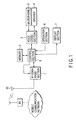
- FIG. 1 shows the structure of a mobile radio terminal according to an embodiment of the present invention, as well as a mobile communication system to which the mobile radio terminal is applied.
- the mobile radio terminal is wirelessly connected to a base station BS of the mobile communication system, and communicates with some other communication station via a mobile communication network.
- W-CDMA Wideband Code Division Multiple Access
- a high-rate, large-volume multimedia mobile communication is carried out using, e.g. a 5 MHz bandwidth in a 2 GHz band.
- Mobile radio terminals are discretely disposed within a service area and perform communication in synchronism with the base station BS connected to a public network.
- a W-CDMA radio section 1 transmits and receives CDMA signals via an antenna 50 with a base station BS according to the W-CDMA method.
- the W-CDMA radio section 1 receives coded data from a voice CODEC section 2 via a control section 8, and transmits the coded data.
- the W-CDMA radio section 1 receives coded data and delivers it to the voice CODEC section 2 via the control section 8.
- the chip rate of spread codes is set at 4.096 Mcps, and a QPSK method is used as a first-order modulation method.
- the voice CODEC section 2 encodes a transmission voice signal input from a microphone 3 according to a predetermined voice encoding method and passes the coded signal to the W-CDMA radio section 1 via the control section 8. In addition, the voice CODEC section 2 decodes the coded data input from the W-CDMA radio section 1 via the control section 8 and converts it to a reception signal. The reception signal is output from a loudspeaker 4 with amplified magnitude.
- a memory 5 comprises a semiconductor memory such as a RAM or a ROM.
- the memory 5 stores control programs for the control section 8.
- the memory 5 stores, for instance, menu image data to be displayed on a display section 7.
- An operation section 6 is a key input section comprising numeral keys, 4-direction keys, and various function keys.
- the operation section 6 receives a user's instructions on ordinary call transmission/reception, scrolling of information displayed on the display section 7, and the like.
- the display section 7 comprises an LCD (Liquid Crystal Display), a plasma display, or the like.
- the control section 8 controls the respective sections of the mobile radio terminal. Specifically, the control section 8 performs controls relating to, e.g. radio communication via the mobile communication network, and display on the display section 7.
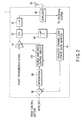
- FIG. 2 shows the antenna 50 and a transmission system of the W-CDMA radio section 1.
- a radio transmission signal is obtained by frequency-converting a transmission signal to a radiofrequency signal by means of a frequency converter (not shown).
- a power amplifier (PA) 10 is supplied with power that is controlled by a power amplifier control circuit 100 (to be described below). The power amplifier 10 amplifies the radio transmission signal in accordance with the supplied power.
- the amplified radio transmission signal is radiated to the space from the antenna 50 via a directional coupler (CPL) 20, an isolator 30 and a duplexer 40.
- CPL directional coupler
- the directional coupler 20 branches only a small portion of a predetermined ratio of the radio transmission signal and delivers it to a variable attenuator 60.
- variable attenuator 60 adjusts the level of the radio transmission signal input from the directional coupler 20, and outputs the level-adjusted signal to an adjacent channel leak power ratio monitor 70.
- the adjacent channel leak power ratio monitor 70 detects, as a substitute monitor value, a ratio of a leak power to an adjacent channel, which is possessed by the radio transmission signal to be emitted from the antenna 50.
- the detected substitute monitor value is input to a subtracter 80.
- the subtracter 80 finds a difference between the substitute monitor value and a reference value (ACPR_REF) that is a target value of the adjacent channel leak power ratio.
- the reference value is provided from the control section 8.
- An integrator 90 accumulates the difference found by the subtracter 80 for a predetermined time period and outputs the accumulated difference.
- the power amplifier control circuit 100 controls the supply power from a battery to the power amplifier 10 so that the power level of the radio transmission signal amplified by the power amplifier 10 may reach a predetermined level.
- the level-adjusted radio transmission signal from the variable attenuator 60 is input to a squaring circuit (X 2 ) 71 and is thereby squared.
- FIG. 4 shows an example of the structure of the squaring circuit 71.
- the squaring circuit 71 shown in FIG. 4 includes a multiplier circuit.
- a circuit portion comprising transistors Q1, Q2, Q3, Q4, Q5 and Q6 constitutes a well-known Gilbert-type multiplier circuit.
- the bases of transistors Q2, Q3 and Q6 are AC-grounded.
- An input signal from an input terminal (INPUT) i.e. the output from the attenuator 60
- INPUT input terminal
- OUTPUT output terminals
- negative feedback technologies or pre-distortion technologies may be used to increase the input voltage range, as described in the above-mentioned publication.
- the radio transmission signals squared by the squaring circuit 71 are output to band-pass filters (BPF) 72 and 73.
- BPF band-pass filters
- the band-pass filter 72 extracts a spectrum component corresponding to a desired channel, from that low-frequency component of the output of the squaring circuit 71, which occurs at low frequencies with a center thereof being present near a DC (Direct Current).
- the band-pass filter 73 extracts, from the output of the squaring circuit 71, a spectrum component that corresponds to spectrum spreading due to distortion in the transmission system.
- the band-pass filter 72 may theoretically be a low-pass filter. However, if consideration is given to elimination of the effect of DC offset occurring in the squaring circuit 71, it is desirable that the band-pass filter 72 be a band-pass filter having a pass band necessary for extracting a component corresponding to a modulation signal.
- a level measuring circuit (LEVEL) 74 measures a signal level of the spectrum component extracted by the band-pass filter 72.
- a level measuring circuit (LEVEL) 75 measures a signal level of the spectrum component extracted by the band-pass filter 73.
- a level ratio measuring circuit (RATIO) 76 measures a ratio between the level measured by the level measuring circuit 74 and the level measured by the level measuring circuit 75, and outputs a measured result to the subtracter 80 as the aforementioned substitute monitor value.
- FIG. 5 shows an example of structures of the level measuring circuits 74 and 75 and level ratio measuring circuit 76.
- an RMStoDC circuit (RMStoDC) 74a corresponds the level measuring circuit 74
- an RMStoDC circuit (RMStoDC) 75a corresponds the level measuring circuit 75
- a division circuit ( ⁇ ) 76a corresponds to the level ratio measuring circuit 76.
- the RMStoDC circuits (RMStoDC) 74a and 75a are circuits for outputting effective values of the input signals as DC signals. Their functions are realized, for instance, by IC products "AD8361” marketed by Analog Devices Corp.
- the division circuit 76a is a division circuit for outputting a division result of the two inputs.
- This function is realized, for instance, by an analog multiplier IC "NJM4200” marketed by Kabushiki-kaisha Shin-Nippon Musen. This company publishes "Bi-polar IC Data Book '94 (Audio/Vide/Communication/Special Edition),” in which the method of constructing this device is described in detail (pp. 7-130).
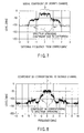
- FIG. 6 shows characteristics of a radio transmission signal input to the squaring circuit 71 in a case where no distortion is caused by the transmission system.
- FIG. 6 shows a spectrum of the radio transmission signal, with the abscissa indicating a detuning frequency from a carrier frequency (i.e. a frequency detuned from a carrier frequency).
- a component near ⁇ 5 MHz is caused by sampling in a process of generating a transmission signal in a base band. This component can easily be removed by a filter, and no problem will arise.
- FIG. 7 shows characteristics in a case where distortion is caused by the transmission system.
- FIG. 7, like FIG. 6, shows a spectrum of the radio transmission signal, with the abscissa indicating a detuning frequency from a carrier frequency.
- FIG. 7 shows a spectrum with distortion caused by the amplifier of the transmission system having third-order mutual modulation distortion (IP3) characteristics. It is understood that the spectrum is spread due to distortion.
- IP3 third-order mutual modulation distortion
- This kind of distortion will significantly occur in a circuit using high-power signals, such as the power amplifier 10.
- the spreading of the spectrum causes interference with a user who is using an adjacent frequency for communication.
- a power ratio between the spreading portion of the spectrum and a spectrum portion associated with a desired channel is strictly specified as an adjacent channel leak power ratio.
- FIG. 8 shows characteristics of the radio transmission signal with distortion, which has been squared by the squaring circuit 71.
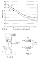
- FIG. 9 shows a variation C1 in power ratio between the spectrum of the desired channel and the spreading portion of the spectrum due to distortion in FIG. 7, and a variation C2 in power ratio between the spectrum corresponding to the desired channel and the component corresponding to the spreading of the spectrum due to distortion in FIG. 8, in a case where the distortion characteristics of the power amplifier 10 causing distortion in the radio transmission signal, that is, the third-order mutual modulation characteristics, are varied.
- a substitute monitor value for the adjacent channel leak power ratio at the radio frequency can be found if the power ratio between the spectrum component corresponding to the desired channel and the component corresponding to the spreading of the spectrum due to distortion in FIG. 8 is found by the adjacent channel leak power ratio monitor 70 having the structure shown in FIG. 3.
- the radio transmission signals squared by the squaring circuit 71 are output to the band-pass filters 72 and 73.
- the band-pass filter 72 extracts a spectrum component S0, which corresponds to the desired channel, from the component occurring near the DC.
- the band-pass filter 73 extracts a spectrum component Sd that corresponds to spectrum spreading due to distortion.
- the level measuring circuit 74 measures the signal level of the spectrum component S0 extracted by the band-pass filter 72.
- the level measuring circuit 75 measures the signal level of the spectrum component Sd extracted by the band-pass filter 73.
- the level ratio measuring circuit 76 measures the ratio between the level of the spectrum component S0 corresponding to the desired channel and the level of the component Sd corresponding to the spectrum spreading due to distortion, and outputs a measured result to the subtracter 80 as the substitute monitor value.
- the substitute monitor value measured by the adjacent channel leak power ratio monitor 70 increases. As a result, the output from the subtracter 80 takes a positive value, and positive values are accumulated in the integrator 90.
- the power amplifier control circuit 100 functions to reduce the battery supply power to the power amplifier 10. With this control operation, the power amplifier 10 operates under the condition of low power consumption.
- the adjacent channel leak power ratio of the radio transmission signal will ultimately converge at a value corresponding to ACPR_REF.
- the reference value (ACPR_REF) may be a fixed value or a variable value varying according to the transmission output level.
- the radio transmission signal is squared by the squaring circuit 71, and the ratio of leak power to the adjacent channel is detected on the basis of the low-frequency spectrum component having a center near the DC and correlation with the spectrum of the desired channel, and the spectrum component corresponding to the spreading of the spectrum due to the distortion of the transmission system.
- the adjacent channel leak power ratio can be detected by the analysis of the level of the spectrum at the low-frequency region, irrespective of the radio frequency channel.
- the ratio of leak power to the adjacent channel can be easily measured. Based on the measured ratio, the battery supply power to the power amplifier 10 can always be set at a minimum necessary level, and the power consumption can be reduced.
- the present invention is not limited to the above embodiment.
- the structure of the squaring circuit 71 in the above embodiment is not limited to that shown in FIG. 4.
- the squaring circuit 71 may have a structure shown in FIG. 10.
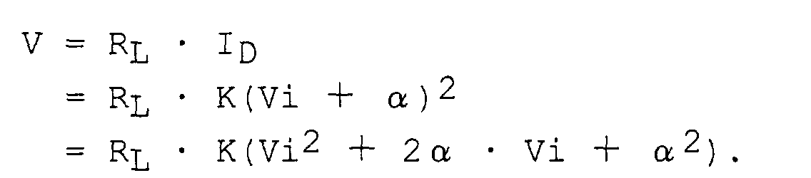
- the squaring circuit shown in FIG. 10 uses a MOS transistor as a non-linear element having a second-order distortion coefficient.
- I D K(V GS - V T ) 2
- the MOS transistor is described as the non-linear device having the second-order distortion coefficient.
- the same advantage can be obtained with use of any type of non-linear device having a second-order distortion coefficient.
- the level measuring circuits 74 and 75 and level ratio measuring circuit 76 having the structures shown in FIG. 5 are used. Alternatively, these circuits may have structures as shown in FIG. 11.
- a Log_Amp circuit (Log_Amp) 74b corresponds to the level measuring circuit 74
- a Log_Amp circuit (Log_Amp) 75b corresponds to the level measuring circuit 75
- a subtracter (+) 76b corresponds to the level ratio measuring circuit 76.
- the Log_Amp circuits 74b and 75b are Log_Amp circuits for logarithmically compressing the input signal levels and outputting DC signals. These functions are realized, for example, by IC products "AD9310" marketed by Analog Devices Corp.
- the subtracter 76b is a subtracter circuit for outputting a result of the subtraction between two inputs, and it can easily be constructed using an operational amplifier.
- the level ratio measuring circuit 76 may comprise a simple subtracter circuit and can advantageously be constructed with simple structure.
- an A/D converter (A to D) 110 may be added, and the adjacent channel leak power ratio monitor 70 may be constructed to derive an output from the level measuring circuit 74, as shown in FIG. 13.
- the output of the level measuring circuit 74 is converted to a digital value by the A/D converter 110.
- a control section 8 for controlling the entirety of the mobile communication terminal may control the upper limit of the gain of the transmission system so that the gain may not exceed a tolerable maximum transmission power level.
- the attenuator 60 is not necessarily required if the adjacent channel leak power ratio monitor 70 has a sufficiently wide input level tolerable range from the viewpoint of circuitry, and if the radio transmission signal branched from the directional coupler 20 falls within the input level tolerable range of the adjacent channel leak power ratio monitor 70 from the viewpoint of circuitry.
- the attenuator 60 may be replaced with an attenuator having a fixed value.
- the supply power to the power amplifier 10 is continuously controlled making use of the output of the adjacent channel leak power ratio monitor 70.
- the output of the adjacent channel leak power ratio monitor 70 may be A/D converted.
- the result of conversion is input to the control section 8.
- the control section 8 realizes the functions of the subtracter 80 and integrator 90 by software, and non-successively controls the power amplifier control circuit 100.
- the present invention is achieved by using base-band frequencies in the circuit components of the adjacent channel leak power ratio monitor 70, which begins with the squaring circuit 71, the reduction in size of the monitor 70 can be easily realized by integrated circuits and the monitor 70 can be provided in the control section for controlling the mobile communication terminal.
- the present invention can be realized by adopting various techniques, for example, using analog circuitry or digital circuitry, or using hardware or software.
Landscapes
- Engineering & Computer Science (AREA)
- Computer Networks & Wireless Communication (AREA)
- Signal Processing (AREA)
- Quality & Reliability (AREA)
- Physics & Mathematics (AREA)
- Electromagnetism (AREA)
- Transmitters (AREA)
- Amplifiers (AREA)
- Cable Transmission Systems, Equalization Of Radio And Reduction Of Echo (AREA)
Abstract
Description
Claims (17)
- A leak power ratio detection circuit for detecting a leak power to an adjacent channel of a radio frequency signal produced by a transmission circuit including at least power amplifier means (10) for power amplification of the radio frequency signal, the leak power ratio detection circuit characterized by comprising:squaring means (71) for squaring the radio frequency signal produced by the transmission circuit and producing a low-frequency component;a first filter (72) for extracting a spectrum component corresponding to a desired channel, from that portion of the low-frequency component of the squared result obtained by the squaring means (71), which occurs with a center thereof being present near a DC (Direct Current);a second filter (73) for extracting, from the squared result of the squaring means (71), a spectrum component corresponding to spectrum spreading due to a distortion in the transmission circuit; andleak power ratio detection means (76) for detecting a ratio of the leak power to the adjacent channel of the radio frequency signal, on the basis of a level of the spectrum component extracted by the first filter (72) and a level of the spectrum component extracted by the second filter (73).
- The leak power ratio detection circuit according to claim 1, characterized in that the squaring means (71) squares the radio frequency signal using multiplier means for multiplying at least two signals.
- The leak power ratio detection circuit according to claim 1, characterized in that the squaring means (71) squares the radio frequency signal using a non-linear device having a second-order distortion coefficient.
- The leak power ratio detection circuit according to claim 1, characterized in that the leak power ratio detection means (76) comprises:first level detection means (74a) for detecting an effective value of the spectrum component extracted by the first filter (72);second level detection means (75a) for detecting an effective value of the spectrum component extracted by the second filter (73); anddivision means (76a) for detecting the ratio of the leak power to the adjacent channel of the radio frequency signal, on the basis of a ratio between the effective value detected by the first level detection means (74a) and the effective value detected by the second level detection means (75a).
- The leak power ratio detection circuit according to claim 1, characterized in that the leak power ratio detection means (76) comprises:first level detection means (74a) for detecting a decibel value of the level of the spectrum component extracted by the first filter (72);second level detection means (75a) for detecting a decibel value of the level of the spectrum component extracted by the second filter (73); andsubtraction means (76b) for detecting the ratio of the leak power to the adjacent channel of the radio frequency signal by performing a subtraction between the decibel value detected by the first level detection means (74a) and the decibel value detected by the second level detection means (75a).
- A mobile communication terminal having, in a transmission system, power amplifier means (10) for power-amplifying at least a radio frequency signal, the terminal characterized by comprising:branching means (20) for branching a portion of the power-amplified radio frequency signal produced by the power amplifier means (10);squaring means (71) for squaring the radio frequency signal branched by the branching means (20) and producing a low-frequency component;a first filter (72) for extracting a spectrum component corresponding to a desired channel, from that portion of the low-frequency component of the squared result obtained by the squaring means (71), which occurs with a center thereof being present near a DC (Direct Current);a second filter (73) for extracting, from the squared result of the squaring means (71), a spectrum component corresponding to spectrum spreading due to a distortion in the transmission system;leak power ratio detection means (76) for detecting a ratio of a leak power to an adjacent channel of the radio frequency signal, on the basis of a level of the spectrum component extracted by the first filter (72) and a level of the spectrum component extracted by the second filter (73); andpower amplification control means (80, 90, 100) for controlling supply power to the power amplifier means (10), thereby making the ratio of the leak power detected by the leak power ratio detection means (76) coincide with a predetermined level.
- The mobile communication terminal according to claim 6, characterized in that the squaring means (71) squares the radio frequency signal using multiplier means for multiplying at least two signals.
- The mobile communication terminal according to claim 6, characterized in that the squaring means (71) squares the radio frequency signal using a non-linear device having a second-order distortion coefficient.
- The mobile communication terminal according to claim 6, characterized in that the leak power ratio detection means (76) comprises:first level detection means (74a) for detecting an effective value of the spectrum component extracted by the first filter (72);second level detection means (75a) for detecting an effective value of the spectrum component extracted by the second filter (73); andcomparison means (76a) for detecting the ratio of the leak power to the adjacent channel of the radio frequency signal, on the basis of a ratio between the effective value detected by the first level detection means (74a) and the effective value detected by the second level detection means (75a).
- The mobile communication terminal according to claim 6, characterized in that the leak power ratio detection means (76) comprises:first level detection means (74a) for detecting a decibel value of the level of the spectrum component extracted by the first filter (72);second level detection means (75a) for detecting a decibel value of the level of the spectrum component extracted by the second filter (73); andsubtraction means (76b) for detecting the ratio of the leak power to the adjacent channel of the radio frequency signal by performing a subtraction between the decibel value detected by the first level detection means (74a) and the decibel value detected by the second level detection means (75a).
- The mobile communication terminal according to claim 6, characterized by further comprising control means (8) for controlling a maximum power level of the radio frequency signal to be transmitted, on the basis of the level of the spectrum component extracted by the first filter (72).
- A control circuit for a mobile communication terminal having, in a transmission system, power amplifier means (10) for power-amplifying at least a radio frequency signal, the terminal characterized by comprising:branching means (20) for branching a portion of the power-amplified radio frequency signal produced by the power amplifier means (10);squaring means (71) for squaring the radio frequency signal branched by the branching means (20) and producing a low-frequency component;a first filter (72) for extracting a spectrum component corresponding to a desired channel, from that portion of the low-frequency component of the squared result obtained by the squaring means (71), which occurs with a center thereof being present near a DC (Direct Current);a second filter (73) for extracting, from the squared result of the squaring means (71), a spectrum component corresponding to spectrum spreading due to a distortion in the transmission system;leak power ratio detection means (76) for detecting a ratio of a leak power to an adjacent channel of the radio frequency signal, on the basis of a level of the spectrum component extracted by the first filter (72) and a level of the spectrum component extracted by the second filter (73); andpower amplification control means (80, 90, 100) for controlling supply power to the power amplifier means (10), thereby making the ratio of the leak power detected by the leak power ratio detection means (76) coincide with a predetermined level.
- The control circuit for a mobile communication terminal according to claim 12, characterized in that the squaring means (71) squares the radio frequency signal using multiplier means for multiplying at least two signals.
- The control circuit for a mobile communication terminal according to claim 12, characterized in that the squaring means (71) squares the radio frequency signal using a non-linear device having a second-order distortion coefficient.
- The control circuit for a mobile communication terminal according to claim 12, characterized in that the leak power ratio detection means (76) comprises:first level detection means (74a) for detecting an effective value of the spectrum component extracted by the first filter (72);second level detection means (75a) for detecting an effective value of the spectrum component extracted by the second filter (73); andcomparison means (76a) for detecting the ratio of the leak power to the adjacent channel of the radio frequency signal, on the basis of a ratio between the effective value detected by the first level detection means (74a) and the effective value detected by the second level detection means (75a).
- The control circuit for a mobile communication terminal according to claim 12, characterized in that the leak power ratio detection means (76) comprises:first level detection means (74a) for detecting a decibel value of the level of the spectrum component extracted by the first filter (72);second level detection means (75a) for detecting a decibel value of the level of the spectrum component extracted by the second filter (73); andsubtraction means (76b) for detecting the ratio of the leak power to the adjacent channel of the radio frequency signal by performing a subtraction between the decibel value detected by the first level detection means (74a) and the decibel value detected by the second level detection means (75a).
- The control circuit for a mobile communication terminal according to claim 12, characterized by further comprising control means (8) for controlling a maximum power level of the radio frequency signal to be transmitted, on the basis of the level of the spectrum component extracted by the first filter (72).
Applications Claiming Priority (2)
| Application Number | Priority Date | Filing Date | Title |
|---|---|---|---|
| JP2000261575 | 2000-08-30 | ||
| JP2000261575A JP4413398B2 (en) | 2000-08-30 | 2000-08-30 | Leakage power ratio detection circuit and mobile communication terminal control circuit |
Publications (3)
| Publication Number | Publication Date |
|---|---|
| EP1185009A2 true EP1185009A2 (en) | 2002-03-06 |
| EP1185009A3 EP1185009A3 (en) | 2003-03-19 |
| EP1185009B1 EP1185009B1 (en) | 2008-12-03 |
Family
ID=18749392
Family Applications (1)
| Application Number | Title | Priority Date | Filing Date |
|---|---|---|---|
| EP20010120618 Expired - Lifetime EP1185009B1 (en) | 2000-08-30 | 2001-08-29 | Circuit for the detection of the ratio of the leak power to the signal power |
Country Status (4)
| Country | Link |
|---|---|
| US (1) | US6912377B2 (en) |
| EP (1) | EP1185009B1 (en) |
| JP (1) | JP4413398B2 (en) |
| DE (1) | DE60136781D1 (en) |
Cited By (2)
| Publication number | Priority date | Publication date | Assignee | Title |
|---|---|---|---|---|
| GB2406985A (en) * | 2003-10-07 | 2005-04-13 | Software Radio Technology Ltd | An RF transmitter with optimal control of amplifier bias with respect to efficiency and adjacent channel power |
| FR2879882A1 (en) * | 2004-12-22 | 2006-06-23 | Sagem | Transmission channel autocalibration method for e.g. mobile telephone, involves qualitatively evaluating linearity of transmitted signals, and reducing amplifier`s supply voltage as long as evaluated value is greater than threshold value |
Families Citing this family (13)
| Publication number | Priority date | Publication date | Assignee | Title |
|---|---|---|---|---|
| JP3477177B2 (en) * | 2001-03-02 | 2003-12-10 | 株式会社東芝 | Radio and gain control circuit |
| US6710651B2 (en) * | 2001-10-22 | 2004-03-23 | Kyocera Wireless Corp. | Systems and methods for controlling output power in a communication device |
| JP2004297753A (en) * | 2003-02-07 | 2004-10-21 | Nec Tokin Corp | Power circuit and communication device provided with same |
| FI20031805A0 (en) * | 2003-12-10 | 2003-12-10 | Nokia Corp | Testing procedure for radio transmitters, radio transmitters and base stations |
| EP1564897A1 (en) * | 2004-02-13 | 2005-08-17 | Thomson Licensing S.A. | Control of a power amplifier for reducing power consumption in a transceiver |
| DE102005006162B3 (en) * | 2005-02-10 | 2006-08-17 | Infineon Technologies Ag | Transceiver with an adjustable predistortion having polar modulator |
| JP2008098830A (en) * | 2006-10-10 | 2008-04-24 | Matsushita Electric Ind Co Ltd | Transmission circuit and portable terminal device |
| WO2008052385A1 (en) * | 2006-10-30 | 2008-05-08 | Zte Corporation | Method for measuring aclr of a wcdma terminal and the apparatus thereof |
| US7460049B2 (en) * | 2007-04-13 | 2008-12-02 | Mediatek Inc. | Power-to-digital converter |
| US7741903B2 (en) | 2007-07-17 | 2010-06-22 | Quantance, Inc. | Distortion-driven power amplifier power supply controller |
| KR101878875B1 (en) * | 2011-12-26 | 2018-07-17 | 삼성전자주식회사 | Apparatus and method for clibration of transmitter in communication device |
| WO2013136860A1 (en) * | 2012-03-12 | 2013-09-19 | 日本電気株式会社 | Transmission apparatus and transmission method |
| JP6756494B2 (en) * | 2016-03-04 | 2020-09-16 | 株式会社Screenホールディングス | Signal amplification device and semiconductor inspection device |
Family Cites Families (3)
| Publication number | Priority date | Publication date | Assignee | Title |
|---|---|---|---|---|
| JP2967699B2 (en) * | 1995-03-06 | 1999-10-25 | 日本電気株式会社 | Transmission device |
| US5712593A (en) | 1996-02-05 | 1998-01-27 | Motorola, Inc. | Linear power amplifier with distortion detection |
| JP3778397B2 (en) * | 1997-12-27 | 2006-05-24 | ソニー株式会社 | Transmission method, transmission power control method, and base station apparatus |
-
2000
- 2000-08-30 JP JP2000261575A patent/JP4413398B2/en not_active Expired - Fee Related
-
2001
- 2001-08-23 US US09/934,675 patent/US6912377B2/en not_active Expired - Fee Related
- 2001-08-29 DE DE60136781T patent/DE60136781D1/en not_active Expired - Lifetime
- 2001-08-29 EP EP20010120618 patent/EP1185009B1/en not_active Expired - Lifetime
Cited By (3)
| Publication number | Priority date | Publication date | Assignee | Title |
|---|---|---|---|---|
| GB2406985A (en) * | 2003-10-07 | 2005-04-13 | Software Radio Technology Ltd | An RF transmitter with optimal control of amplifier bias with respect to efficiency and adjacent channel power |
| FR2879882A1 (en) * | 2004-12-22 | 2006-06-23 | Sagem | Transmission channel autocalibration method for e.g. mobile telephone, involves qualitatively evaluating linearity of transmitted signals, and reducing amplifier`s supply voltage as long as evaluated value is greater than threshold value |
| EP1675257A1 (en) * | 2004-12-22 | 2006-06-28 | Sagem Communication | Method and system for self-calibrating the transmission chain of a mobile terminal through the use of an integrated receiver |
Also Published As
| Publication number | Publication date |
|---|---|
| US6912377B2 (en) | 2005-06-28 |
| EP1185009A3 (en) | 2003-03-19 |
| JP4413398B2 (en) | 2010-02-10 |
| JP2002076952A (en) | 2002-03-15 |
| US20020025789A1 (en) | 2002-02-28 |
| DE60136781D1 (en) | 2009-01-15 |
| EP1185009B1 (en) | 2008-12-03 |
Similar Documents
| Publication | Publication Date | Title |
|---|---|---|
| US6912377B2 (en) | Leak power ratio detection circuit, mobile communication terminal, and control circuit for mobile communication terminal | |
| KR100359601B1 (en) | Load envelope following amplifier system | |
| US6166598A (en) | Power amplifying circuit with supply adjust to control adjacent and alternate channel power | |
| KR100359600B1 (en) | Amplifier system with load control to produce an amplitude envelope | |
| KR100949863B1 (en) | Direct conversion of low power high linearity receiver | |
| EP1298806B1 (en) | LNA gain adjustment in an RF receiver to compensate for intermodulation interference | |
| EP1237297B1 (en) | Radio communication terminal & gain control circuit for the same | |
| US7200369B2 (en) | LINC power transmitter | |
| JP2005518684A (en) | Power amplifier control | |
| JP2004104194A (en) | Wireless communication device and high-frequency integrated circuit used therein | |
| US7408404B2 (en) | Preserving linearity of an isolator-free power amplifier by dynamically switching active devices | |
| KR100442608B1 (en) | Apparatus and method for keeping linearity of radio frequency receiver block in mobile communication system | |
| US5873046A (en) | System for communicating in analog or digital mode and mobile station employing the same | |
| KR100308658B1 (en) | Apparatus for transmitting and receving radio signal incdma system | |
| GB2362523A (en) | A transceiver with the bias of an amplifier in the receiver controlled by a baseband processor | |
| JP4386999B2 (en) | Apparatus and method for enhancing ACPR by gain modulation | |
| KR100511296B1 (en) | A low noise amplifier with exclude harmonics for linearity | |
| KR100346153B1 (en) | Apparatus for transmitting intermediate frequency in a mobile communication cell site of code division multi access | |
| KR100249529B1 (en) | A transceive circuit and method for system terminal in wireless local loop | |
| JP2003209476A (en) | Communication terminal and its control circuit | |
| KR100528781B1 (en) | Wireless telecommunication terminal for detecting linear output power | |
| GB2406985A (en) | An RF transmitter with optimal control of amplifier bias with respect to efficiency and adjacent channel power | |
| JP4100216B2 (en) | Wireless adjustment system and wireless adjustment method | |
| JPH09191263A (en) | Receive signal amplifier | |
| JPH0923124A (en) | Power amplifier control circuit |
Legal Events
| Date | Code | Title | Description |
|---|---|---|---|
| PUAI | Public reference made under article 153(3) epc to a published international application that has entered the european phase |
Free format text: ORIGINAL CODE: 0009012 |
|
| 17P | Request for examination filed |
Effective date: 20010829 |
|
| AK | Designated contracting states |
Kind code of ref document: A2 Designated state(s): AT BE CH CY DE DK ES FI FR GB GR IE IT LI LU MC NL PT SE TR |
|
| AX | Request for extension of the european patent |
Free format text: AL;LT;LV;MK;RO;SI |
|
| PUAL | Search report despatched |
Free format text: ORIGINAL CODE: 0009013 |
|
| AK | Designated contracting states |
Kind code of ref document: A3 Designated state(s): AT BE CH CY DE DK ES FI FR GB GR IE IT LI LU MC NL PT SE TR |
|
| AX | Request for extension of the european patent |
Extension state: AL LT LV MK RO SI |
|
| RIC1 | Information provided on ipc code assigned before grant |
Ipc: 7H 04B 7/005 B Ipc: 7H 03G 3/20 B Ipc: 7H 03F 1/02 B Ipc: 7H 04B 17/00 A |
|
| AKX | Designation fees paid |
Designated state(s): DE FR GB |
|
| 17Q | First examination report despatched |
Effective date: 20060727 |
|
| GRAP | Despatch of communication of intention to grant a patent |
Free format text: ORIGINAL CODE: EPIDOSNIGR1 |
|
| RTI1 | Title (correction) |
Free format text: CIRCUIT FOR THE DETECTION OF THE RATIO OF THE LEAK POWER TO THE SIGNAL POWER |
|
| GRAS | Grant fee paid |
Free format text: ORIGINAL CODE: EPIDOSNIGR3 |
|
| GRAS | Grant fee paid |
Free format text: ORIGINAL CODE: EPIDOSNIGR3 |
|
| GRAA | (expected) grant |
Free format text: ORIGINAL CODE: 0009210 |
|
| AK | Designated contracting states |
Kind code of ref document: B1 Designated state(s): DE FR GB |
|
| REG | Reference to a national code |
Ref country code: GB Ref legal event code: FG4D |
|
| REF | Corresponds to: |
Ref document number: 60136781 Country of ref document: DE Date of ref document: 20090115 Kind code of ref document: P |
|
| PLBE | No opposition filed within time limit |
Free format text: ORIGINAL CODE: 0009261 |
|
| STAA | Information on the status of an ep patent application or granted ep patent |
Free format text: STATUS: NO OPPOSITION FILED WITHIN TIME LIMIT |
|
| 26N | No opposition filed |
Effective date: 20090904 |
|
| REG | Reference to a national code |
Ref country code: GB Ref legal event code: 732E Free format text: REGISTERED BETWEEN 20110224 AND 20110302 |
|
| REG | Reference to a national code |
Ref country code: FR Ref legal event code: TP |
|
| REG | Reference to a national code |
Ref country code: DE Ref legal event code: R082 Ref document number: 60136781 Country of ref document: DE Representative=s name: HOFFMANN - EITLE, DE |
|
| REG | Reference to a national code |
Ref country code: DE Ref legal event code: R082 Ref document number: 60136781 Country of ref document: DE Representative=s name: HOFFMANN - EITLE, DE Effective date: 20111213 Ref country code: DE Ref legal event code: R081 Ref document number: 60136781 Country of ref document: DE Owner name: FUJITSU MOBILE COMMUNICATIONS LTD., JP Free format text: FORMER OWNER: KABUSHIKI KAISHA TOSHIBA, TOKIO/TOKYO, JP Effective date: 20111213 Ref country code: DE Ref legal event code: R082 Ref document number: 60136781 Country of ref document: DE Representative=s name: HOFFMANN - EITLE PATENT- UND RECHTSANWAELTE PA, DE Effective date: 20111213 |
|
| REG | Reference to a national code |
Ref country code: DE Ref legal event code: R082 Ref document number: 60136781 Country of ref document: DE Representative=s name: HOFFMANN - EITLE, DE |
|
| REG | Reference to a national code |
Ref country code: FR Ref legal event code: CD Owner name: FUJITSU TOSHIBA MOBILE COMMUNICATIONS LIMITED, JP Effective date: 20130128 |
|
| REG | Reference to a national code |
Ref country code: DE Ref legal event code: R081 Ref document number: 60136781 Country of ref document: DE Owner name: FUJITSU MOBILE COMMUNICATIONS LTD., JP Free format text: FORMER OWNER: FUJITSU TOSHIBA MOBILE COMMUNICATIONS LTD., KAWASAKI-SHI, JP Effective date: 20130123 Ref country code: DE Ref legal event code: R082 Ref document number: 60136781 Country of ref document: DE Representative=s name: HOFFMANN - EITLE, DE Effective date: 20130123 Ref country code: DE Ref legal event code: R081 Ref document number: 60136781 Country of ref document: DE Owner name: FUJITSU MOBILE COMMUNICATIONS LTD., JP Free format text: FORMER OWNER: FUJITSU TOSHIBA MOBILE COMMUNICATIONS LTD., KAWASAKI-SHI, KANAGAWA, JP Effective date: 20130123 Ref country code: DE Ref legal event code: R082 Ref document number: 60136781 Country of ref document: DE Representative=s name: HOFFMANN - EITLE PATENT- UND RECHTSANWAELTE PA, DE Effective date: 20130123 |
|
| PGFP | Annual fee paid to national office [announced via postgrant information from national office to epo] |
Ref country code: DE Payment date: 20130821 Year of fee payment: 13 |
|
| PGFP | Annual fee paid to national office [announced via postgrant information from national office to epo] |
Ref country code: GB Payment date: 20130828 Year of fee payment: 13 Ref country code: FR Payment date: 20130808 Year of fee payment: 13 |
|
| REG | Reference to a national code |
Ref country code: DE Ref legal event code: R119 Ref document number: 60136781 Country of ref document: DE |
|
| GBPC | Gb: european patent ceased through non-payment of renewal fee |
Effective date: 20140829 |
|
| REG | Reference to a national code |
Ref country code: DE Ref legal event code: R119 Ref document number: 60136781 Country of ref document: DE Effective date: 20150303 |
|
| REG | Reference to a national code |
Ref country code: FR Ref legal event code: ST Effective date: 20150430 |
|
| PG25 | Lapsed in a contracting state [announced via postgrant information from national office to epo] |
Ref country code: GB Free format text: LAPSE BECAUSE OF NON-PAYMENT OF DUE FEES Effective date: 20140829 Ref country code: DE Free format text: LAPSE BECAUSE OF NON-PAYMENT OF DUE FEES Effective date: 20150303 |
|
| PG25 | Lapsed in a contracting state [announced via postgrant information from national office to epo] |
Ref country code: FR Free format text: LAPSE BECAUSE OF NON-PAYMENT OF DUE FEES Effective date: 20140901 |