EP1184997A1 - Méthode de détection multi-utilisateur - Google Patents
Méthode de détection multi-utilisateur Download PDFInfo
- Publication number
- EP1184997A1 EP1184997A1 EP01402235A EP01402235A EP1184997A1 EP 1184997 A1 EP1184997 A1 EP 1184997A1 EP 01402235 A EP01402235 A EP 01402235A EP 01402235 A EP01402235 A EP 01402235A EP 1184997 A1 EP1184997 A1 EP 1184997A1
- Authority
- EP
- European Patent Office
- Prior art keywords
- user
- detection method
- users
- propagation
- signals
- Prior art date
- Legal status (The legal status is an assumption and is not a legal conclusion. Google has not performed a legal analysis and makes no representation as to the accuracy of the status listed.)
- Ceased
Links
- 238000001514 detection method Methods 0.000 title claims abstract description 50
- 230000005540 biological transmission Effects 0.000 claims abstract description 32
- 238000003379 elimination reaction Methods 0.000 claims abstract description 31
- 238000000034 method Methods 0.000 claims abstract description 31
- 230000008030 elimination Effects 0.000 claims abstract description 28
- 239000011159 matrix material Substances 0.000 claims description 32
- 238000001914 filtration Methods 0.000 claims description 27
- 239000013598 vector Substances 0.000 claims description 23
- 230000015572 biosynthetic process Effects 0.000 claims description 15
- 230000003595 spectral effect Effects 0.000 claims description 6
- 238000000354 decomposition reaction Methods 0.000 claims description 4
- 229940050561 matrix product Drugs 0.000 claims description 2
- 238000012545 processing Methods 0.000 description 6
- 230000008901 benefit Effects 0.000 description 5
- 230000008569 process Effects 0.000 description 4
- 238000000926 separation method Methods 0.000 description 4
- 230000007480 spreading Effects 0.000 description 4
- 230000003247 decreasing effect Effects 0.000 description 3
- 238000010586 diagram Methods 0.000 description 3
- 238000007476 Maximum Likelihood Methods 0.000 description 2
- 238000003491 array Methods 0.000 description 2
- 238000004364 calculation method Methods 0.000 description 2
- 230000000694 effects Effects 0.000 description 2
- 230000014509 gene expression Effects 0.000 description 2
- 230000010363 phase shift Effects 0.000 description 2
- 241001644893 Entandrophragma utile Species 0.000 description 1
- 108010003272 Hyaluronate lyase Proteins 0.000 description 1
- 239000000654 additive Substances 0.000 description 1
- 230000000996 additive effect Effects 0.000 description 1
- 230000001364 causal effect Effects 0.000 description 1
- 230000003111 delayed effect Effects 0.000 description 1
- 238000011156 evaluation Methods 0.000 description 1
- 238000002955 isolation Methods 0.000 description 1
- 238000012417 linear regression Methods 0.000 description 1
- 239000002243 precursor Substances 0.000 description 1
- 230000002250 progressing effect Effects 0.000 description 1
- 230000000644 propagated effect Effects 0.000 description 1
- 238000012552 review Methods 0.000 description 1
- 238000005070 sampling Methods 0.000 description 1
- URWAJWIAIPFPJE-YFMIWBNJSA-N sisomycin Chemical compound O1C[C@@](O)(C)[C@H](NC)[C@@H](O)[C@H]1O[C@@H]1[C@@H](O)[C@H](O[C@@H]2[C@@H](CC=C(CN)O2)N)[C@@H](N)C[C@H]1N URWAJWIAIPFPJE-YFMIWBNJSA-N 0.000 description 1
- 230000002123 temporal effect Effects 0.000 description 1
- 238000011144 upstream manufacturing Methods 0.000 description 1
Images






Classifications
-
- H—ELECTRICITY
- H04—ELECTRIC COMMUNICATION TECHNIQUE
- H04B—TRANSMISSION
- H04B7/00—Radio transmission systems, i.e. using radiation field
- H04B7/02—Diversity systems; Multi-antenna system, i.e. transmission or reception using multiple antennas
- H04B7/04—Diversity systems; Multi-antenna system, i.e. transmission or reception using multiple antennas using two or more spaced independent antennas
- H04B7/08—Diversity systems; Multi-antenna system, i.e. transmission or reception using multiple antennas using two or more spaced independent antennas at the receiving station
- H04B7/0837—Diversity systems; Multi-antenna system, i.e. transmission or reception using multiple antennas using two or more spaced independent antennas at the receiving station using pre-detection combining
- H04B7/0842—Weighted combining
- H04B7/086—Weighted combining using weights depending on external parameters, e.g. direction of arrival [DOA], predetermined weights or beamforming
-
- H—ELECTRICITY
- H04—ELECTRIC COMMUNICATION TECHNIQUE
- H04B—TRANSMISSION
- H04B1/00—Details of transmission systems, not covered by a single one of groups H04B3/00 - H04B13/00; Details of transmission systems not characterised by the medium used for transmission
- H04B1/69—Spread spectrum techniques
- H04B1/707—Spread spectrum techniques using direct sequence modulation
- H04B1/7097—Interference-related aspects
- H04B1/7103—Interference-related aspects the interference being multiple access interference
-
- H—ELECTRICITY
- H04—ELECTRIC COMMUNICATION TECHNIQUE
- H04B—TRANSMISSION
- H04B1/00—Details of transmission systems, not covered by a single one of groups H04B3/00 - H04B13/00; Details of transmission systems not characterised by the medium used for transmission
- H04B1/69—Spread spectrum techniques
- H04B1/707—Spread spectrum techniques using direct sequence modulation
- H04B1/7097—Interference-related aspects
- H04B1/7103—Interference-related aspects the interference being multiple access interference
- H04B1/7107—Subtractive interference cancellation
-
- H—ELECTRICITY
- H04—ELECTRIC COMMUNICATION TECHNIQUE
- H04B—TRANSMISSION
- H04B1/00—Details of transmission systems, not covered by a single one of groups H04B3/00 - H04B13/00; Details of transmission systems not characterised by the medium used for transmission
- H04B1/69—Spread spectrum techniques
- H04B1/707—Spread spectrum techniques using direct sequence modulation
- H04B1/7097—Interference-related aspects
- H04B1/711—Interference-related aspects the interference being multi-path interference
- H04B1/7115—Constructive combining of multi-path signals, i.e. RAKE receivers
- H04B1/7117—Selection, re-selection, allocation or re-allocation of paths to fingers, e.g. timing offset control of allocated fingers
Definitions
- the present invention relates generally to a detection method multi-user (Multi User Detection or MUD). More specifically, this invention relates to an iterative method of eliminating interference between users (Multiple Access Interference or MAI).
- MUD Multi User Detection
- the present invention applies more specifically to mobile telephony in DS-CDMA mode (Direct Sequence - Code Division Multiple Access) i.e. mobile telephony using a mode code distribution access with spectral spreading by direct sequences.
- DS-CDMA mode Direct Sequence - Code Division Multiple Access
- the separation of the different users is done by multiplying each user symbol by a sequence of its own spread, also called for this reason signature of the user, the different signatures being ideally chosen orthogonal.
- the frequency of spreading sequence (chip rate) being greater than the frequency of symbols, the signal transmitted by each user is distributed (or spread) in the frequency space.
- the separation of a user's signal is achieved through filtering adapted to the corresponding signature. This filtering is also called “de-spreading”.
- the relationship between the band occupied by the spread signal and the band occupied by the information signal is called factor spreading.
- the signatures used must have good correlation properties namely a very pronounced autocorrelation peak and low inter-correlation values.
- the first of these two characteristics allows synchronization of the received sequence. It is very useful when the transmission channel of a user comprises several propagation paths. Indeed, each path can then be isolated thanks to a filtering adapted to the signature and the delay of the path.
- a filter bank separating the different paths and combining the outputs. The most widespread combination is the MRC ( Maximum Ratio Combining), which consists in multiplying the signal at the output of each matched filter by the conjugate of the complex multiplicative coefficient introduced by the channel on the path concerned.
- the resulting filtering operation is a filtering adapted to the equivalent filter of the channel.
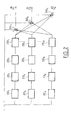
- Fig. 1 schematically represents a DS-CDMA system with K users.
- the data of a user k are spread in frequency by the corresponding signature in the module 100 k before being transmitted on a channel 110 k comprising P paths.
- the second characteristic mentioned above guarantees a low level of interference between two distinct users.
- the inter-correlation between two signatures is rarely zero. This is particularly the case in a so-called near-effect situation where a high power signal received from a user disturbs the reception of a low power signal from another user.
- the sum of the interference of the different users small if taken in isolation, can have very disruptive effects for detection.
- the received signal is filtered by a battery of suitable filters (200 1 , 200 2 , .., 200 K ), each suitable filter being relative to a given user.
- the estimated symbols are re-spread (220 k ) spectrally using the signature of the user in question before being filtered by a filter modeling the transmission channel (230 k ).
- a filter modeling the transmission channel 230 k .
- We thus have at the output of (230 k ) an estimate of the contributory part of the received signal attributable to user k.
- This purified signal can be directly detected after despreading or the elimination process can be iterated. Since the detection is of better quality at each iteration, we then obtain, over successive iterations, signals S k (i) which are better and better rid of multi-user interference.
- the serial elimination method is illustrated in Fig. 3: the signals received by the different users are first of all ordered in decreasing order of power, ie 1, .., K. We then proceed by successive eliminations of the contributory shares, starting with the strongest signal.
- the SIC detector has a series of cascaded stages, each eliminating interference due to a particular user. The first stage works on the antenna signal and each subsequent stage receives as input the output of the preceding stage. Each stage includes a suitable filter (300 k ), a detector (310 k ), a symbol re-spreading module (320 k ), a filter (330 k ) modeling the transmission channel k and a subtractor (340 k ) eliminating the contribution due to user k. Each stage also provides at the output of the detector (310 k ) a decision on the symbol received, S and k and the interference elimination process ends at the K th stage.
- ZF-DF Zero-Forcing Decision-Feedback
- the matrix processing has the effect of partially decorrelating the signals of the different users.
- the signals thus partially decorrelated are then subjected to a series elimination, after having been classified in decreasing order of amplitude, ie A 1 , .., A K.
- the detector comprises a plurality of stages, each stage i comprising a detector (410 i ) the output of which is multiplied by multipliers (415 i, i + 1 ), ..., (415 i, K ) for supplying products A i .F k, i with i ⁇ k, where F k, i is an element of the matrix F.
- each stage (k) we subtract (416 i, k ) the sum A i .F k, s and i where s and i is the estimated symbol for user i, i.e. the sum of the contributions of previous users i ⁇ k.
- the decision (410 k ) relating to the symbol transmitted by the user k is taken on the signal thus purified. By progressing from floor to floor, the estimated symbols s and k of the different users are obtained.
- Each iteration of the detection includes suitable filtering, channel formation and a combination of Rake type.
- the proposed method presupposes that the attenuation coefficients, phase rotations as well as the directions of arrival of all journeys of all users. This determination can be made by example by correlating pilot symbols issued by different users in suitable filters. However, this determination is often imprecise, which translates into by an imperfect or even erroneous elimination of multi-user interference.
- An object of the present invention is to propose a method and a device for detection that improves the elimination of multi-user interference in the presence multi-path channels.
- a subsidiary aim of the present invention is the determination simple and precise attenuation coefficients and phase rotations related to transmission paths of different users.
- the interference is eliminated by subtracting from the antenna signals the contributions of all the others users.
- the users are classified in order of received power and the interference is eliminated by subtracting the contributions of different users starting with more users strong powers received.
- said sequence comprises after the step of estimating said data, a deinterlacing step followed by a channel decoding and channel coding step and an interleaving step of said data.
- said sequence includes prior to the step of estimating the contribution of the user to the received signals, a step of spectral modulation and re-spreading at the means of the signature having served to spread spectrally the symbols of said user.
- the estimates of the signals transmitted from users being considered as a vector of estimates at K components where K is the number of users, said vector is subject to filtering cross-functional matrix before the decision stage.
- the estimated data and of users being considered as a vector of symbols at K components, said vector of symbols is subject to postcursor matrix filtering and the output of this filtering is subtracted, vector to vector, at the output of the filtering transverse matrix.
- the symbols from the modulation step being considered as a vector of symbols with K components
- said vector of symbols is subjected to a postcursor matrix filtering and the output of this filtering is subtracted, vector to vector, at the end of the transverse matrix filtering.
- the estimates of the signals transmitted by the different users are subjected to a matrix multiplication by a matrix (F T ) -1 before the step of estimating the data, where F T is the transpose of the lower triangular matrix F obtained by Cholesky decomposition of the signature correlation matrix used to spectrally spread the symbols of said users, the interference being eliminated, for a given user k, in a first phase, by subtracting from the k th component of the matrix product the sum A i . F k, i .
- a i is the amplitude of the signal transmitted by user i
- s and i is the symbol obtained by remodulation of the estimated data of user i and F k, i the (k, i) th element of the matrix F, the estimation of the data transmitted by the user k being carried out from the k th component after said subtraction and, in a second phase, by subtracting from the signals received by the different antennas, the sum of the contributions of all other users.
- the step of estimating the signal transmitted by the user, on the transmission channel ( k ), comprises forming channels in the directions of arrival of the different propagation paths ( p ) of said channel.
- channel formation for a propagation path of a transmission can place zeros in the directions of arrival of other routes of propagation of the same transmission channel.
- the channel formation (520 p, k ) for a propagation path ( p ) of a transmission channel ( k ) can still place zeros in the directions of arrival of all the propagation paths of the other transmission channels.
- the channel formation results are weighted (540 1, k , .., 540 p, k ) by complex coefficients and then summed, said coefficients being obtained from the estimated characteristics ( ⁇ and p, k , ⁇ and p, k ) of propagation of the different paths ( p ) of the transmission channel ( k ).
- the directions arrival and propagation characteristics of the different routes are estimated at starting from a priori knowledge of a symbol transmitted by said user.
- the detection method multi-user includes iteration of a set of sequences, each sequence of a user of the second iteration and of the following iterations operating on the game of antenna signals whose contributions from other users have been eliminated the previous iteration.
- the directions arrival and propagation characteristics of the different routes are estimated at starting from a priori knowledge of at least one pilot symbol transmitted by said user and, in subsequent iterations, this estimate is made from at least minus an estimate and remodulated data in a previous iteration in addition to said pilot symbol.
- the first iteration can operate without channel formation, in omni-directional, lane formation being applied from the second iteration.
- the invention is also defined by a multi-user detection device comprising means suitable for implementing the method set out above.
- the general idea underlying the invention is to get involved in a process of multi-user detection estimation of complex coefficients (including attenuation and phase rotation) and directions of arrival of the paths of spread.
- the interference rejection process benefits from better precision of the estimation of the respective contributions of the different users in the signal received.
- the process of estimating complex coefficients benefits from the rejection of multi-user interference by operating on signals purified.
- the device according to the invention uses a Rake type receiver illustrated in FIG. 5. Its particularity compared to a conventional Rake receiver is to integrate a beam formation according to the directions of arrival of the different paths.
- the device according to the invention comprises one receiver of this type per user, a single receiver (500 k ) being illustrated in FIG. 5.
- the various elements of the receiver (500 k ) are devoid of the index k.
- the receiver (500 k ) receives the outputs of the antennas 1, .., L from an antenna array, preferably linear and uniform although other types of array can also be envisaged, in particular circular arrays.
- ⁇ p, k ( t ) ⁇ p, k ( t ) + 2 ⁇ d ⁇ ( l- 1) cos ( ⁇ p, k ( t ))
- b k (t) is the symbol emitted by the user k
- n l, p, k ( t ) is the supposed white additive Gaussian noise at the antenna l for the path p of the user k, including thermal noise, multi-path interference and multi-user interference
- d is the lattice pitch
- ⁇ is the wavelength.
- the propagation along the path p of a user k is thus modeled by an attenuation coefficient ⁇ p, k ( t ) and a phase rotation v p, k ( t ).
- the total phase shift ⁇ l, p, k ( t ) results on the one hand from the phase rotation v p, k ( t ) induced on the path p and on the other hand from the path difference between the antenna l and the reference antenna 1 at the angle of arrival ⁇ p, k ( t ).
- the function of the estimator (530 p ) is to estimate on the one hand the attenuation coefficient ⁇ p, k and the phase rotation v p, k and on the other hand the angle of arrival ⁇ p, k .
- the estimator will preferably carry out a joint estimation of channel and direction of arrival according to the method set out in the French patent application entitled “Method of joint estimation of channel and direction of arrival” and filed the same day by the applicant. The content of this request is included here by reference.
- Said joint estimation method consists in looking for the values ⁇ p, k , ⁇ p, k and ⁇ p, k such that the quadratic distance D p, k is minimal.
- the estimation is carried out in three stages:
- Step 1 we estimate ⁇ l, p, k by minimizing the quadratic distance D l, p, k at each antenna:
- Step 2 we estimate ⁇ p, k and ⁇ p, k from a linear regression on the estimated values ⁇ and l, p, k ;
- Step 3 from the estimated values ⁇ and p , k and ⁇ and p , k we finally estimate ⁇ p, k by minimizing the quadratic distance This gives an estimated value ⁇ and p, k .
- each channel trainer (520 p ) also receives the estimated values ⁇ and p ', k supplied by the other estimators (530 p' ), p ' ⁇ p, of the paths p' of the same user. . This allows the channel trainer (520 p ) to place zeros in the reception diagram for the directions concerned ( ⁇ and p'k , p ' ⁇ p) so as to better separate the signals received from the different paths.
- each channel trainer (520 p ) of a user k receives the estimated values ⁇ and p ', k' (k ' ⁇ k) of all the directions of arrival of the other users so as to also be able to place zeros in these directions.
- the estimated values ⁇ and p, k and ⁇ and p, k are transmitted to a complex multiplier (540 p ) which multiplies the output signal of the channel trainer (530 p ) by the complex coefficient .
- the outputs of the P multipliers are then summed in a summator (550) to provide an output of the MRC (Maximum Ratio Combining) type.
- the operation performed by the receiver (500 k ) is then a suitable filtering. If instead of the summation, a simple maximum of the output values of the different branches is calculated, the expression of “adapted filtering” is no longer appropriate (it is no longer a filtering).
- the receiver (500 k ) a “Rake type” receiver whatever the type of processing at the output of the branches. In all cases, the output signal S k represents an estimate of the contribution of user k to the signal received by the network.
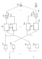
- Fig. 6 shows a multi-user detection device according to a first exemplary embodiment of the invention. Multi-user interference is eliminated in a parallel mode.
- the outputs of the antennas 1..L of the network are all connected to a battery of Rake type receivers (600 1 , .., 600 K ), the structure of which has been described in FIG. 5.
- the signals obtained at the output of the receivers are then subjected to a sequence of processing steps comprising: a flexible or hard decision step by means of the detectors (610 1 , .., 610 K ) providing in flexible or hard form the data transmitted by the different users, followed by a deinterlacing step (620 1 , ..., 620 K ) of the data thus obtained, a channel decoding / encoding step (630 1 , ..., 630 K ) and ( 640 1 , ..., 640 K ) providing a more reliable estimate of the data transmitted.
- this operation is carried out by means of decoding with flexible inputs and outputs (SISO for Soft Input Soft Output).
- SISO Soft Input Soft Output
- Re-encoding is not necessary if the data encoded at the decoding output is directly recovered.
- SOVA Soft Output Viterbi Algorithm
- the encoded data can be recovered directly along the maximum likelihood path.
- the data thus estimated are then again interleaved in (650 k ) before being remodulated and the symbols spectrally spread in (660 k ) by the signature of the user k.
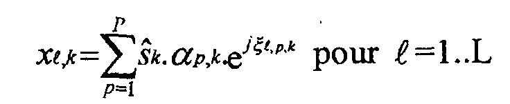
- each re-spread symbol s and k is then filtered by a filter (670 k ) modeling the transmission channel k and taking into account the geometry of the antenna array. More precisely, the filter (670 k ) calculates the following expressions: where ⁇ p, k and ⁇ l, p , k are the respective values of the attenuation coefficients and the phase shifts obtained by the joint estimation module of the receiver (600 k ).
- deinterlacing decoding / channel encoding, and interlacing are optional (the blocks (620 k , 630 k , 640 k , 650 k are then absent).
- Spectral re-spreading can be applied directly to the estimated symbol
- channel decoding with of course channel coding corresponding to the transmission makes it possible to lower the error rate and therefore to improve the reliability of the interference estimation and, by following, symbols transmitted.
- the first iteration can operate with an omni-directional antenna array diagram (that is to say without channel formation) in which case the calculation of ⁇ and p, k is not necessary.
- Fig. 7 illustrates a multi-user detection device according to a second exemplary embodiment of the invention.
- the elimination of the interference is here carried out in a series of K steps, K being the number of users.
- K being the number of users.
- the contributions of the different users in the received signals are ordered in decreasing order of power. For each user, for example, we will add the modules squared the outputs of adapted filters of the user connected to the different antennas and we will compare the are obtained.
- each stage comprises at the input a Rake type receiver (700 k ) as described in FIG. 5.
- the receiver on the first stage receives the L antenna signals and the receiver on a subsequent stage receives the L output signals on the previous stage.
- On leaving the receiver proceed as already described for FIG. 6 to a soft or hard decision (710 k ), deinterlacing (720 k ), channel decoding / re-encoding (730 k ) and (740 k ), interleaving (750 k ), remodulation and re-spreading (760 k ) estimated symbols then channel filtering (770 k ).
- the filters (770 k ) are identical to the filters (670 k ) already described.
- the L output signals of (770 k ) are then subtracted in (780 k ) from the L input signals of stage k to supply the L input signals of stage k + 1.
- the contributions of the various users are thus successively eliminated, starting with those which create the strongest interference.
- the outputs of the channel filters (770 k ) of the different stages 1..K can be used, like those of the channel filters (670 k ) of FIG. 6, in order to regenerate, for each user k, its contribution to the antenna signals, in the form of an L-tuple ( x l, k ).
- the contributions of the different users are subtracted one by one by the summers (780 k ) of the different floors.
- Fig. 8 represents a multi-user detection device according to a third embodiment of the invention.
- This embodiment uses the ZF-DF elimination principle described in the introduction.
- the outputs of the antennas 1..L are connected to a battery of K Rake type receivers having the structure described in FIG. 5.
- Each output line of the matrix multiplication comprises a series of modules (810 k ) to (870 k ) having the same functions as the corresponding modules (710 k ) to (770 k ).
- the module (860 k ) has been represented here in two parts, namely (861 k ) for the modulation function and (862 k ) for the spectral re-spreading function.
- the output signal of an interleaving module (850 k ) is subtracted from the respective inputs of the subsequent stages k ', k'> k in (807 k ', k ), after multiplication in (806 k', k ) by the coefficient A k. .F k, k ' .
- the choice of the output of (861 k ) and not the output of (810 k ) remodulated as in the conventional ZF-DF method allows advantage to be taken of channel decoding to refine the interference elimination on the next stage .
- each channel filter (870 k ) an L-tuplet ( x l, k ).
- the described process can be iterated.
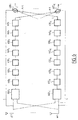
- Fig. 9a represents a multi-user detection device according to a fourth embodiment of the invention.
- This embodiment extends the parallel elimination mode in the sense that it now includes a “multi-equalization” function which we will explain below.
- the reference numbers indicated are the translates of those of FIG. 6 when they correspond to identical functions.
- the device shown in FIG. 9a nevertheless differs from that of FIG. 6 in that it comprises a linear filter (905) upstream of the decision modules (910 k ).
- the purpose of this filtering is to take into account the outputs of the Rake type receivers (900 k ) at different sampling times in eliminating the interference.
- the filter (905) is a transverse linear time filter which plays a role equivalent to that of a conventional transverse linear equalizer when a single user is considered.
- the filter (905) is a matrix filter which operates on vectors of size K and therefore uses matrices of size KxK instead of scalar coefficients, the number of such matrices corresponding to the number of time taps. of the filter.
- the diagonal coefficients of the different matrices allow the actual equalization while the coefficients outside the diagonals allow to take into account the temporal responses of the different channels in the rejection of the interference between users.
- the transversal filter (905) can be optimized by a technique known as that of forcing to zero (Zero Forcing or ZF) or minimizing the mean square error (Minimum Mean Square Error or MMSE).
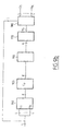
- Fig. 9b represents in an equivalent manner the device of FIG. 9a by highlighting the vector processing character of the different modules (900) to (980) each module respectively integrating the modules (900 1 , .., 900 K ), ... (980 1 , ..., 980 K ) of Fig. 9a (for example, the module (900) is a battery of Rake type receivers).
- the matrix filter (905) remains of course unchanged.
- Fig. 10 shows a multi-user detection device according to a fifth embodiment of the invention.
- Modules (1000), (1010), ... (1080) are modules identical to modules (900), (910), ..., (980) of FIG. 9, each module operating, as we said, on a vector at K components.
- the module (1060) has been represented here in two parts (1061) and (1062) to separate the modulation function (1061) from that of spectral spreading (1062).
- the device comprises a transverse precursor filter (1005) identical to the filter (905) and a postcursor filter (1007) filtering the re-interlaced and re-modulated output of the module (1061). The output of the postcursor filter is subtracted (1006) from the input of the decision (1010).
- the assembly constituted by the transverse filter (1005) and the filter feedback (1007) can also be optimized using a known technique, ZF or MMSE for example.
- this embodiment can be seen as a generalization of the ZF-DF mode exposed in FIG. 8.
- the postcursor filter (1007) should be causal to ensure that there is no not to subtract the contribution of time samples not yet available in the time of subtraction from the current sample. This may in particular impose constraints on the length of the interlacing.
- the postcursor filter (1007) will filter the output of the re-modulated decision module (1010) which will allow relax the causality constraint at the cost, however, of giving up the benefit of the channel decoding in the evaluation of inter-symbol interference by the filter postcursor.
- FIG. 9 and 10 both use "multi-equalization" derived from symbol-by-symbol single user equalization. It is however clear to those skilled in the art that the invention is also capable of generalization to the family of equalization techniques with estimation of sequences of symbols, namely MLSE (Maximum Likelihood Sequence Estimation), DDFSE (Delayed Decision Feedback Sequence Estimation), RSSE (Reduced State Sequence Estimate) etc. All these techniques can also be transposed by means of the invention in the multi-user situation.
- MLSE Maximum Likelihood Sequence Estimation
- DDFSE Delayed Decision Feedback Sequence Estimation
- RSSE Reduced State Sequence Estimate
Landscapes
- Engineering & Computer Science (AREA)
- Computer Networks & Wireless Communication (AREA)
- Signal Processing (AREA)
- Mobile Radio Communication Systems (AREA)
- Radio Transmission System (AREA)
- Noise Elimination (AREA)
Abstract
Description




Claims (18)
- Méthode de détection multi-utilisateur avec élimination d'interférence entre utilisateurs, chaque utilisateur transmettant des données modulées sous forme de symboles sur un canal de transmission, chaque canal de transmission (k) comprenant au moins un trajet de propagation (p) et chaque trajet de propagation arrivant sur un réseau d'antennes (ℓ) de réception selon une direction d'arrivée p,k , la méthode comprenant au moins une séquence d'étapes pour chaque utilisateur, caractérisée en ce que chaque séquence comprend :(a) une étape d'estimation du signal transmis (500k,600k,700k,800k,900k,900,1000) par l'utilisateur à partir des signaux d'antennes, ladite étape effectuant une estimation (530p) de la direction d'arrivée ( p,k ) et de caractéristiques (α p,k ,ν p,k ) de propagation de chaque trajet (p) du canal de transmission (k) à partir desdits signaux ;(b) une étape d'estimation des données transmises (610k,710k,810k,910k,910,1010) par l'utilisateur à partir de ladite estimation du signal transmis ;(c) une étape d'estimation de la contribution (670k,770k,870k,970k,970,1070) de l'utilisateur aux signaux reçus par les différentes antennes à partir des données estimées à l'étape (b) et de la direction d'arrivée ainsi que les caractéristiques de propagation estimées à l'étape (a) ;(d) une étape d'élimination d'interférence (680k',780k,880k',980k',980,1080) soustrayant aux signaux d'antennes la contribution estimée à l'étape (c) pour obtenir des signaux d'antennes épurés ;les signaux d'antennes épurés fournis par au moins une première séquence étant utilisés comme signaux d'antennes par au moins une seconde séquence.
- Méthode de détection multi-utilisateur selon la revendication 1, caractérisée en ce que, pour un utilisateur donné k, l'interférence est éliminée en soustrayant (680k,880k) aux signaux d'antennes les contributions de tous les autres utilisateurs.
- Méthode de détection multi-utilisateur selon la revendication 1, caractérisée en ce que les utilisateurs sont classés par ordre de puissance reçue et que l'interférence est éliminée en soustrayant (780k) l'une après l'autre les contributions des différents utilisateurs en commençant par les utilisateurs de plus fortes puissances reçues.
- Méthode de détection multi-utilisateur selon l'une des revendications précédentes, caractérisée en ce que, pour chaque utilisateur k, ladite séquence comprend après l'étape d'estimation desdites données (61 0k,710k,810k,910k,910,1010), une étape de désentrelacement (620k,720k,820k,920k,920,1020) suivie d'une étape de décodage canal (630k,730k,830k,930k,930,1030), de codage canal (640k,740k,840k,940k,940,1040) et d'une étape d'entrelacement (650k,750k,850k,950k,950,1050) desdites données.
- Méthode de détection multi-utilisateur selon l'une des revendications précédentes, caractérisée en ce que, pour chaque utilisateur k, ladite séquence comprend préalablement à l'étape d'estimation de la contribution (670k,770k,870k,970k,970,1070) de l'utilisateur aux signaux reçus, une étape de modulation et de réétalement spectral (660k,760k,860k,960k,960,1060) au moyen de la signature ayant servi à étaler spectralement les symboles dudit utilisateur.
- Méthode de détection multi-utilisateur selon l'une des revendications précédentes, caractérisée en ce que, les estimations des signaux transmis des utilisateurs étant considérées comme un vecteur d'estimations à K composantes où K est le nombre d'utilisateurs, ledit vecteur est soumis à un filtrage matriciel transverse (905,1005) avant l'étape de décision (910,1010).
- Méthode de détection multi-utilisateur selon la revendication 6, caractérisée en ce que, les données estimées et remodulées des utilisateurs étant considérés comme un vecteur de symboles à K composantes, ledit vecteur de symboles est soumis à un filtrage matriciel postcurseur (1007) et la sortie de ce filtrage est soustraite, vecteur à vecteur, à la sortie du filtrage matriciel transverse (1005).
- Méthode de détection multi-utilisateur selon les revendications 4, 5 et 6, caractérisée en ce que, les symboles issus de l'étape de modulation (1061) étant considérés comme un vecteur de symboles à K composantes, ledit vecteur de symboles est soumis à un filtrage matriciel postcurseur (1007) et la sortie de ce filtrage est soustraite, vecteur à vecteur, à la sortie du filtrage matriciel transverse (1005).
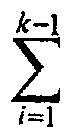
- Méthode de détection multi-utilisateur selon les revendications 2 et 4, caractérisée en ce que les estimations des signaux transmis par les différents utilisateurs sont soumis à une multiplication matricielle (805) par une matrice (FT)-1 avant l'étape d'estimation des données, où FT est la transposée de la matrice triangulaire inférieure F obtenue par décomposition de Cholesky de la matrice de corrélation des signatures ayant servi à étaler spectralement les symboles desdits utilisateurs, l'interférence étant éliminée, pour un utilisateur k donné, dans une première phase, en soustrayant (807k',k) de la kième composante du produit matriciel la sommeAi.Fk,i .s andi où Ai est l'amplitude du signal transmis par l'utilisateur i, s andi est le symbole obtenu par remodulation (861k) des données estimées de l'utilisateur i et Fk,i le (k,i) ième élément de la matrice F, l'estimation des données transmises par l'utilisateur k étant effectuée à partir de la kième composante après ladite soustraction et, dans une seconde phase, en soustrayant (880k) aux signaux reçus par les différentes antennes, la somme des contributions de tous les autres utilisateurs.
- Méthode de détection multi-utilisateur selon l'une des revendications précédentes, caractérisée en ce que, pour chaque utilisateur k, l'étape d'estimation du signal transmis par l'utilisateur, sur le canal de transmission (k), comprend une formation de voies (5201,..,520P) dans les directions d'arrivée des différents trajets de propagation (p) dudit canal.
- Méthode de détection multi-utilisateur selon la revendication 10, caractérisée en ce que la formation de voie (520p) pour un trajet de propagation d'un canal de transmission place des zéros dans les directions d'arrivée des autres trajets de propagation du même canal de transmission.
- Méthode de détection multi-utilisateur selon la revendication 11, caractérisée en ce que la formation de voie (520p,k) pour un trajet de propagation (p) d'un canal de transmission (k) place des zéros dans les directions d'arrivée de tous les trajets de propagation des autres canaux de transmission.
- Méthode de détection multi-utilisateur selon l'une des revendications 10 à 12, caractérisée en ce que, pour chaque canal de transmission (k), les résultats de formation de voies sont pondérés (5401,k,..,540P,k) par des coefficients complexes puis sommés, lesdits coefficients étant obtenus à partir des caractéristiques estimées (α and p,k ,ν and p,k ) de propagation des différents trajets (p) du canal de transmission (k).
- Méthode de détection multi-utilisateur selon l'une des revendications précédentes, caractérisée en ce que, pour chaque utilisateur k, les directions d'arrivée et les caractéristiques de propagation des différents trajets sont estimées à partir de la connaissance a priori d'un symbole transmis par ledit utilisateur.
- Méthode de détection multi-utilisateur selon la revendication 2 ou bien 4 à 14 en dépendance avec 2, caractérisée en ce qu'elle comprend l'itération d'un ensemble de séquences, chaque séquence d'un utilisateur de la seconde itération et des itérations suivantes opérant sur le jeu de signaux d'antennes dont les contributions des autres utilisateurs ont été éliminées à l'itération précédente.
- Méthode de détection multi-utilisateur selon la revendication 15, caractérisée en ce que, à la première itération, pour chaque utilisateur, les directions d'arrivée et les caractéristiques de propagation des différents trajets sont estimées à partir de la connaissance a priori d'au moins un symbole pilote transmis par ledit utilisateur et qu'aux itérations ultérieures cette estimation est effectuée à partir d'au moins une donnée estimée et remodulée à une itération précédente en sus dudit symbole pilote
- Méthode de détection multi-utilisateur selon les revendications 10 et 15, caractérisée en ce que, les caractéristiques de propagation des différents trajets étant connues a priori, la première itération opère sans formation de voies, en mode omni-directionnel, la formation de voies étant appliquée dès la seconde itération.
- Dispositif de détection multi-utilisateur caractérisé en ce qu'il comprend des moyens adaptés à mettre en oeuvre la méthode selon l'une des revendications précédentes.
Applications Claiming Priority (2)
| Application Number | Priority Date | Filing Date | Title |
|---|---|---|---|
| FR0011250A FR2813464B1 (fr) | 2000-08-29 | 2000-08-29 | Methode de detection multi-utilisateur |
| FR0011250 | 2000-08-29 |
Publications (1)
| Publication Number | Publication Date |
|---|---|
| EP1184997A1 true EP1184997A1 (fr) | 2002-03-06 |
Family
ID=8853947
Family Applications (1)
| Application Number | Title | Priority Date | Filing Date |
|---|---|---|---|
| EP01402235A Ceased EP1184997A1 (fr) | 2000-08-29 | 2001-08-27 | Méthode de détection multi-utilisateur |
Country Status (4)
| Country | Link |
|---|---|
| US (1) | US7079607B2 (fr) |
| EP (1) | EP1184997A1 (fr) |
| JP (1) | JP2002111563A (fr) |
| FR (1) | FR2813464B1 (fr) |
Families Citing this family (18)
| Publication number | Priority date | Publication date | Assignee | Title |
|---|---|---|---|---|
| FR2829326A1 (fr) * | 2001-09-06 | 2003-03-07 | France Telecom | Procede et systeme de reception iterative sous optimale pour systeme de transmission haut debit cdma |
| GB2380371A (en) * | 2001-10-01 | 2003-04-02 | Ipwireless Inc | Method and arrangement for use in a single user detector for a CDMA multi-path system using a finite impulse response filter |
| FR2838582B1 (fr) * | 2002-04-12 | 2004-05-21 | Commissariat Energie Atomique | Procede et dispositif de detection de donnees transmises par etalement de spectre |
| GB2403104B (en) * | 2003-06-16 | 2006-06-14 | Inmarsat Ltd | Communication method and apparatus |
| JP4182345B2 (ja) * | 2003-06-26 | 2008-11-19 | 日本電気株式会社 | 干渉キャンセルユニット及びマルチユーザ干渉キャンセラ |
| US7469025B2 (en) * | 2003-09-08 | 2008-12-23 | Aktino, Inc. | Decision feedback transceiver for multichannel communication system |
| WO2005034406A2 (fr) * | 2003-09-25 | 2005-04-14 | Interdigital Technology Corporation | Procede et systeme destines a ameliorer la reception de signaux de communication sans fil |
| GB2411546B (en) * | 2004-02-27 | 2007-05-30 | Toshiba Res Europ Ltd | Channel Estimation in a CDMA Receiver |
| BRPI0514916A (pt) * | 2005-01-05 | 2008-06-24 | Atc Tech Llc | método de comunicação, sistema, detector redutor de interferência para um sistema de comunicação de satélite, portal para um sistema de terminal sem fios de satélite, redutor de interferência, transmissor para um componente, radioterminal, e, método de reduzir interferência |
| US20060171412A1 (en) * | 2005-01-13 | 2006-08-03 | Emmanuel Kanterakis | Non-linear reception method and apparatus |
| US7929593B2 (en) * | 2008-04-15 | 2011-04-19 | Telefonaktiebolaget Lm Ericsson (Publ) | Method and apparatus for successive interference subtraction with covariance root processing |
| KR101552266B1 (ko) * | 2009-04-07 | 2015-09-11 | 삼성전자주식회사 | 수신기, 그의 간섭 제거 방법 및 그를 위한 송신기 |
| CN101945073B (zh) * | 2009-07-03 | 2013-02-27 | 中兴通讯股份有限公司 | 基于导频的时偏估计装置和方法 |
| US20110195658A1 (en) * | 2010-02-11 | 2011-08-11 | Electronics And Telecommunications Research Institute | Layered retransmission apparatus and method, reception apparatus and reception method |
| US8824590B2 (en) * | 2010-02-11 | 2014-09-02 | Electronics And Telecommunications Research Institute | Layered transmission apparatus and method, reception apparatus and reception method |
| US8687740B2 (en) * | 2010-02-11 | 2014-04-01 | Electronics And Telecommunications Research Institute | Receiver and reception method for layered modulation |
| US20110194645A1 (en) * | 2010-02-11 | 2011-08-11 | Electronics And Telecommunications Research Institute | Layered transmission apparatus and method, reception apparatus, and reception method |
| US11677423B1 (en) | 2021-07-23 | 2023-06-13 | T-Mobile Usa, Inc. | Interference mitigation in wireless communication using artificial interference signal |
Citations (1)
| Publication number | Priority date | Publication date | Assignee | Title |
|---|---|---|---|---|
| EP0978951A2 (fr) * | 1998-08-04 | 2000-02-09 | Lucent Technologies Inc. | Détecteur à utilisateurs multiples spatio-temporel linéaire |
-
2000
- 2000-08-29 FR FR0011250A patent/FR2813464B1/fr not_active Expired - Fee Related
-
2001
- 2001-08-01 US US09/918,477 patent/US7079607B2/en not_active Expired - Fee Related
- 2001-08-02 JP JP2001234944A patent/JP2002111563A/ja not_active Withdrawn
- 2001-08-27 EP EP01402235A patent/EP1184997A1/fr not_active Ceased
Patent Citations (1)
| Publication number | Priority date | Publication date | Assignee | Title |
|---|---|---|---|---|
| EP0978951A2 (fr) * | 1998-08-04 | 2000-02-09 | Lucent Technologies Inc. | Détecteur à utilisateurs multiples spatio-temporel linéaire |
Non-Patent Citations (3)
| Title |
|---|
| KHALAJ B H ET AL: "Spatio-temporal channel estimation techniques for multiple access spread spectrum systems with antenna arrays", ICC 95 SEATTLE. COMMUNICATIONS - GATEWAY TO GLOBALIZATION. 1995 IEEE INTERNATIONAL CONFERENCE ON COMMUNICATIONS (CAT. NO.95CH35749), PROCEEDINGS IEEE INTERNATIONAL CONFERENCE ON COMMUNICATIONS ICC 95, SEATTLE, WA, USA, 18-22 JUNE 1995, 1995, New York, NY, USA, IEEE, USA, pages 1520 - 1524 vol.3, XP002168234, ISBN: 0-7803-2486-2 * |
| MOSHAVI S: "MULTI-USER DETECTION FOR DS-CDMA COMMUNICATIONS", IEEE COMMUNICATIONS MAGAZINE,US,IEEE SERVICE CENTER. PISCATAWAY, N.J, vol. 34, no. 10, 1 October 1996 (1996-10-01), pages 124 - 136, XP000694489, ISSN: 0163-6804 * |
| REED M C ET AL: "ITERATIVE MULTIUSER DETECTION USING ANTENNA ARRAYS AND FEC ON MULTIPATH CHANNELS", IEEE JOURNAL ON SELECTED AREAS IN COMMUNICATIONS,IEEE INC. NEW YORK,US, vol. 17, no. 12, December 1999 (1999-12-01), pages 2082 - 2089, XP000920304, ISSN: 0733-8716 * |
Also Published As
| Publication number | Publication date |
|---|---|
| US7079607B2 (en) | 2006-07-18 |
| FR2813464B1 (fr) | 2006-07-07 |
| US20020041644A1 (en) | 2002-04-11 |
| JP2002111563A (ja) | 2002-04-12 |
| FR2813464A1 (fr) | 2002-03-01 |
Similar Documents
| Publication | Publication Date | Title |
|---|---|---|
| EP1189361B1 (fr) | Méthode de détection multi-utilisateur | |
| FR2813464A1 (fr) | Methode de detection multi-utilisateur | |
| FR2715523A1 (fr) | Récepteur et procédé de réception pour un système d'accès multiple par répartition par code. | |
| FR2714243A1 (fr) | Procédé et récepteur pour démoduler au moins un signal AMRC à partir d'un signal reçu. | |
| FR2774831A1 (fr) | Recepteur adaptatif de signaux pour systeme de communications a acces pultiples par repartition a codes | |
| WO2002023841A1 (fr) | Procede d'estimation optimale d'un canal de propagation reposant uniquement sur les symboles pilotes et estimateur correspondant | |
| FR2742619A1 (fr) | Procede d'egalisation multicapteur permettant une reception multicapteur en presence d'interferences et de multitrajets de propagation, et recepteur pour sa mise en oeuvre | |
| FR2810820A1 (fr) | Procede et dispositif de reception d'un signal radio | |
| FR2813465A1 (fr) | Methode d'estimation conjointe de canal et de direction d'arrivee | |
| EP3343784A1 (fr) | Procede de lutte anti-interferences par filtrage spatial ou filtrage spatio-temporel dans un recepteur multi-voies | |
| EP1187366B1 (fr) | Récepteur CDMA adaptif uni-modulaire | |
| EP0669729B1 (fr) | Procédé permettant une égalisation multivoie dans un récepteur radioélectrique, en présence d'interférences et de multitrajets de propagation | |
| EP0820157B1 (fr) | Procédé de démodulation différentielle numérique | |
| EP1105975B1 (fr) | Recepteur en rateau iteratif et procede de reception correspondant | |
| EP1221773A1 (fr) | Méthode et dispositif de détection multi-utilisateur en mode DS-CDMA | |
| EP1221206B1 (fr) | Procede et dispositif pour demoduler des signaux provenant de multi-utilisateurs | |
| FR2813728A1 (fr) | Recepteur cdma adaptatif bi-modulaire | |
| EP1413066B1 (fr) | Dispositif de detection conjointe de codes cdma pour liaison descendante a trajets multiples | |
| EP1135855A1 (fr) | Filtre numerique a architecture parallele et recepteur de signaux a etalement de spectre utilisant un tel filtre | |
| WO2007028917A2 (fr) | Estimation iterative de canal de mimo dans un reseau cdma | |
| WO2005027367A1 (fr) | Procede de reception d’un signal cdma a annulation d’interference et recepteur correspondant | |
| EP1826916B1 (fr) | Procédé et dispositif de détection de données transmises par étalement de spectre | |
| WO2005109708A1 (fr) | Procede de determination de codes d’etalement utilises dans un signal cdma et dispositif de communication correspondant. | |
| WO2006131665A1 (fr) | Dispositif et procede de selection d'un recepteur en fonction de l'environnement |
Legal Events
| Date | Code | Title | Description |
|---|---|---|---|
| PUAI | Public reference made under article 153(3) epc to a published international application that has entered the european phase |
Free format text: ORIGINAL CODE: 0009012 |
|
| AK | Designated contracting states |
Kind code of ref document: A1 Designated state(s): AT BE CH CY DE DK ES FI FR GB GR IE IT LI LU MC NL PT SE TR |
|
| AX | Request for extension of the european patent |
Free format text: AL;LT;LV;MK;RO;SI |
|
| 17P | Request for examination filed |
Effective date: 20020613 |
|
| AKX | Designation fees paid |
Free format text: AT BE CH CY DE DK ES FI FR GB GR IE IT LI LU MC NL PT SE TR |
|
| RAP1 | Party data changed (applicant data changed or rights of an application transferred) |
Owner name: MITSUBISHI ELECTRIC INFORMATION TECHNOLOGY CENTRE |
|
| 17Q | First examination report despatched |
Effective date: 20060712 |
|
| RAP1 | Party data changed (applicant data changed or rights of an application transferred) |
Owner name: MITSUBISHI ELECTRIC R&D CENTRE EUROPE B.V. |
|
| STAA | Information on the status of an ep patent application or granted ep patent |
Free format text: STATUS: THE APPLICATION HAS BEEN REFUSED |
|
| 18R | Application refused |
Effective date: 20090914 |