EP1184943A1 - Chalcogenide glass based raman optical amplifier - Google Patents
Chalcogenide glass based raman optical amplifier Download PDFInfo
- Publication number
- EP1184943A1 EP1184943A1 EP01302211A EP01302211A EP1184943A1 EP 1184943 A1 EP1184943 A1 EP 1184943A1 EP 01302211 A EP01302211 A EP 01302211A EP 01302211 A EP01302211 A EP 01302211A EP 1184943 A1 EP1184943 A1 EP 1184943A1
- Authority
- EP
- European Patent Office
- Prior art keywords
- optical
- pump
- light
- chalcogenide glass
- optical waveguide
- Prior art date
- Legal status (The legal status is an assumption and is not a legal conclusion. Google has not performed a legal analysis and makes no representation as to the accuracy of the status listed.)
- Granted
Links
- 230000003287 optical effect Effects 0.000 title claims abstract description 71
- 239000005387 chalcogenide glass Substances 0.000 title claims abstract description 60
- 238000001069 Raman spectroscopy Methods 0.000 title claims description 61
- VYPSYNLAJGMNEJ-UHFFFAOYSA-N Silicium dioxide Chemical compound O=[Si]=O VYPSYNLAJGMNEJ-UHFFFAOYSA-N 0.000 claims description 32
- 230000003321 amplification Effects 0.000 claims description 25
- 238000003199 nucleic acid amplification method Methods 0.000 claims description 25
- 238000000034 method Methods 0.000 claims description 23
- 239000013307 optical fiber Substances 0.000 claims description 11
- 239000000377 silicon dioxide Substances 0.000 claims description 11
- 150000004770 chalcogenides Chemical class 0.000 claims description 6
- 238000004891 communication Methods 0.000 claims description 5
- 230000004044 response Effects 0.000 claims description 5
- 230000008878 coupling Effects 0.000 claims 2
- 238000010168 coupling process Methods 0.000 claims 2
- 238000005859 coupling reaction Methods 0.000 claims 2
- 239000000835 fiber Substances 0.000 description 40
- 238000005253 cladding Methods 0.000 description 22
- 239000011521 glass Substances 0.000 description 22
- 230000008569 process Effects 0.000 description 14
- 239000011669 selenium Substances 0.000 description 14
- 230000005540 biological transmission Effects 0.000 description 10
- 239000000203 mixture Substances 0.000 description 10
- 239000007789 gas Substances 0.000 description 9
- 229910052761 rare earth metal Inorganic materials 0.000 description 8
- 150000002910 rare earth metals Chemical class 0.000 description 6
- 239000000155 melt Substances 0.000 description 5
- BASFCYQUMIYNBI-UHFFFAOYSA-N platinum Chemical compound [Pt] BASFCYQUMIYNBI-UHFFFAOYSA-N 0.000 description 4
- 150000001875 compounds Chemical class 0.000 description 3
- 229910052751 metal Inorganic materials 0.000 description 3
- 239000002184 metal Substances 0.000 description 3
- -1 100x Chemical compound 0.000 description 2
- IJGRMHOSHXDMSA-UHFFFAOYSA-N Atomic nitrogen Chemical compound N#N IJGRMHOSHXDMSA-UHFFFAOYSA-N 0.000 description 2
- 229910052691 Erbium Inorganic materials 0.000 description 2
- NINIDFKCEFEMDL-UHFFFAOYSA-N Sulfur Chemical compound [S] NINIDFKCEFEMDL-UHFFFAOYSA-N 0.000 description 2
- 238000010521 absorption reaction Methods 0.000 description 2
- 239000000460 chlorine Substances 0.000 description 2
- UYAHIZSMUZPPFV-UHFFFAOYSA-N erbium Chemical compound [Er] UYAHIZSMUZPPFV-UHFFFAOYSA-N 0.000 description 2
- 239000000156 glass melt Substances 0.000 description 2
- 239000000463 material Substances 0.000 description 2
- 238000002844 melting Methods 0.000 description 2
- 230000008018 melting Effects 0.000 description 2
- 239000000075 oxide glass Substances 0.000 description 2
- 229910052697 platinum Inorganic materials 0.000 description 2
- 230000001902 propagating effect Effects 0.000 description 2
- 238000005086 pumping Methods 0.000 description 2
- 230000001105 regulatory effect Effects 0.000 description 2
- 229910052711 selenium Inorganic materials 0.000 description 2
- 229910052717 sulfur Inorganic materials 0.000 description 2
- 239000011593 sulfur Substances 0.000 description 2
- 229910052714 tellurium Inorganic materials 0.000 description 2
- 230000007704 transition Effects 0.000 description 2
- ZCYVEMRRCGMTRW-UHFFFAOYSA-N 7553-56-2 Chemical compound [I] ZCYVEMRRCGMTRW-UHFFFAOYSA-N 0.000 description 1
- WKBOTKDWSSQWDR-UHFFFAOYSA-N Bromine atom Chemical compound [Br] WKBOTKDWSSQWDR-UHFFFAOYSA-N 0.000 description 1
- ZAMOUSCENKQFHK-UHFFFAOYSA-N Chlorine atom Chemical compound [Cl] ZAMOUSCENKQFHK-UHFFFAOYSA-N 0.000 description 1
- GYHNNYVSQQEPJS-UHFFFAOYSA-N Gallium Chemical compound [Ga] GYHNNYVSQQEPJS-UHFFFAOYSA-N 0.000 description 1
- 229910001260 Pt alloy Inorganic materials 0.000 description 1
- BUGBHKTXTAQXES-UHFFFAOYSA-N Selenium Chemical compound [Se] BUGBHKTXTAQXES-UHFFFAOYSA-N 0.000 description 1
- XUIMIQQOPSSXEZ-UHFFFAOYSA-N Silicon Chemical compound [Si] XUIMIQQOPSSXEZ-UHFFFAOYSA-N 0.000 description 1
- ATJFFYVFTNAWJD-UHFFFAOYSA-N Tin Chemical compound [Sn] ATJFFYVFTNAWJD-UHFFFAOYSA-N 0.000 description 1
- 229910052769 Ytterbium Inorganic materials 0.000 description 1
- 229910045601 alloy Inorganic materials 0.000 description 1
- 239000000956 alloy Substances 0.000 description 1
- 229910052785 arsenic Inorganic materials 0.000 description 1
- RQNWIZPPADIBDY-UHFFFAOYSA-N arsenic atom Chemical compound [As] RQNWIZPPADIBDY-UHFFFAOYSA-N 0.000 description 1
- GDTBXPJZTBHREO-UHFFFAOYSA-N bromine Substances BrBr GDTBXPJZTBHREO-UHFFFAOYSA-N 0.000 description 1
- 229910052794 bromium Inorganic materials 0.000 description 1
- 229910052801 chlorine Inorganic materials 0.000 description 1
- 238000010276 construction Methods 0.000 description 1
- 230000000694 effects Effects 0.000 description 1
- 238000012681 fiber drawing Methods 0.000 description 1
- 229910052733 gallium Inorganic materials 0.000 description 1
- 229910052732 germanium Inorganic materials 0.000 description 1
- GNPVGFCGXDBREM-UHFFFAOYSA-N germanium atom Chemical compound [Ge] GNPVGFCGXDBREM-UHFFFAOYSA-N 0.000 description 1
- 239000003365 glass fiber Substances 0.000 description 1
- 230000005484 gravity Effects 0.000 description 1
- 229910052734 helium Inorganic materials 0.000 description 1
- 239000001307 helium Substances 0.000 description 1
- SWQJXJOGLNCZEY-UHFFFAOYSA-N helium atom Chemical compound [He] SWQJXJOGLNCZEY-UHFFFAOYSA-N 0.000 description 1
- BHEPBYXIRTUNPN-UHFFFAOYSA-N hydridophosphorus(.) (triplet) Chemical compound [PH] BHEPBYXIRTUNPN-UHFFFAOYSA-N 0.000 description 1
- 230000006872 improvement Effects 0.000 description 1
- 229910001026 inconel Inorganic materials 0.000 description 1
- 229910052738 indium Inorganic materials 0.000 description 1
- APFVFJFRJDLVQX-UHFFFAOYSA-N indium atom Chemical compound [In] APFVFJFRJDLVQX-UHFFFAOYSA-N 0.000 description 1
- 239000011261 inert gas Substances 0.000 description 1
- 229910052740 iodine Inorganic materials 0.000 description 1
- 239000011630 iodine Substances 0.000 description 1
- 238000004519 manufacturing process Methods 0.000 description 1
- 229910052757 nitrogen Inorganic materials 0.000 description 1
- 239000005304 optical glass Substances 0.000 description 1
- 229910052958 orpiment Inorganic materials 0.000 description 1
- 230000037361 pathway Effects 0.000 description 1
- 239000010453 quartz Substances 0.000 description 1
- 229910052710 silicon Inorganic materials 0.000 description 1
- 239000010703 silicon Substances 0.000 description 1
- 230000003595 spectral effect Effects 0.000 description 1
- 238000001228 spectrum Methods 0.000 description 1
- 239000000126 substance Substances 0.000 description 1
- PORWMNRCUJJQNO-UHFFFAOYSA-N tellurium atom Chemical compound [Te] PORWMNRCUJJQNO-UHFFFAOYSA-N 0.000 description 1
- 229910052716 thallium Inorganic materials 0.000 description 1
- BKVIYDNLLOSFOA-UHFFFAOYSA-N thallium Chemical compound [Tl] BKVIYDNLLOSFOA-UHFFFAOYSA-N 0.000 description 1
- XLYOFNOQVPJJNP-UHFFFAOYSA-N water Substances O XLYOFNOQVPJJNP-UHFFFAOYSA-N 0.000 description 1
- NAWDYIZEMPQZHO-UHFFFAOYSA-N ytterbium Chemical compound [Yb] NAWDYIZEMPQZHO-UHFFFAOYSA-N 0.000 description 1
Images

Classifications
-
- H—ELECTRICITY
- H01—ELECTRIC ELEMENTS
- H01S—DEVICES USING THE PROCESS OF LIGHT AMPLIFICATION BY STIMULATED EMISSION OF RADIATION [LASER] TO AMPLIFY OR GENERATE LIGHT; DEVICES USING STIMULATED EMISSION OF ELECTROMAGNETIC RADIATION IN WAVE RANGES OTHER THAN OPTICAL
- H01S3/00—Lasers, i.e. devices using stimulated emission of electromagnetic radiation in the infrared, visible or ultraviolet wave range
- H01S3/30—Lasers, i.e. devices using stimulated emission of electromagnetic radiation in the infrared, visible or ultraviolet wave range using scattering effects, e.g. stimulated Brillouin or Raman effects
- H01S3/302—Lasers, i.e. devices using stimulated emission of electromagnetic radiation in the infrared, visible or ultraviolet wave range using scattering effects, e.g. stimulated Brillouin or Raman effects in an optical fibre
-
- H—ELECTRICITY
- H01—ELECTRIC ELEMENTS
- H01S—DEVICES USING THE PROCESS OF LIGHT AMPLIFICATION BY STIMULATED EMISSION OF RADIATION [LASER] TO AMPLIFY OR GENERATE LIGHT; DEVICES USING STIMULATED EMISSION OF ELECTROMAGNETIC RADIATION IN WAVE RANGES OTHER THAN OPTICAL
- H01S3/00—Lasers, i.e. devices using stimulated emission of electromagnetic radiation in the infrared, visible or ultraviolet wave range
- H01S3/09—Processes or apparatus for excitation, e.g. pumping
- H01S3/091—Processes or apparatus for excitation, e.g. pumping using optical pumping
- H01S3/094—Processes or apparatus for excitation, e.g. pumping using optical pumping by coherent light
- H01S3/094003—Processes or apparatus for excitation, e.g. pumping using optical pumping by coherent light the pumped medium being a fibre
-
- H—ELECTRICITY
- H01—ELECTRIC ELEMENTS
- H01S—DEVICES USING THE PROCESS OF LIGHT AMPLIFICATION BY STIMULATED EMISSION OF RADIATION [LASER] TO AMPLIFY OR GENERATE LIGHT; DEVICES USING STIMULATED EMISSION OF ELECTROMAGNETIC RADIATION IN WAVE RANGES OTHER THAN OPTICAL
- H01S3/00—Lasers, i.e. devices using stimulated emission of electromagnetic radiation in the infrared, visible or ultraviolet wave range
- H01S3/14—Lasers, i.e. devices using stimulated emission of electromagnetic radiation in the infrared, visible or ultraviolet wave range characterised by the material used as the active medium
- H01S3/16—Solid materials
- H01S3/17—Solid materials amorphous, e.g. glass
- H01S3/171—Solid materials amorphous, e.g. glass chalcogenide glass
Definitions
- This invention relates to Raman optical amplifiers.
- optical communication systems often provide for amplification of optical signals at regular intervals along optical transmission fibers.
- the amplification may be produced by amplifiers based on rare-earth elements such as erbium and ytterbium or by amplifiers based on the Raman effect.
- Rare-earth amplifiers have limited bandwidth due to their reliance on selected atomic level transitions. Amplification occurs at discrete wavelengths that correspond to the selected atomic transitions.
- Broadband erbium doped fiber amplifiers are somewhat improved rare earth amplifiers so that these rare-earth amplifiers can power some wavelength division multiplexed (WDM) optical networks.
- WDM wavelength division multiplexed
- Raman amplifiers are naturally tunable and capable of providing amplification at wavelengths in a broad optical band.
- an amplification wavelength is simply selected by tuning a pump laser to produce a wavelength capable of producing stimulated Raman emission at the selected wavelength.
- Raman amplifiers can cover a much wider spectral range than rare-earth based amplifiers. Furthermore, Raman amplifiers have effectively lower noise levels than rare-earth amplifiers. These advantages make Raman amplifiers desirable for long haul WDM systems where the transmission bandwidth may be broad.
- conventional Raman fiber amplifiers provide relatively low gain.
- an optical signal often has to propagate through a long and heavily pumped amplifier fiber to receive adequate amplification.
- some conventional Raman fiber amplifiers use 10 to 100 kilometers (km) of amplifier fiber and 300 to 1,000 milli-Watts (mW) of pump light.
- High pump light powers require expensive pump lasers and incur higher operating costs for pump lasers.
- Raman amplifiers based on shorter amplifier fibers and lower pumping powers are desirable.
- the invention features an optical amplifier including a chalcogenide glass optical waveguide with optical input and output ports, a pump optical waveguide, and a wavelength-tunable pump laser.
- the pump optical waveguide couples the wavelength-tunable pump laser to the chalcogenide glass optical waveguide.
- the invention features a method of amplifying light.
- the method includes tuning a wavelength-tunable pump laser to produce pump light with a wavelength capable of causing Raman amplification in a chalcogenide glass optical waveguide in response to light of a selected wavelength being received in the chalcogenide glass optical waveguide.
- the method also includes delivering the pump light to the chalcogenide glass optical waveguide, and receiving input light with the selected wavelength in the chalcogenide glass optical waveguide.
- the invention features an optical communication system.
- the system includes a plurality of silica glass optical fibers and at least one Raman amplifier coupled between two of the silica glass optical fibers.
- the Raman amplifier of the present invention includes a chalcogenide glass optical waveguide connecting the two of the silica optical fibers, a pump optical waveguide, and a wavelength-tunable pump laser.
- the pump optical waveguide couples the pump laser to the chalcogenide glass optical waveguide.
- Various embodiments provide improved Raman amplification by using optical amplification media made of chalcogenide glass instead of optical amplification media made of silica or other oxide glasses.
- Figure 1 shows one embodiment of a Raman amplifier 10 in which a wavelength- tunable pump laser 12 couples to an input port of a chalcogenide glass amplifier waveguide 14 via a 2x1 optical connector 16.
- the wavelength-tunability of the pump laser 12 enables amplification of light belonging to a wide band of wavelengths unlike conventional rare-earth based amplifiers in which the amplification wavelength is not tunable and pumping sources are thus, not wavelength tunable.
- the amplifier medium 14 is either an optical fiber or a planar waveguide.
- the optical connector 16 also connects an input waveguide 18, e.g., a silica optical transmission fiber, to the input port of the chalcogenide glass amplifier waveguide 14.
- An output port of the chalcogenide glass amplifier waveguide 14 couples to an output waveguide 20, e.g., another silica optical transmission fiber, via an optical coupler 22.
- the coupler 22 selectively filters out light at wavelengths produced by the pump laser 12 so that pump light is not transmitted to the output waveguide 20.
- Raman amplifier 10 improves the gain over gains available from silica-glass Raman amplifiers.
- the origin of the improvement can be understood from an approximate equation for a waveguide's Raman gain, G.
- G K'e gIL .
- g is the Raman gain coefficient
- L is the length of the amplifier waveguide
- I is the pump light intensity.
- the Raman gain cross section is proportional to the Kerr coefficient, n 2 .
- the Raman gain (G) depends exponentially on the product of the Kerr coefficient, n 2 , and the pump light intensity, I.
- n 2 The exponential dependence on n 2 implies that many chalcogenide glasses will produce much larger Raman gains than silica-glasses, because the n 2 's of those chalcogenide glasses are much larger than the n 2 's of silica glasses.
- some chalcogenide glasses based on Se compounds have n 2 's that are about 50 to 1,000 times as large as the n 2 's of silica glasses, i.e., at least 50 or 200 times the n 2 of undoped silica glass.
- the Raman amplifier 10 uses one of the high n 2 chalcogenide glasses for the optical core of amplifier waveguide 14.
- the equation for gain (G) also provides guidance for determining the length of the chalcogenide glass fiber, because the total amplification depends on the product LIn 2 .
- the Raman amplifier 10 only needs to have a length times power value of about 25,000 to 5,000 meter-mW.
- Various amplifiers use less than 500 meters of chalcogenide fiber and a pump source that produces less than 500-mW of pump light due to the increased n 2 of chalcogenide glasses.
- a 100-meter length of chalcogenide fiber and a 50-250 mW pump source is able to produce as much amplification as 10-kilometer (km) of silica-based Raman amplifier fiber and a 500-mW pump source.
- chalcogenide glass is defined to be an amorphous material that transmits visible and near infrared light and includes a compound of selenium (Se), tellurium (Te), and/or sulfur (S) with one or more other elements.
- the combined molar percentage of Se, Te, and/or S is typically at least 25 percent.
- examples of the other elements include germanium (Ge), arsenic (As), tin (Sb), thallium (Tl), lead (Pb), phosphorous (P), gallium (Ga), indium (In), lanthium (La), silicon (Si), chlorine (Cl), bromine (Br), iodine (I), and a rare earth element.
- the chalcogenide glasses are not oxide glass unlike standard silica optical glasses.
- FIG 2 shows an alternate embodiment of a Raman amplifier 10' in which wavelength-tunable pump laser 12 couples to one end of chalcogenide glass amplifier waveguide 14 and input waveguide 18 couples to the other end of the chalcogenide glass amplifier waveguide 14.
- pump light and input light counter- propagate in the amplifier waveguide 14 so that pump light does not appear in output waveguide 20.
- waveguide 14 is a chalcogenide glass optical fiber.
- Figure 3 is a cross-sectional view of a chalcogenide glass amplifier fiber 26 used in such embodiments.
- the fiber 26 includes a chalcogenide glass core 27 and a chalcogenide glass cladding 28.
- the core 27 has a diameter of about 2-14 microns ( ⁇ m) and a preferable diameter of less than about 5 ⁇ m.
- the cladding 28 has an outer diameter of about 120-130 ⁇ m.
- Core 27 and cladding 28 are made of chalcogenide glasses with different chemical compositions so that a jump in index of refraction occurs at the core-cladding interface.
- the core 27 has an index of refraction, n core , that is higher than the index of refraction, n cladding , of the cladding 28.
- V number ( ⁇ D/ ⁇ )(n core 2 - n cladding 2 ) 1 ⁇ 2
- D is the core diameter
- ⁇ is the wavelength of the light propagating in the amplifier fiber 26.
- ⁇ is between about 1.3 and 1.6 microns.
- core 27 is made of As 40-40y Se 60-60y S 100y , Ge 28 Se 60 Sb 12 , Ge 25 Se 65-67 , Te 8-10 , or As 50 Se 35 Cu 15
- cladding 28 is made of As 40-40x Se 60-60x S 100x .
- the choice of chalcogenide glass for the core 27 depends on the desired Raman gain, G.
- the gain depends on the Kerr coefficient of the core's glass. As 40 Se 60 glass has a large Kerr coefficient, which improves the amplifier's gain. For long amplifier fibers, the gain also depends 2-photon absorption that generate pump light losses. Low 2-photon absorption rates occur, increasing the overall gain, if the chosen core glass has a bandgap that is larger than twice the energy of the desired pump light photons.
- U.S. patent application No. 09/399,625, filed Sept. 20, 1999, by H.Y. Hwang et al describes methods for choosing the glass composition for the core 27 and is incorporated by reference herein, in its entirety.
- the index of refraction of As 40-40x Se 60-60x S 100x varies approximately linearly from 2.7 to 2.4 as 100x varies from 0 to 100 percent so that the molar percentage "100x" in the cladding 28 can be chosen to satisfy the constraints for single modal operation.
- Figure 4 shows an optical communications network 30 that uses variable wavelength, chalcogenide glass, Raman amplifiers 32; e.g., amplifiers 10, 10' of Figures 1 and 2.
- the amplifiers 32 are regularly spaced between sequential segments 34-36 of an optical transmission fiber, e.g., segments made of multimodal silica-glass fibers.
- the segments 34-36 form a transmission pathway optically connecting optical transmitter 38 to optical receiver 40.
- the lengths of the segments 34-36 of transmission fiber are short enough to insure that accumulated attenuations are less than about 20 decibels (dB) before the next stage of amplification.
- dB decibels
- modern silica-based transmission fibers produce an attenuation of about 0.2 dB per kilometer (km) for wavelengths between about 1.3 and 1.6 ⁇ .
- individual segments 34-36 are not longer than about 80 km.
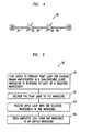
- FIG 5 is a flow chart for a process 50 that amplifies light with a Raman amplifier 10, 10' of Figure 1 or 2.
- the process 50 tunes wavelength-tunable pump laser 12 to produce pump light whose wavelength is capable of causing Raman amplification in chalcogenide glass waveguide 14 in response to input light of a selected wavelength (step 51).
- the tuning may be performed by an operator or a programmable computer 24 that operates the wavelength-tunable pump laser 12. If the computer 24 controls the pump laser 14, the computer 24 looks up an appropriate pump light wavelength in a database look up table in response to an external request to amplify input light with the selected wavelength.
- the choice of pump light wavelength depends on phonon spectrum of the chalcogenide glass and the selected wavelength to be amplified.
- output light is produced by Raman events stimulated by the input light signal. The stimulated events occur due to the background intensity of pump light.
- a stimulated Raman event a pump photon produces both a stimulated photon and a stimulated phonon.
- the original energy and momentum of the pump photon is divided between the stimulated photon and phonon. This dividing of the original energy and momentum implies that the stimulated light has a longer wavelength than the pump light that produced the stimulated light.
- the pump photon Since the stimulated light has the same wavelength as the input light, the pump photon must have an energy equal to the sum of the energy of the input photon plus the energy of the stimulated phonon. Thus, the pump light wavelength has a shift with respect to the input light wavelength, which is caused by phonon production.
- the size of the wavelength shift between the pump and input light depends on physical characteristics of the amplifier glass.
- the pump light wavelength is chosen to equal the input light wavelength minus the phonon-related wavelength shift associated with the particular chalcogenide glass used in amplifier waveguide 14. Phonon-related wavelength shifts are known and easily measurable by methods known to those of skill in the art.
- the choice of pump light wavelength has some freedom due to the breadth of the Raman scattering cross section.
- the scattering cross section gives the probability of a Raman event as a function of the shift between wavenumbers of pump and input light.
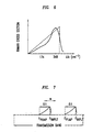
- Figure 6 illustrates the Raman scattering cross section of As 40 S 60 glass as a function of wavenumber shift, ⁇ k.
- the Raman cross section defines a window "w" of available choices for the pump light wavelength, ⁇ PUMP .
- Figure 7 illustrates the window "w” of pump light wavelengths, ⁇ PUMP , for a selected input light wavelength, ⁇ INPUT .
- the phonon-induced wavelength shift is also shown for the chalcogenide glass used in the particular amplifier waveguide.
- the window "w" is smaller than the optical transmission band for input light, e.g., the transmission band may be a complete set of channels of a DWDM network.
- the wavelength-tunable pump laser 12 may be retuned to produce a new pump wavelength, ⁇ ' PUMP , for amplifying a later-received input signal with a new wavelength, ⁇ ' INPUT , that is outside of the original window "w".
- compositions of amplifier media can be selected to produce amplification in a broader band of wavelengths for a particular choice of pump light wavelength.
- One way to broaden the amplification band entails making the amplifier waveguide of a mixture of two or more binary chalcogenide compounds with different phonon-induced Raman shifts.
- the amplifier waveguide may be a mixture of As 40 S 60 glass and As 40 Se 60 glass, which have respective Raman wavelength shifts of 85 and 55 nanometers (nm).
- the total Raman scattering cross section is a sum of the individual scattering cross sections for the binary glasses in the mixture.
- process 50 delivers pump light from wavelength-tunable pump laser 12 to chalcogenide glass amplifier waveguide 14 after choosing the pump light wavelength (step 52).
- the chalcogenide glass amplifier waveguide 14 receives input light, e.g., a sequence of digital optical pulses, with the selected input light wavelength from input waveguide 18 (step 53).
- the input light and simultaneously delivered pump light produce stimulated Raman emission in the amplifier waveguide 14 causing amplification of the input light therein.
- the process 50 sends light from the chalcogenide glass amplifier waveguide 14 to an output, e.g., output waveguide 20 or simply from an end of the amplifier waveguide 14 (step 54).
- the process 50 may also pass the light from the amplifier waveguide 14 through a filter that selectively removes pump light prior to sending the light to the output waveguide 20.
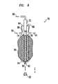
- FIG 8 is a cross-sectional view of an apparatus 70 for drawing chalcogenide glass amplifier fiber 26 shown in Figure 3.
- the apparatus 70 includes inner and outer cylinders 72, 74 for holding separate chalcogenide glass preforms 76, 78 for making the fiber's core 24 and cladding 26, respectively.
- the inner and outer cylinders 72, 74 are concentric and have inner diameters of about 5-20 mm and 10-100 mm, respectively.
- the cylinders 72, 74 are made of quartz, platinum, or an alloy of platinum.
- the glass preform 76 has the composition of fiber core 27 and a rod-like shape that enables sliding the preform 76 into the inner cylinder 72.
- the glass preform 78 has the composition of fiber cladding 28 and a tubular shape that enables sliding the preform 78 into the separate tubular space between the inner and outer cylinders 72, 74.
- Each cylinder 72, 74 tapers at a lower end to form a tubular draw port 80, 82.
- upper and lower make reference to directions with respect the direction "z" of gravity.
- the draw ports 80, 82 of the inner cylinder 72 have inner diameters of about 0.1-20 mm and 0.2-30 mm, respectively.
- the lower end of the inner port 80 is 0.5-5 mm upward from the lower end of the outer draw port 82.
- Concentric and vertical relative alignments between inner and outer cylinders 72, 74 are achieved through matched conical seating sections 84, 86.
- the seating sections 84, 86 also seal the upper region between the inner and outer cylinders 72, 74 from the external ambient atmosphere, i.e., the seal prevents external gases from entering the region above the preform 78.
- Adjustable ports 88-91 enable control of gas pressures in the regions above glass preforms 76, 78 during fiber drawing as well as introduction of gases into and removal of gases from these regions.
- a removable plug 92 may be positioned to close ports 80, 82 and seal space below the glass preforms 76, 78 thereby stopping the escape of glass during melting.
- Outer cylinder 74 is supported by a cylindrical metal body 94, i.e., made of an Iconel alloy or platinum.
- the metal body 94 is tapered at the lower end to physically retain the outer cylinder 74 from falling.
- the body 94 forms a thermal contact between outer cylinder 74 and an adjustable heater 96.
- drawing apparatus 70 One construction for drawing apparatus 70 is described in U.S. 5,900,036, which is incorporated herein by reference in its entirety.
- Alternate apparatus and processes for drawing chalcogenide fibers are described in U.S. Patents 5,879,426 and 6,021,649, which are also incorporated herein by reference in their entirety.
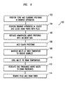
- Figure 9 is a flow chart for a process 100 of making chalcogenide glass fibers with drawing apparatus 70 of Figure 8.
- the process 100 positions separate glass preforms 76, 78 for fiber core 27 and cladding 28 in cylinders 72, 74 and seats sections 84, 86 to seal the region above cylinders 72, 74 from external gases (step 102).
- the process 100 positions the outer cylinder 74 in metal body 94 of heater 96 and closes ports 80, 82 with plug 92 (step 104).
- ports 88-91 are used to replace atmospheres in regions above the glass preforms 76, 78 with an inert gas such as nitrogen or helium (step 105).
- the heater 96 is also regulated to slowly heat the forms 76, 78 to temperatures that cause the chalcogenide glasses of the preforms 76, 78 to melt (step 106).
- the process 100 maintains the melts from the preforms 76, 78 above melting temperatures for a sufficient period to remove bubbles from the melts, e.g., 0.25-6 hours (step 108). Then the process 100 cools the melts to a draw temperature over a period of 2-10 minutes (step 110). At the draw temperature, the chalcogenide materials have viscosities of 10 3 to 10 7 poises.
- ports 88-91 are operated to fix gas pressures over the core melt located inside inner cylinder 72 and the cladding melt located between inner and outer cylinders 72, 74 to selected draw pressures (112).
- the relative gas pressures over the two chalcogenide glass melts determine the relative diameters of core 27 and cladding 28 produced by the draw.
- Fibers with relatively thinner cores are produced by maintaining a relatively lower gas pressure over the core glass melt located in the inner cylinder 72 than over the cladding glass melt located between the cylinders 72, 74.
- the plug 92 is removed and fiber is drawn from ports 80, 82 (step 114). Gas pressures are maintained at values of about 0.01 to 30 pounds per square inch above ambient external pressures to produce draw rates of about 1 to 10 meters of fiber per minute.
- draw pressures of 25.4 mm of water and 0.5 pounds-per-square-inch over respective melts of core and cladding glass produce a chalcogenide fiber with a As 40 S 58 Se 2 core 27 having a diameter of 14 ⁇ m and a As 2 S 3 cladding 28 having an outer diameter of 130 ⁇ m.
- port 82 has an inner diameter of about 5 mm
- port 80 has an inner diameter of about 1 mm and a low end positioned about 0.5 mm upward from the lower end of the port 82.
Landscapes
- Physics & Mathematics (AREA)
- Electromagnetism (AREA)
- Engineering & Computer Science (AREA)
- Plasma & Fusion (AREA)
- Optics & Photonics (AREA)
- Lasers (AREA)
- Glass Compositions (AREA)
- Optical Modulation, Optical Deflection, Nonlinear Optics, Optical Demodulation, Optical Logic Elements (AREA)
Abstract
Description
- This invention relates to Raman optical amplifiers.
- To compensate attenuation, optical communication systems often provide for amplification of optical signals at regular intervals along optical transmission fibers. The amplification may be produced by amplifiers based on rare-earth elements such as erbium and ytterbium or by amplifiers based on the Raman effect. Rare-earth amplifiers have limited bandwidth due to their reliance on selected atomic level transitions. Amplification occurs at discrete wavelengths that correspond to the selected atomic transitions. Broadband erbium doped fiber amplifiers are somewhat improved rare earth amplifiers so that these rare-earth amplifiers can power some wavelength division multiplexed (WDM) optical networks. On the other hand, Raman amplifiers are naturally tunable and capable of providing amplification at wavelengths in a broad optical band. In such an amplifier, an amplification wavelength is simply selected by tuning a pump laser to produce a wavelength capable of producing stimulated Raman emission at the selected wavelength. Raman amplifiers can cover a much wider spectral range than rare-earth based amplifiers. Furthermore, Raman amplifiers have effectively lower noise levels than rare-earth amplifiers. These advantages make Raman amplifiers desirable for long haul WDM systems where the transmission bandwidth may be broad.
- Nevertheless, conventional Raman fiber amplifiers provide relatively low gain. In such amplifiers, an optical signal often has to propagate through a long and heavily pumped amplifier fiber to receive adequate amplification. For example, to produce a 20-dB amplification, some conventional Raman fiber amplifiers use 10 to 100 kilometers (km) of amplifier fiber and 300 to 1,000 milli-Watts (mW) of pump light. High pump light powers require expensive pump lasers and incur higher operating costs for pump lasers. Raman amplifiers based on shorter amplifier fibers and lower pumping powers are desirable.
- In one aspect, the invention features an optical amplifier including a chalcogenide glass optical waveguide with optical input and output ports, a pump optical waveguide, and a wavelength-tunable pump laser. The pump optical waveguide couples the wavelength-tunable pump laser to the chalcogenide glass optical waveguide.
- In a second aspect, the invention features a method of amplifying light. The method includes tuning a wavelength-tunable pump laser to produce pump light with a wavelength capable of causing Raman amplification in a chalcogenide glass optical waveguide in response to light of a selected wavelength being received in the chalcogenide glass optical waveguide. The method also includes delivering the pump light to the chalcogenide glass optical waveguide, and receiving input light with the selected wavelength in the chalcogenide glass optical waveguide.
- In a third aspect, the invention features an optical communication system. The system includes a plurality of silica glass optical fibers and at least one Raman amplifier coupled between two of the silica glass optical fibers. The Raman amplifier of the present invention includes a chalcogenide glass optical waveguide connecting the two of the silica optical fibers, a pump optical waveguide, and a wavelength-tunable pump laser. The pump optical waveguide couples the pump laser to the chalcogenide glass optical waveguide.
-
- Figure 1 shows one embodiment of a Raman amplifier;
- Figure 2 shows an alternate embodiment of a Raman amplifier;
- Figure 3 is a cross-sectional view of a chalcogenide glass fiber used in some embodiments of the Raman amplifiers of Figures 1 and 2;
- Figure 4 shows a portion of an optical communications network that uses the Raman amplifiers of Figure for 2;
- Figure 5 is a flow chart showing a process for amplifying light with the Raman amplifiers of Figure 1 or 2;
- Figures 6 and 7 graphically illustrate the relationship between the wavelengths of pump light and input light in the process of Figure 5;
- Figure 8 shows a apparatus for drawing a chalcogenide glass fiber for use in some embodiments of the Raman amplifiers of Figures 1 and 2; and
- Figure 9 is a flow chart showing one process for making chalcogenide glass fibers for use in some embodiments of the Raman amplifiers of Figures 1 and 2.
-
- Various embodiments provide improved Raman amplification by using optical amplification media made of chalcogenide glass instead of optical amplification media made of silica or other oxide glasses.
- Figure 1 shows one embodiment of a
Raman amplifier 10 in which a wavelength-tunable pump laser 12 couples to an input port of a chalcogenideglass amplifier waveguide 14 via a 2x1optical connector 16. The wavelength-tunability of thepump laser 12 enables amplification of light belonging to a wide band of wavelengths unlike conventional rare-earth based amplifiers in which the amplification wavelength is not tunable and pumping sources are thus, not wavelength tunable. In various embodiments, theamplifier medium 14 is either an optical fiber or a planar waveguide. - The
optical connector 16 also connects aninput waveguide 18, e.g., a silica optical transmission fiber, to the input port of the chalcogenideglass amplifier waveguide 14. An output port of the chalcogenideglass amplifier waveguide 14 couples to anoutput waveguide 20, e.g., another silica optical transmission fiber, via anoptical coupler 22. In some embodiments, thecoupler 22 selectively filters out light at wavelengths produced by thepump laser 12 so that pump light is not transmitted to theoutput waveguide 20. - By using an amplification medium of chalcogenide glass, Raman
amplifier 10 improves the gain over gains available from silica-glass Raman amplifiers. The origin of the improvement can be understood from an approximate equation for a waveguide's Raman gain, G. The equation states that G = K'egIL. Here, "g" is the Raman gain coefficient, L is the length of the amplifier waveguide, and I is the pump light intensity. The Raman gain cross section is proportional to the Kerr coefficient, n2. Thus, the Raman gain (G) depends exponentially on the product of the Kerr coefficient, n2, and the pump light intensity, I. - The exponential dependence on n2 implies that many chalcogenide glasses will produce much larger Raman gains than silica-glasses, because the n2's of those chalcogenide glasses are much larger than the n2's of silica glasses. For example, some chalcogenide glasses based on Se compounds have n2's that are about 50 to 1,000 times as large as the n2's of silica glasses, i.e., at least 50 or 200 times the n2 of undoped silica glass. The Raman
amplifier 10 uses one of the high n2 chalcogenide glasses for the optical core ofamplifier waveguide 14. - The equation for gain (G) also provides guidance for determining the length of the chalcogenide glass fiber, because the total amplification depends on the product LIn2. For example, to produce the same amplification as a silica-based Raman amplifier for which LI is about (10 kilometers) (500 mW), the Raman
amplifier 10 only needs to have a length times power value of about 25,000 to 5,000 meter-mW. Various amplifiers use less than 500 meters of chalcogenide fiber and a pump source that produces less than 500-mW of pump light due to the increased n2 of chalcogenide glasses. For example, a 100-meter length of chalcogenide fiber and a 50-250 mW pump source is able to produce as much amplification as 10-kilometer (km) of silica-based Raman amplifier fiber and a 500-mW pump source. - Herein, chalcogenide glass is defined to be an amorphous material that transmits visible and near infrared light and includes a compound of selenium (Se), tellurium (Te), and/or sulfur (S) with one or more other elements. The combined molar percentage of Se, Te, and/or S is typically at least 25 percent. In the compounds, examples of the other elements include germanium (Ge), arsenic (As), tin (Sb), thallium (Tl), lead (Pb), phosphorous (P), gallium (Ga), indium (In), lanthium (La), silicon (Si), chlorine (Cl), bromine (Br), iodine (I), and a rare earth element. The chalcogenide glasses are not oxide glass unlike standard silica optical glasses.
- Figure 2 shows an alternate embodiment of a Raman amplifier 10' in which wavelength-
tunable pump laser 12 couples to one end of chalcogenideglass amplifier waveguide 14 andinput waveguide 18 couples to the other end of the chalcogenideglass amplifier waveguide 14. In the amplifier 10', pump light and input light counter- propagate in theamplifier waveguide 14 so that pump light does not appear inoutput waveguide 20. - In some embodiments of
amplifier 10 or 10' shown in Figures 1 and 2,waveguide 14 is a chalcogenide glass optical fiber. Figure 3 is a cross-sectional view of a chalcogenideglass amplifier fiber 26 used in such embodiments. Thefiber 26 includes achalcogenide glass core 27 and achalcogenide glass cladding 28. Thecore 27 has a diameter of about 2-14 microns (µm) and a preferable diameter of less than about 5 µm. Thecladding 28 has an outer diameter of about 120-130 µm. -
Core 27 andcladding 28 are made of chalcogenide glasses with different chemical compositions so that a jump in index of refraction occurs at the core-cladding interface. To provide for total internal reflection of light propagating inamplifier fiber 26, thecore 27 has an index of refraction, ncore, that is higher than the index of refraction, ncladding, of thecladding 28. To insure single-mode operation in theamplifier fiber 26, thefiber 26 is single modal, has fractional jump in index of refraction at the core-cladding interface, i.e., Δ = [ncore - ncladding]/ncladding, of between 1 and 5 percent, and has a Vnumber of less than about 2.4. Here, Vnumber = (πD/λ)(ncore 2 - ncladding 2)½, D is the core diameter, and λ is the wavelength of the light propagating in theamplifier fiber 26. In WDM systems, λ is between about 1.3 and 1.6 microns. - As an example, the
core 27 may be made of As40Se60 glass, which has an index of about 2.7, and thecladding 28 may be made of As40S60, which has an index of about 2.4. Then, Δ = 1.25, and thecore 27 has a diameter of less than about 3 microns to insure single-mode propagation of the light whose wavelength is about 1.5 microns. - In some embodiments,
core 27 is made of As40-40ySe60-60yS100y, Ge28Se60Sb12, Ge25Se65-67, Te8-10, or As50Se35Cu15, andcladding 28 is made of As40-40xSe60-60xS100x. - The choice of chalcogenide glass for the
core 27 depends on the desired Raman gain, G. The gain depends on the Kerr coefficient of the core's glass. As40Se60 glass has a large Kerr coefficient, which improves the amplifier's gain. For long amplifier fibers, the gain also depends 2-photon absorption that generate pump light losses. Low 2-photon absorption rates occur, increasing the overall gain, if the chosen core glass has a bandgap that is larger than twice the energy of the desired pump light photons. U.S. patent application No. 09/399,625, filed Sept. 20, 1999, by H.Y. Hwang et al describes methods for choosing the glass composition for thecore 27 and is incorporated by reference herein, in its entirety. - The choice of molar percentage of sulfur (S), i.e., 100x, in the
cladding 28 depends on the above-discussed constraints on Vnumber and Δ, which insure single-mode operation. The index of refraction of As40-40xSe60-60xS100x varies approximately linearly from 2.7 to 2.4 as 100x varies from 0 to 100 percent so that the molar percentage "100x" in thecladding 28 can be chosen to satisfy the constraints for single modal operation. - Figure 4 shows an
optical communications network 30 that uses variable wavelength, chalcogenide glass,Raman amplifiers 32; e.g.,amplifiers 10, 10' of Figures 1 and 2. Theamplifiers 32 are regularly spaced between sequential segments 34-36 of an optical transmission fiber, e.g., segments made of multimodal silica-glass fibers. The segments 34-36 form a transmission pathway optically connectingoptical transmitter 38 tooptical receiver 40. The lengths of the segments 34-36 of transmission fiber are short enough to insure that accumulated attenuations are less than about 20 decibels (dB) before the next stage of amplification. For example, modern silica-based transmission fibers produce an attenuation of about 0.2 dB per kilometer (km) for wavelengths between about 1.3 and 1.6 µ. For such fibers, individual segments 34-36 are not longer than about 80 km. - Figure 5 is a flow chart for a
process 50 that amplifies light with aRaman amplifier 10, 10' of Figure 1 or 2. Prior to receiving input light, theprocess 50 tunes wavelength-tunable pump laser 12 to produce pump light whose wavelength is capable of causing Raman amplification inchalcogenide glass waveguide 14 in response to input light of a selected wavelength (step 51). The tuning may be performed by an operator or aprogrammable computer 24 that operates the wavelength-tunable pump laser 12. If thecomputer 24 controls thepump laser 14, thecomputer 24 looks up an appropriate pump light wavelength in a database look up table in response to an external request to amplify input light with the selected wavelength. - The choice of pump light wavelength depends on phonon spectrum of the chalcogenide glass and the selected wavelength to be amplified. In a Raman amplifier output light is produced by Raman events stimulated by the input light signal. The stimulated events occur due to the background intensity of pump light. In a stimulated Raman event, a pump photon produces both a stimulated photon and a stimulated phonon. Thus, the original energy and momentum of the pump photon is divided between the stimulated photon and phonon. This dividing of the original energy and momentum implies that the stimulated light has a longer wavelength than the pump light that produced the stimulated light. Since the stimulated light has the same wavelength as the input light, the pump photon must have an energy equal to the sum of the energy of the input photon plus the energy of the stimulated phonon. Thus, the pump light wavelength has a shift with respect to the input light wavelength, which is caused by phonon production.
- Similar to other phonon-related properties, the size of the wavelength shift between the pump and input light depends on physical characteristics of the amplifier glass. The pump light wavelength is chosen to equal the input light wavelength minus the phonon-related wavelength shift associated with the particular chalcogenide glass used in
amplifier waveguide 14. Phonon-related wavelength shifts are known and easily measurable by methods known to those of skill in the art. - The choice of pump light wavelength has some freedom due to the breadth of the Raman scattering cross section. The scattering cross section gives the probability of a Raman event as a function of the shift between wavenumbers of pump and input light.
- Figure 6 illustrates the Raman scattering cross section of As40S60 glass as a function of wavenumber shift, Δk. The wavenumber shift satisfies: Δk = kpump - kinput where kpump and kinput are wavenumbers of the pump and input light, respectively. The Raman scattering cross section has an approximately linear dependence on Δk and has a peak at Δk = 348 cm-1. Choosing the wavenumber of the pump light, kpump, to equal the wavenumber of the input light, kinput, plus 348 cm-1 provides a high probability of Raman scattering and strong Raman amplification in As40S60 glass waveguides.
- But, other pump light wavelengths for which Raman scattering cross sections are large, e.g., at least half the maximum cross section, are also possible choices for the pump light wavelength. Thus, the Raman cross section defines a window "w" of available choices for the pump light wavelength, λPUMP. Figure 7 illustrates the window "w" of pump light wavelengths, λPUMP, for a selected input light wavelength, λINPUT. The phonon-induced wavelength shift is also shown for the chalcogenide glass used in the particular amplifier waveguide. In the example, the window "w"is smaller than the optical transmission band for input light, e.g., the transmission band may be a complete set of channels of a DWDM network. The wavelength-
tunable pump laser 12 may be retuned to produce a new pump wavelength, λ'PUMP, for amplifying a later-received input signal with a new wavelength, λ'INPUT, that is outside of the original window "w". - Compositions of amplifier media, i.e.,
waveguide 14 of Figures 1 and 2, can be selected to produce amplification in a broader band of wavelengths for a particular choice of pump light wavelength. One way to broaden the amplification band entails making the amplifier waveguide of a mixture of two or more binary chalcogenide compounds with different phonon-induced Raman shifts. For example, the amplifier waveguide may be a mixture of As40S60 glass and As40Se60 glass, which have respective Raman wavelength shifts of 85 and 55 nanometers (nm). For such a ternary mixture, the total Raman scattering cross section is a sum of the individual scattering cross sections for the binary glasses in the mixture. This can result in a total scattering cross section that no longer has a linear dependence on shifts as shown in Figure 6. Rather the mixture may have multiple peaks so that input signals with wavelengths for which the Raman cross section has a value at least half as large as one of the peak values would be amplified by the same pump light wavelength. - Referring again to Figure 5,
process 50 delivers pump light from wavelength-tunable pump laser 12 to chalcogenideglass amplifier waveguide 14 after choosing the pump light wavelength (step 52). The chalcogenideglass amplifier waveguide 14 receives input light, e.g., a sequence of digital optical pulses, with the selected input light wavelength from input waveguide 18 (step 53). The input light and simultaneously delivered pump light produce stimulated Raman emission in theamplifier waveguide 14 causing amplification of the input light therein. Theprocess 50 sends light from the chalcogenideglass amplifier waveguide 14 to an output, e.g.,output waveguide 20 or simply from an end of the amplifier waveguide 14 (step 54). Theprocess 50 may also pass the light from theamplifier waveguide 14 through a filter that selectively removes pump light prior to sending the light to theoutput waveguide 20. - Figure 8 is a cross-sectional view of an
apparatus 70 for drawing chalcogenideglass amplifier fiber 26 shown in Figure 3. Theapparatus 70 includes inner andouter cylinders core 24 andcladding 26, respectively. The inner andouter cylinders cylinders glass preform 76 has the composition offiber core 27 and a rod-like shape that enables sliding thepreform 76 into theinner cylinder 72. The glass preform 78 has the composition offiber cladding 28 and a tubular shape that enables sliding the preform 78 into the separate tubular space between the inner andouter cylinders - Each
cylinder tubular draw port draw ports inner cylinder 72 have inner diameters of about 0.1-20 mm and 0.2-30 mm, respectively. The lower end of theinner port 80 is 0.5-5 mm upward from the lower end of theouter draw port 82. - Concentric and vertical relative alignments between inner and
outer cylinders conical seating sections 84, 86. Theseating sections 84, 86 also seal the upper region between the inner andouter cylinders - Adjustable ports 88-91 enable control of gas pressures in the regions above glass preforms 76, 78 during fiber drawing as well as introduction of gases into and removal of gases from these regions. Similarly, a
removable plug 92 may be positioned to closeports -
Outer cylinder 74 is supported by acylindrical metal body 94, i.e., made of an Iconel alloy or platinum. Themetal body 94 is tapered at the lower end to physically retain theouter cylinder 74 from falling. Thebody 94 forms a thermal contact betweenouter cylinder 74 and anadjustable heater 96. - One construction for drawing
apparatus 70 is described in U.S. 5,900,036, which is incorporated herein by reference in its entirety. Alternate apparatus and processes for drawing chalcogenide fibers are described in U.S. Patents 5,879,426 and 6,021,649, which are also incorporated herein by reference in their entirety. - Figure 9 is a flow chart for a
process 100 of making chalcogenide glass fibers with drawingapparatus 70 of Figure 8. Theprocess 100 positions separate glass preforms 76, 78 forfiber core 27 andcladding 28 incylinders seats sections 84, 86 to seal the region abovecylinders process 100 positions theouter cylinder 74 inmetal body 94 ofheater 96 and closesports heater 96 is also regulated to slowly heat theforms 76, 78 to temperatures that cause the chalcogenide glasses of thepreforms 76, 78 to melt (step 106). Theprocess 100 maintains the melts from thepreforms 76, 78 above melting temperatures for a sufficient period to remove bubbles from the melts, e.g., 0.25-6 hours (step 108). Then theprocess 100 cools the melts to a draw temperature over a period of 2-10 minutes (step 110). At the draw temperature, the chalcogenide materials have viscosities of 103 to 107 poises. - Next, ports 88-91 are operated to fix gas pressures over the core melt located inside
inner cylinder 72 and the cladding melt located between inner andouter cylinders core 27 andcladding 28 produced by the draw. Fibers with relatively thinner cores are produced by maintaining a relatively lower gas pressure over the core glass melt located in theinner cylinder 72 than over the cladding glass melt located between thecylinders plug 92 is removed and fiber is drawn fromports 80, 82 (step 114). Gas pressures are maintained at values of about 0.01 to 30 pounds per square inch above ambient external pressures to produce draw rates of about 1 to 10 meters of fiber per minute. - At a draw temperature of 345°C, draw pressures of 25.4 mm of water and 0.5 pounds-per-square-inch over respective melts of core and cladding glass produce a chalcogenide fiber with a As40S58Se2 core 27 having a diameter of 14 µm and a As2S3 cladding 28 having an outer diameter of 130µm. To make a fiber of these dimensions,
port 82 has an inner diameter of about 5 mm, andport 80 has an inner diameter of about 1 mm and a low end positioned about 0.5 mm upward from the lower end of theport 82. These draw conditions produce a draw rate of about three meters of fiber per minute. - Other embodiments of the invention will be apparent to those skilled in the art in light of the specification, drawings, and claims of this application.
Claims (10)
- An optical amplifier comprising:a chalcogenide glass optical waveguide having optical input and output ports;a pump optical waveguide; anda wavelength-tunable pump laser, the pump optical waveguide coupling the pump laser to the chalcogenide glass optical waveguide.
- The optical amplifier of claim 1, wherein the chalcogenide glass optical waveguide is an optical fiber.
- The optical amplifier of claim 2, wherein the optical fiber has a Kerr coefficient that is at least about 50 times as large as the Kerr coefficient of undoped silica glass.
- The optical amplifier of claim 1, wherein the pump laser is configured to produce light that causes stimulated Raman emission in the chalcogenide glass optical waveguide in response to light received in the chalcogenide waveguide from the input port.
- An optical communication system, comprising:a plurality of silica glass optical fibers;at least one Raman amplifier coupled between two of the silica optical fibers, the Raman amplifier comprising:a chalcogenide glass optical waveguide connecting the two of the silica glass optical fibers;a pump optical waveguide; anda wavelength-tunable pump laser, the pump optical waveguide coupling the pump laser to the chalcogenide glass optical waveguide of the Raman amplifier.
- The optical amplifier of claim 5 , further comprising one of an optical transmitter and an optical receiver, the one of an optical transmitter and an optical receiver being connected to the Raman amplifier via one of the silica glass optical fibers.
- A method of amplifying light, comprising:tuning a wavelength-tunable pump laser to produce pump light capable of causing Raman amplification in a chalcogenide glass optical waveguide in response to light of a selected wavelength;delivering the pump light to the chalcogenide glass optical waveguide;receiving input light with the selected wavelength in the chalcogenide glass optical waveguide; andsending amplified light from the chalcogenide glass optical waveguide to an output.
- The method of claim 7, wherein the pump light is delivered to the chalcogenide glass optical waveguide at a time of receipt of the input light therein.
- The method of claim 7, wherein the tuning includes changing the wavelength of light produced by the pump laser.
- The method of claim 7, wherein the amplification of the input light per kilometer of the waveguide per 100 mW of pump light power is at least as large as about 40 decibels.
Applications Claiming Priority (4)
| Application Number | Priority Date | Filing Date | Title |
|---|---|---|---|
| US22866500P | 2000-08-29 | 2000-08-29 | |
| US228665P | 2000-08-29 | ||
| US689213 | 2000-10-12 | ||
| US09/689,213 US6504645B1 (en) | 2000-08-29 | 2000-10-12 | Chalcogenide glass based Raman optical amplifier |
Publications (2)
| Publication Number | Publication Date |
|---|---|
| EP1184943A1 true EP1184943A1 (en) | 2002-03-06 |
| EP1184943B1 EP1184943B1 (en) | 2006-09-27 |
Family
ID=26922550
Family Applications (1)
| Application Number | Title | Priority Date | Filing Date |
|---|---|---|---|
| EP01302211A Expired - Lifetime EP1184943B1 (en) | 2000-08-29 | 2001-03-12 | Chalcogenide glass based Raman amplifier |
Country Status (5)
| Country | Link |
|---|---|
| US (1) | US6504645B1 (en) |
| EP (1) | EP1184943B1 (en) |
| JP (1) | JP2002131792A (en) |
| CN (1) | CN1196021C (en) |
| DE (1) | DE60123352T2 (en) |
Cited By (3)
| Publication number | Priority date | Publication date | Assignee | Title |
|---|---|---|---|---|
| EP1345294A3 (en) * | 2002-03-15 | 2006-10-04 | Fitel Usa Corporation | Tunable multimode pump source for a Raman amplifier |
| EP1887420A2 (en) | 2004-03-30 | 2008-02-13 | Fujitsu Limited | Device for canceling the wavelength dependence of the nonlinearity coefficient of microstructured fibers |
| EP3724621A4 (en) * | 2017-12-11 | 2021-12-01 | SCHOTT Corporation | ATHERMIC GLASSES AND ATHERMIC SYSTEMS FOR INFRARED OPTICS |
Families Citing this family (9)
| Publication number | Priority date | Publication date | Assignee | Title |
|---|---|---|---|---|
| US6611368B1 (en) * | 2000-04-20 | 2003-08-26 | Lucent Technologies Inc. | Time-division multiplexed pump wavelengths resulting in ultra broad band, flat, backward pumped Raman gain |
| CA2443127A1 (en) * | 2001-04-12 | 2002-10-24 | Wesley King | High index-contrast fiber waveguides and applications |
| US6928227B2 (en) * | 2001-07-12 | 2005-08-09 | L. Brandon Shaw | Amplification with chalcogenide glass fiber |
| US20040137168A1 (en) * | 2002-11-22 | 2004-07-15 | Vladimir Fuflyigin | Dielectric waveguide and method of making the same |
| US8106586B1 (en) | 2004-04-26 | 2012-01-31 | Imaging Systems Technology, Inc. | Plasma discharge display with fluorescent conversion material |
| JP2007226072A (en) * | 2006-02-27 | 2007-09-06 | National Institute Of Information & Communication Technology | Optical device |
| US8952612B1 (en) | 2006-09-15 | 2015-02-10 | Imaging Systems Technology, Inc. | Microdischarge display with fluorescent conversion material |
| CN102856783B (en) * | 2012-09-14 | 2014-04-02 | 北京工业大学 | Intermediate/far infrared super-continuum spectrum fiber laser |
| WO2018232185A1 (en) * | 2017-06-14 | 2018-12-20 | Flir Commercial Systems, Inc. | Lens systems and methods of manufacture |
Citations (2)
| Publication number | Priority date | Publication date | Assignee | Title |
|---|---|---|---|---|
| EP0189196A2 (en) * | 1985-01-25 | 1986-07-30 | Polaroid Corporation | Raman amplified filter tap system |
| US5568497A (en) * | 1995-06-07 | 1996-10-22 | The Board Of Trustees Of The University Of Illinois | Chalcogenide optical pumping system having broad emission band |
Family Cites Families (11)
| Publication number | Priority date | Publication date | Assignee | Title |
|---|---|---|---|---|
| US5148510A (en) * | 1990-11-28 | 1992-09-15 | Corning Incorporated | Optical fiber made of galliobismuthate glasses and optical devices using same |
| JP2937285B2 (en) * | 1992-09-24 | 1999-08-23 | 日本電信電話株式会社 | Optical amplifier |
| JPH06214267A (en) * | 1993-01-14 | 1994-08-05 | Nippon Telegr & Teleph Corp <Ntt> | Nonlinear optical device |
| US5392376A (en) * | 1994-04-11 | 1995-02-21 | Corning Incorporated | Gallium sulfide glasses |
| JP3228462B2 (en) * | 1996-11-19 | 2001-11-12 | セントラル硝子株式会社 | Optical waveguide and 1.5 μm band optical amplifier using the same |
| JP3299684B2 (en) * | 1997-04-23 | 2002-07-08 | 日本電信電話株式会社 | Optical amplifier and optical amplification method |
| US6101024A (en) * | 1998-03-24 | 2000-08-08 | Xtera Communications, Inc. | Nonlinear fiber amplifiers used for a 1430-1530nm low-loss window in optical fibers |
| JP3794532B2 (en) * | 1998-07-27 | 2006-07-05 | 古河電気工業株式会社 | Raman amplification method |
| US6201916B1 (en) * | 1999-03-15 | 2001-03-13 | Lucent Technologies Inc. | Article comprising means for optical pulse reshaping |
| KR100340047B1 (en) * | 1999-10-11 | 2002-06-12 | 오길록 | Multi-component oxyhalide glass for optical amplifier and laser |
| JP3545977B2 (en) * | 1999-10-29 | 2004-07-21 | 日本電信電話株式会社 | Optical amplifier |
-
2000
- 2000-10-12 US US09/689,213 patent/US6504645B1/en not_active Expired - Lifetime
-
2001
- 2001-03-12 EP EP01302211A patent/EP1184943B1/en not_active Expired - Lifetime
- 2001-03-12 DE DE60123352T patent/DE60123352T2/en not_active Expired - Lifetime
- 2001-08-29 JP JP2001258868A patent/JP2002131792A/en active Pending
- 2001-08-29 CN CN01125851.9A patent/CN1196021C/en not_active Expired - Fee Related
Patent Citations (2)
| Publication number | Priority date | Publication date | Assignee | Title |
|---|---|---|---|---|
| EP0189196A2 (en) * | 1985-01-25 | 1986-07-30 | Polaroid Corporation | Raman amplified filter tap system |
| US5568497A (en) * | 1995-06-07 | 1996-10-22 | The Board Of Trustees Of The University Of Illinois | Chalcogenide optical pumping system having broad emission band |
Non-Patent Citations (2)
| Title |
|---|
| ASOBE M ET AL: "Third-order nonlinear spectroscopy in As/sub 2/S/sub 3/ chalcogenide glass fibers", JOURNAL OF APPLIED PHYSICS, 1 JUNE 1995, USA, vol. 77, no. 11, pages 5518 - 5523, XP002174842, ISSN: 0021-8979 * |
| MASUDA H ET AL: "1.65 mu m band fibre Raman amplifier pumped by wavelength-tunable amplified spontaneous emission light source", ELECTRONICS LETTERS, 26 NOV. 1998, IEE, UK, vol. 34, no. 24, pages 2339 - 2340, XP002174841, ISSN: 0013-5194 * |
Cited By (6)
| Publication number | Priority date | Publication date | Assignee | Title |
|---|---|---|---|---|
| EP1345294A3 (en) * | 2002-03-15 | 2006-10-04 | Fitel Usa Corporation | Tunable multimode pump source for a Raman amplifier |
| CN100334498C (en) * | 2002-03-15 | 2007-08-29 | 美国飞泰尔有限公司 | Computer program product, system and method for adjustable multimode wave division multi-channel multiplex Raman pump |
| EP1887420A2 (en) | 2004-03-30 | 2008-02-13 | Fujitsu Limited | Device for canceling the wavelength dependence of the nonlinearity coefficient of microstructured fibers |
| US8078026B2 (en) | 2004-03-30 | 2011-12-13 | Fujitsu Limited | Device for canceling the wavelength dependence of the nonlinearity coefficient of microstructured fibers |
| EP3724621A4 (en) * | 2017-12-11 | 2021-12-01 | SCHOTT Corporation | ATHERMIC GLASSES AND ATHERMIC SYSTEMS FOR INFRARED OPTICS |
| US12012360B2 (en) | 2017-12-11 | 2024-06-18 | Schott Corporation | Athermal glasses and athermal systems for infrared optics |
Also Published As
| Publication number | Publication date |
|---|---|
| DE60123352D1 (en) | 2006-11-09 |
| EP1184943B1 (en) | 2006-09-27 |
| JP2002131792A (en) | 2002-05-09 |
| DE60123352T2 (en) | 2007-04-19 |
| CN1360222A (en) | 2002-07-24 |
| US6504645B1 (en) | 2003-01-07 |
| CN1196021C (en) | 2005-04-06 |
Similar Documents
| Publication | Publication Date | Title |
|---|---|---|
| US5067789A (en) | Fiber optic coupling filter and amplifier | |
| US6266181B1 (en) | Tellurite glass, optical amplifier, and light source | |
| EP1184943B1 (en) | Chalcogenide glass based Raman amplifier | |
| AU632601B2 (en) | A double active-fiber optical amplifier having a wide-band signal wavelength | |
| CA1277404C (en) | Apparatus comprising raman-active optical fiber | |
| JP3730775B2 (en) | Tellurite glass, optical amplifier and light source using the tellurite glass | |
| JP3803310B2 (en) | Optical fiber amplifier | |
| JPH11281840A (en) | Double window WDM optical fiber communication | |
| GB2151868A (en) | Optical amplifiers | |
| CA2493689A1 (en) | Optical fiber for raman amplification | |
| EP0910141A1 (en) | Optically amplifying fiber and amplifier with such a fiber | |
| US5706124A (en) | Rare earth element-doped optical fiber amplifier | |
| US6628883B2 (en) | Silica glass composition with lasing properties, an optical waveguide and a method of amplifying optical signals | |
| CA2352378C (en) | Chalcogenide glass based raman optical amplifier | |
| JP2006114858A (en) | Optical fiber and optical fiber amplifier using the same | |
| US7336413B2 (en) | Nonlinear fiber, wavelength conversion method and wavelength conversion device | |
| JPH10229238A (en) | Optical fiber amplifier and optical amplification method | |
| Shixun et al. | Fabrication and gain performance of Er3+/Yb3+-codoped tellurite glass fiber | |
| Alsingery et al. | Development of Bismuth-Doped Fibers (BDFs) in Optical | |
| US20240228302A9 (en) | Bismuth-doped germanosilicate fiber for e and s band amplification | |
| JP4621456B2 (en) | Optical functional waveguide material and optical amplification medium, optical amplifier, laser device, light source | |
| JP4255077B2 (en) | Optical amplifier and light source | |
| KR100928273B1 (en) | Fiber Optic Amplifier with Transition Metal | |
| WO2001076024A1 (en) | Active optical fibre doped with rare earth elements | |
| JP2005251999A (en) | Optical functional waveguide material and optical amplification medium, optical amplifier, laser device, light source |
Legal Events
| Date | Code | Title | Description |
|---|---|---|---|
| PUAI | Public reference made under article 153(3) epc to a published international application that has entered the european phase |
Free format text: ORIGINAL CODE: 0009012 |
|
| 17P | Request for examination filed |
Effective date: 20010322 |
|
| AK | Designated contracting states |
Kind code of ref document: A1 Designated state(s): DE FR GB Kind code of ref document: A1 Designated state(s): AT BE CH CY DE DK ES FI FR GB GR IE IT LI LU MC NL PT SE TR |
|
| AX | Request for extension of the european patent |
Free format text: AL;LT;LV;MK;RO;SI |
|
| AKX | Designation fees paid |
Free format text: DE FR GB |
|
| 17Q | First examination report despatched |
Effective date: 20050613 |
|
| GRAP | Despatch of communication of intention to grant a patent |
Free format text: ORIGINAL CODE: EPIDOSNIGR1 |
|
| RTI1 | Title (correction) |
Free format text: CHALCOGENIDE GLASS BASED RAMAN AMPLIFIER |
|
| GRAS | Grant fee paid |
Free format text: ORIGINAL CODE: EPIDOSNIGR3 |
|
| GRAA | (expected) grant |
Free format text: ORIGINAL CODE: 0009210 |
|
| AK | Designated contracting states |
Kind code of ref document: B1 Designated state(s): DE FR GB |
|
| REG | Reference to a national code |
Ref country code: GB Ref legal event code: FG4D |
|
| REF | Corresponds to: |
Ref document number: 60123352 Country of ref document: DE Date of ref document: 20061109 Kind code of ref document: P |
|
| ET | Fr: translation filed | ||
| PLBE | No opposition filed within time limit |
Free format text: ORIGINAL CODE: 0009261 |
|
| STAA | Information on the status of an ep patent application or granted ep patent |
Free format text: STATUS: NO OPPOSITION FILED WITHIN TIME LIMIT |
|
| 26N | No opposition filed |
Effective date: 20070628 |
|
| REG | Reference to a national code |
Ref country code: GB Ref legal event code: 732E Free format text: REGISTERED BETWEEN 20131121 AND 20131127 |
|
| REG | Reference to a national code |
Ref country code: FR Ref legal event code: CD Owner name: ALCATEL-LUCENT USA INC. Effective date: 20131122 |
|
| REG | Reference to a national code |
Ref country code: FR Ref legal event code: GC Effective date: 20140410 |
|
| REG | Reference to a national code |
Ref country code: FR Ref legal event code: RG Effective date: 20141015 |
|
| REG | Reference to a national code |
Ref country code: FR Ref legal event code: PLFP Year of fee payment: 15 |
|
| REG | Reference to a national code |
Ref country code: FR Ref legal event code: PLFP Year of fee payment: 16 |
|
| REG | Reference to a national code |
Ref country code: FR Ref legal event code: PLFP Year of fee payment: 17 |
|
| REG | Reference to a national code |
Ref country code: FR Ref legal event code: PLFP Year of fee payment: 18 |
|
| REG | Reference to a national code |
Ref country code: GB Ref legal event code: 732E Free format text: REGISTERED BETWEEN 20190131 AND 20190206 |
|
| REG | Reference to a national code |
Ref country code: DE Ref legal event code: R081 Ref document number: 60123352 Country of ref document: DE Owner name: PROVENANCE ASSET GROUP LLC, PITTSFORD, US Free format text: FORMER OWNER: LUCENT TECHNOLOGIES INC., MURRAY HILL, N.J., US |
|
| REG | Reference to a national code |
Ref country code: DE Ref legal event code: R081 Ref document number: 60123352 Country of ref document: DE Owner name: PROVENANCE ASSET GROUP LLC, PITTSFORD, US Free format text: FORMER OWNER: NOKIA OF AMERICA CORP. (N. D. GES. D. STAATES DELAWARE), MURRAY HILL, NJ, US Ref country code: DE Ref legal event code: R081 Ref document number: 60123352 Country of ref document: DE Owner name: PROVENANCE ASSET GROUP LLC, PITTSFORD, US Free format text: FORMER OWNER: ALCATEL-LUCENT USA INC. (N. D. GES. D. STAATES DELAWARE), MURRAY HILL, N.J., US |
|
| PGFP | Annual fee paid to national office [announced via postgrant information from national office to epo] |
Ref country code: GB Payment date: 20200323 Year of fee payment: 20 Ref country code: DE Payment date: 20200320 Year of fee payment: 20 |
|
| PGFP | Annual fee paid to national office [announced via postgrant information from national office to epo] |
Ref country code: FR Payment date: 20200319 Year of fee payment: 20 |
|
| REG | Reference to a national code |
Ref country code: DE Ref legal event code: R071 Ref document number: 60123352 Country of ref document: DE |
|
| REG | Reference to a national code |
Ref country code: GB Ref legal event code: PE20 Expiry date: 20210311 |
|
| PG25 | Lapsed in a contracting state [announced via postgrant information from national office to epo] |
Ref country code: GB Free format text: LAPSE BECAUSE OF EXPIRATION OF PROTECTION Effective date: 20210311 |