EP1184811A2 - Three-dimensional image processing method and apparatus and video game system - Google Patents
Three-dimensional image processing method and apparatus and video game system Download PDFInfo
- Publication number
- EP1184811A2 EP1184811A2 EP01119700A EP01119700A EP1184811A2 EP 1184811 A2 EP1184811 A2 EP 1184811A2 EP 01119700 A EP01119700 A EP 01119700A EP 01119700 A EP01119700 A EP 01119700A EP 1184811 A2 EP1184811 A2 EP 1184811A2
- Authority
- EP
- European Patent Office
- Prior art keywords
- shadow
- model
- vertices
- light source
- hidden
- Prior art date
- Legal status (The legal status is an assumption and is not a legal conclusion. Google has not performed a legal analysis and makes no representation as to the accuracy of the status listed.)
- Granted
Links
Images





Classifications
-
- G—PHYSICS
- G06—COMPUTING OR CALCULATING; COUNTING
- G06T—IMAGE DATA PROCESSING OR GENERATION, IN GENERAL
- G06T15/00—Three-dimensional [3D] image rendering
- G06T15/50—Lighting effects
- G06T15/60—Shadow generation
-
- A—HUMAN NECESSITIES
- A63—SPORTS; GAMES; AMUSEMENTS
- A63F—CARD, BOARD, OR ROULETTE GAMES; INDOOR GAMES USING SMALL MOVING PLAYING BODIES; VIDEO GAMES; GAMES NOT OTHERWISE PROVIDED FOR
- A63F2300/00—Features of games using an electronically generated display having two or more dimensions, e.g. on a television screen, showing representations related to the game
- A63F2300/60—Methods for processing data by generating or executing the game program
- A63F2300/66—Methods for processing data by generating or executing the game program for rendering three dimensional images
- A63F2300/6646—Methods for processing data by generating or executing the game program for rendering three dimensional images for the computation and display of the shadow of an object or character
Definitions
- the present invention relates to a three-dimensional (3D) image processing technique of applying a specified image processing to display a model located in a simulated three-dimensional (3D) space on a monitor after rendering it, which technique is applied, for example, to video game systems.
- an object of the present invention is to provide image processing method and apparatus for realistically and easily creating shadows of characters, a readable storage medium storing a 3D image processing program and a video game system.
- the present invention is related to a three-dimensional image processing apparatus for generating a shadow model of a solid model formed by polygons each having vertex normal vectors.
- Said three-dimensional image processing apparatus comprises a vertex sorting unit for sorting the respective vertices of the polygons forming the solid model into visible-surface vertices facing in a direction toward a light source and hidden-surface vertices facing in a direction opposite from the light source, and shadow model generating unit for deforming the solid model by moving the hidden-surface vertices in a propagating direction of rays from the light source.
- the shadow model can be easily generated using the model data of the polygon model for which a shadow is to be created.
- FIG. 1 is a block diagram showing one embodiment of a video game system according to the present invention.
- This game system 1 is provided with a main game unit, a television (TV) monitor 2 for displaying images of a game, an amplifying circuit 3 and a loudspeaker 4 for outputting sound effects and the like during a game, and a storage medium 5 storing game data including image data, sound data and program data.
- the storage medium 5 may be a ROM cassette in which a ROM storing the game data and a program data of an operating system is contained in a plastic casing, an optical disk, and a flexible disk.
- a built-in type ROM or the like may be used.
- the main game unit is constructed such that buses 7 including address busses, data buses and control buses are connected with a CPU 6; a RAM 8, interface circuits 9, 10, a signal processor 11, an image processor 12, and interface circuits 13, 14 are connected with the buses 7; a controller 16 is connected with the interface circuit 10 via an operational information interface circuit 15; a digital-to-analog (D/A) converter 17 is connected with the interface circuit 13; and a D/A converter 18 is connected with the interface circuit 14.
- buses 7 including address busses, data buses and control buses are connected with a CPU 6; a RAM 8, interface circuits 9, 10, a signal processor 11, an image processor 12, and interface circuits 13, 14 are connected with the buses 7; a controller 16 is connected with the interface circuit 10 via an operational information interface circuit 15; a digital-to-analog (D/A) converter 17 is connected with the interface circuit 13; and a D/A converter 18 is connected with the interface circuit 14.
- D/A digital-to-analog
- a memory unit 19 is constructed by the RAM 8, the interface circuit 9 and the storage medium 5; a control unit 20 for controlling the progress of the game is constructed by the CPU 6, the signal processor 11 and the image processor 12; an operation input unit 21 is constructed by the interface circuit 10, the operational information interface circuit 15 and the controller 16; an image display unit 22 is constructed by the TV monitor 2, the interface circuit 13 and the D/A converter 17; and a sound output unit 23 is constructed by the amplifying circuit 3, the loudspeaker 4, the interface circuit 14 and the D/A converter 18.
- the signal processor 11 mainly performs calculation of positions of characters in a simulated 3D space, calculation to transform a position in the simulated 3D space to the one in a two-dimensional (2D) space, light source calculation, and reading and combination of various sound data.
- the image processor 12 positions polygons forming an image to be formed in a display area of the RAM 8 and applies rendering such as texture mapping to these polygons based on the calculation result of the signal processor 11.
- the controller 16 is provided with various buttons for selecting game contents, instructing the start of the game, and instructing actions, direction, etc. to a main character.
- the mode of the game system 1 differs depending on its application. Specifically, the TV monitor 2, the amplifying circuit 3 and the loudspeaker 4 are separate from the main game unit in the case that the game system 1 is constructed for home use, whereas all the elements shown in FIG. 1 are contained as a unit in one casing in the case that the game system 1 is constructed for business use.
- the TV monitor 2 corresponds to a computer display
- the image processor 12 corresponds to part of the game program data stored in the storage medium 5 or hardware on an extension board mounted on an extension slot of the computer
- the interface circuits 9, 10, 13, 14, the D/A converters 17, 18, and the operational information interface circuit 15 correspond to hardware on the extension board mounted on the extension slot of the computer.
- the RAM 8 corresponds to a main memory of the computer or the respective areas of an extension memory.
- the game is proceeded by the CPU 6 in accordance with the game program data stored in the RAM 8 and contents of instructions given by a game player via the controller 16.
- commands as tasks for forming images and outputting sounds are suitably generated in accordance with contents of instructions given by the game player via the controller 16.
- the signal processor 11 performs calculation of positions of characters in the 3D space (of course the same applies for the 2D space), a light source calculation, reading and combination of various sound data in accordance with these commands.
- the image processor 12 writes the image data to be formed in the display area of the RAM 8 based on the calculation result of the signal processor 11.
- the image data written in the RAM 8 is supplied via the interface circuit 13 to the D/A converter 17, which then supplies the image data to the TV monitor 2 to display it as an image on the screen of the TV monitor 2 after converting it into an analog video signal.
- the sound data outputted from the signal processor 11 is supplied via the interface circuit 14 to the D/A converter 18, which in turn converts it into an analog sound signal (via a filter or the like).
- the converted signal is outputted as a game sound from the loudspeaker 4 as a sound generating means via the amplifying circuit 3.
- the game sounds refer to BGMs, various sound effects, presentation sounds, voices, etc.
- FIG. 2 is a block diagram showing an essential portion of a 3D image processing apparatus.
- the RAM 8 is provided with a polygon data section 80 for storing coordinates of vertices of the respective polygons, normal vectors of the respective vertices, normal vectors of surfaces of the polygons, and like data, a light source vector data section 81 for storing data on a vector representing a propagating direction of rays from a light source, a camera viewing vector data section 82 for storing data on a vector representing a viewing direction of a virtual camera, a shadow model generating data section 83 for storing data used to generate shadow models (shadow volumes), a frame buffer 8a for storing an image obtained by applying rendering to a polygon model located in the simulated 3D space, a stencil buffer 8b for storing a shadow image obtained by applying stenciling to the shadow model, and a Z-value data section 8c for storing distances Z between the viewpoint of the virtual camera and the polygons corresponding to the respective pixels in the simulated
- the polygon data section 80 includes a model data portion 801 for storing data on models for which shadow models are to be generated.
- the shadow model generating data section 83 includes a parallel movement amount data portion 831 representing an amount by which the model for which a shadow model is to be generated is moved in parallel to a display position to locate this model in the simulated 3D space, a rotation amount data portion 832 representing an amount of rotation of the model, a magnification data portion 833 representing a magnification (enlargement/reduction) of the model, a hidden-surface parallel movement data portion 834 representing how much a set of vertices of the respective polygons (here, referred to as "hidden-surface vertices.” Contrary to this, a set of vertices of the polygons upon which rays from the light source are projected are referred to as "visible-surface vertices") upon which rays from the light source are not projected should be moved in parallel in a direction of the light source vector, and a hidden-surface mag
- the signal processor 11 includes a shadow model generating device 111 for generating shadow models in a procedure to be described later.
- the image processor 12 includes a stenciling device 121 for generating a shadow image from the shadow model in a procedure called stenciling, an imaging device 122 for writing an image obtained by applying rendering to a polygon model located in the simulated 3D space in the frame buffer 8a and writing a shadow image in the stencil buffer 8b, and a combining device 123 for reading and combining the image written in the frame buffer 8a and the one written in the stencil buffer 8b and writing a combined image in the frame buffer 8a.
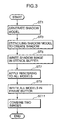
- FIG. 3 is a flow chart showing a summary of a 3D image processing applied to display a polygon model located in the simulated 3D space on the monitor 2 after applying rendering to it and to display a shadow of a specific polygon model on the monitor.
- a shadow model of a polygon model desired to be displayed with a shadow is generated by the shadow model generating device 111 (Step ST1).
- stenciling is applied to the shadow model by the stenciling device 121 to generate a shadow image (Step ST3).
- the generated shadow image is written in the stencil buffer 8b by the imaging device 122 (Step ST5).
- rendering is applied to all polygon models except the shadow model located in the simulated 3D space to obtain an image of the entire model except the shadow model (Step ST7).
- This image of the entire model except the shadow model is written in the frame buffer 8a by the imaging device 122 (Step ST9).
- the image written in the frame buffer 8a and the one written in the stencil buffer 8b are read and combined by the combining device 123 and the combined image is written in the frame buffer 8a (Step ST11).
- a polygon model used in the following description has vertex normal vector data corresponding to the respective vertices of the polygons forming the model and surface normal vector data corresponding to the respective surfaces of the polygons forming the model.
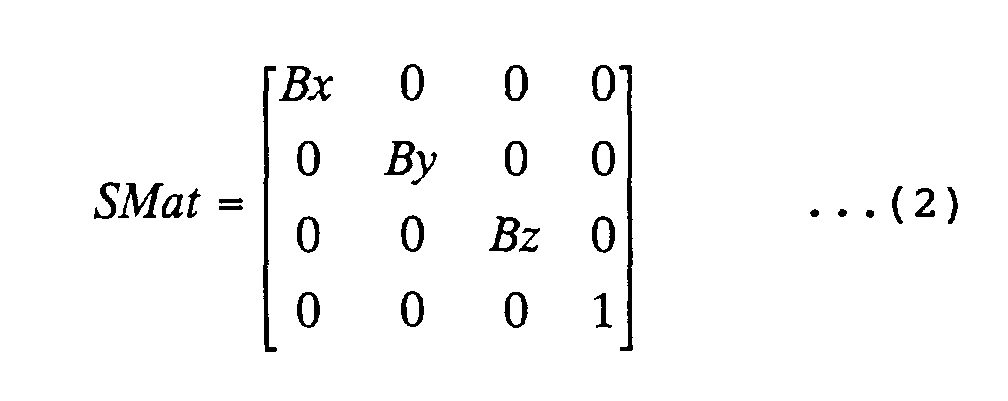
- Coordinate transform of the respective vertices of the polygon is specified by a magnification, a rotation amount and a parallel movement amount of the model.
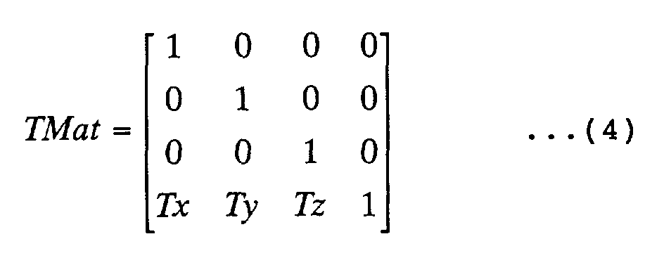
- an operation shown in Equation (1) is carried out in order to transform initial coordinates of a specific vertex from (x,y,z) to (x',y',z').
- Mat is a 4 ⁇ 4 matrix.
- SMat magnification matrix
- Equation (3) RMat (rotation matrix) shown in Equation (3) may be used as Mat of Equation (1).
- TRSMat shown in Equation (5) which is a product of TMat, RMat and SMat may be used as Mat of Equation (1).
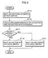
- FIG. 4 is a flow chart showing a procedure of generating the shadow model.
- a case where the hidden-surface vertices of the shadow model are not moved to enlarge or reduce areas of the hidden surfaces is described.
- vertex normal vectors when the polygon for which the shadow is to be created is located in the simulated 3D space are obtained by multiplying the vertex normal vectors of this polygon by the rotation matrix (Step ST13).
- Step ST15 an inner product of the vertex normal vector obtained in Step ST13 and the light source vector is calculated for each vertex of the polygon model for which the shadow is to be generated (Step ST15), and it is discriminated whether the obtained inner product is larger than "0" (Step ST17).
- this vertex is a vertex upon which rays from the light source are projected, and the vertex can be located in the simulated 3D space by multiplying the vertex normal vector by the matrix TRSMat (referred to as a visible-surface local matrix) shown in Equation (5) (Step ST19).
- TRSMat referred to as a visible-surface local matrix
- this vertex is a vertex upon which no ray from the light source is projected, and the vertex can be located in the simulated 3D space by multiplying the vertex normal vector by the matrix TRSMat' (referred to as a hidden-surface local matrix) shown in Equation (6) (Step ST21).
- Tz' Tz + k ⁇ Lz.
- (Lx,Ly,Lz) is a light source vector and k is a constant representing a distance of the hidden-surface vertex along the propagating direction of the rays from the light source which distance is stored in the hidden-surface parallel movement data section 834.
- the hidden-surface vertices are located in positions, which are reached by being moved in parallel by the distance k along the propagating direction of the rays from the light source from their positions when the polygon for which a shadow is to be created is located in the simulated 3D space.
- the shadow model includes visible-surface vertices located in the simulated 3D space in Step ST20 and hidden-surface vertices located therein in Step ST21.
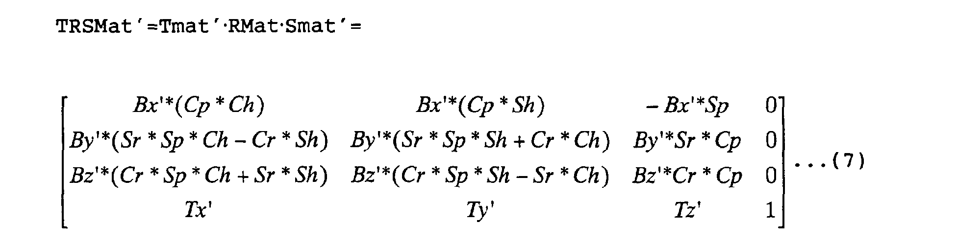
- a matrix TRSMat shown in Equation (7) may be used instead of the matrix TRSMat' used in Step ST21 in the case of moving the hidden-surface vertices to reduce or enlarge the areas of the hidden surfaces.
- BBx, BBy, BBz are stored in the hidden-surface magnification data portion 835 and represent magnifications at which the hidden-surface are magnified in X-axis, Y-axis and Z-axis directions, respectively.
- FIGS. 5A to 5D are diagrams showing shadow models of a spherical polygon M0 as examples.
- vertices included in sparsely dotted polygons are visible-surface vertices (M01, M11, M21, M31) and remaining vertices are hidden-surface vertices (M02, M12, M22, M32). Coordinate axes are shown next to FIG. 5D.
- FIG. 5A shows the spherical polygon model M0 for which a shadow model is to be generated.
- Parallel rays are incident on the polygon M0 in a direction of a shown light source vector V1, i.e. from right to left (negative direction along X-axis).
- Normal vectors V2 at the respective vertices are facing radially outward from the center of the spherical polygon M0. It can be seen that if an inner product of the normal vector V2 at the vertex and the light source vector V1 is positive, i.e. an X-component of the normal vector V2 at this vertex is facing in the same direction as the light source vector V1, this vertex is a hidden-surface vertex M02.
- FIG. 5B shows a shadow model M1 in the case that the hidden-surface vertices M02 are not moved to enlarge or reduce the areas of the hidden surfaces.
- the shadow model M1 is generated by moving the hidden-surface vertices M02 in parallel with the direction of the light source vector V1, i.e. in the negative direction of X-axis. If such a shadow model M1 is used, a shadow of a specified size is created regardless of a distance between a projection surface of the shadow and the model M0 in the simulated 3D space if this distance is equal to or smaller than a specified value.
- the shadow model M1 generated only by moving the hidden-surface vertices in parallel are suited to representing a shadow created when rays from the light sources are parallel rays as in this example.
- FIG. 5C shows an example of a shadow model M2 in the case that the hidden-surface vertices M02 are moved to reduce the areas of the hidden surfaces.
- the shadow model M2 is generated by moving the hidden-surface vertices M02 of FIG. 5A in parallel with the direction of the light source vector V1, i.e. in the negative direction of X-axis while reducing the areas of the hidden surfaces along Y-axis and Z-axis with respect to a center O of the polygon M0. If such a shadow model M2 is used, the size of a shadow to be created becomes smaller as a distance between a projection surface of the shadow and the model M0 in the simulated 3D space becomes larger if this distance is equal to or smaller than a specified value.
- the shadow model M2 generated by distance-reduction and parallel movements of the hidden-surface vertices is suited to representing a shadow created when the light source is a surface light source or a line light source.
- FIG. 5D shows an example of a shadow model M3 in the case that the hidden-surface vertices M02 are moved to enlarge the areas of the hidden surfaces.
- the shadow model M3 is generated by moving the hidden-surface vertices M02 of FIG. 5A in parallel with the direction of the light source vector V1, i.e. in the negative direction of X-axis while enlarging the areas of the hidden surfaces along Y-axis and Z-axis with respect to the center O of the polygon M0. If such a shadow model M3 is used, the size of a shadow to be created becomes larger as a distance between a projection surface of the shadow and the model M0 in the simulated 3D space becomes larger if this distance is equal to or smaller than a specified value.
- the shadow model M3 generated by distance-extension and parallel movements of the hidden-surface vertices is suited to representing a shadow created when the light source is a point light source.
- FIG. 6 is a flow chart showing a procedure of a processing called stenciling for generating a shadow image using a shadow model.
- rendering is applied by placing all polygon models including the shadow model in the simulated 3D space (Step ST25).
- RGB-values of the models displayed pixel by pixel of the screen are written, for example, in 8 bits (0 to 255) in the stencil buffer 8b.
- the distances Z from the viewpoint of the virtual camera to the model displayed in the respective pixels are written in the Z-value data section 8c.
- Step ST27 all the RGB-values in a memory of the stencil buffer 8b are initialized to 128 (represent white color) (Step ST27). Then, an inner product of the normal vector of each surface of the shadow model and the viewing vector of the camera is calculated (Step ST29) and it is discriminated whether the calculated inner product is larger than "0" (Step ST31).
- the surface an inner product larger than "0" is a surface (front-facing polygon) whose normal vector is facing in a direction opposite from the viewpoint of the camera and, for example, "1" is subtracted from the RGB-values of the pixels in the memory of the stencil buffer 8b corresponding to this surface (Step ST33).
- the surface having an inner product equal to or smaller than "0" is a surface (back-facing polygon) whose normal vector is facing in a direction toward the viewpoint of the camera and "1" is added to the RGB-values of the pixels in the memory of the stencil buffer 8b corresponding to this surface (Step ST35).
- Step ST37 128 is subtracted from all the RGB-values in the memory of the stencil buffer 8b (Step ST37). At this time, if the result of subtraction is a negative value, this negative value is replaced by "0". Then, shadow is created in the pixels whose RGB-values in the memory of the stencil buffer 8b are "1" or larger (Step ST39).
- a shadow image is created from the shadow model by the above processing. Although “1" is added or subtracted in the above calculation, any integer between 1 and 127 may be used.
- the pixels in which shadow is created are those having the front-facing polygon and having no back-facing polygon in the same pixel positions.
- the shadow model is a polygon model for clipping a closed space, no shadow is created if there is no projection surface of the shadow.
- the shadow is not created also in the case that the projection surface of the shadow is facing in a direction opposite from the viewpoint of the camera.
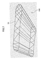
- FIGS. 7 and 8 are diagrams showing a shadow image of a snowboard thrown onto the surface of a slope which image is obtained by applying stenciling to a shadow model.
- FIG. 7 shows a shadow model M40 of a snowboard M4 in the case of moving the hidden-surface vertices to reduce areas of hidden surfaces.
- FIG. 8 is a diagram showing a shadow M5 of a snowboard M4 thrown on a surface M6 of a slope and a shadow model M41 clipped by the slope surface M6.
- the shadow model M41 clipped by the slope surface M6 includes (a) a plurality of front-facing polygons M411, M413 and (b) a plurality of back-facing polygons M412.
- the plurality of front-facing polygons include those polygons forming a portion of side surface that can be seen from the viewpoint of the camera and a top surface of the shadow model M41 that can be also seen from the viewpoint of the camera.
- the plurality of front-facing polygons include those polygons M411a, M411b, M411c, M411d, M411e, M411f, M411g, and M411h and those polygons forming the top surface M413a, M413b, M413c, M413d, M413e, M413f, M413g, M413h, M413i, and M413j.
- the shadow M5 is created by pixels corresponding to those pixels forming front-facing polygons (M411a + M411b + M411c + M411d + M411e + M411f + M411g + M411h + M413a + M413b + M413c + M413d + M413e + M413f + M413g + M413h + M413i + M413j) minus those pixels corresponding to back-facing polygons (M412a + M412b + M412c + M412d + M412e + M412f + M412g + M412h + M412i + M412j + M412k + M412l).
- Shadow M5 Summation of pixels corresponding to polygons ⁇ M411 and ⁇ M413 - Summation of pixels corresponding to polygons ⁇ M412.
- ⁇ M411 means M411a + M411b + M411c + M411d + M411e + M411f + M411g + M411h.
- ⁇ M412 means M412a + M412b + M412c + M412d + M412e + M412f + M412g + M412h + M412i + M412j + M412k + M412l.
- ⁇ M413 means M413a + M413b + M413c + M413d + M413e + M413f + M413g + M413h + M413i + M413j.
- the present invention may be embodied as follows.
- the present invention relates to a three-dimensional image processing apparatus for generating a shadow model of a solid model formed by polygons each having vertex normal vectors.
- the 3D image processing apparatus comprises vertex sorting means for sorting the respective vertices of the polygons forming the solid model into visible-surface vertices facing in a direction toward a light source and hidden-surface vertices facing in a direction opposite from the light source, and shadow model generating means for deforming the solid model by moving the hidden-surface vertices in a propagating direction of rays from the light source.
- the shadow model can be easily generated using the model data of the polygon model for which a shadow is to be created.
- the vertex sorting means may be configured to sort the vertices into the visible-surface vertices and the hidden-surface vertices based on whether an inner product of a normal vector of each vertex of each polygon and a light source vector representing the propagating direction of the rays from the light source is a positive or negative value. According to this construction, the visible-surface vertices and the hidden-surface vertices can be easily sorted out by calculating the inner products of the vectors.
- the shadow model generating means may be configured to move specified vertices in parallel with the propagating direction of the rays from the light source. According to this construction, shadows of a specific size are created regardless of a change in distance by which the characters of the models for which the shadows are created float from the ground surface, sea surface or other surface. Since such shadows behave in a manner similar to those actually created when the light source is a light source for emitting parallel rays such as sun rays, realistic and powerful images can be formed.
- the shadow model generating means may be configured to narrow distances between the specified vertices such that the hidden-surface vertices of the shadow model having the visible-surface vertices define a shape tapered in a moving direction. According to this construction, shadows thrown upon the ground surface, sea surface or other surface become smaller as the distances by which the characters of the models for which the shadows are created float from the ground surface, sea surface or other surface increase. Since such shadows behave in a manner similar to those actually created when the light source is a bar-shaped light source or a surface light source, realistic and powerful images can be formed.
- the shadow model generating means may be configured to widen distances between the specified vertices such that the hidden-surface vertices of the shadow model having the visible-surface vertices define a shape swollen in a moving direction. According tQ this construction, shadows thrown upon the ground surface, sea surface or other surface become larger as the distances by which the characters of the models for which the shadows are created float from the ground surface, sea surface or other surface increase. Since such shadows behave in a manner similar to those actually created when the light source is a point light source, realistic and powerful images can be formed.
- the aforementioned 3D image processing apparatus may further comprise a shadow creating means for sorting the polygons forming the shadow model into front-facing polygons facing in a direction toward a viewpoint of a virtual camera and back-facing polygons facing in a direction opposite from the viewpoint of the virtual camera, and creating a shadow image in pixels which are pixels corresponding to the front-facing polygons minus pixels corresponding to the back-facing polygons.
- a shadow can be easily created by applying a technique called stenciling to the shadow model.
- the aforementioned 3D image processing apparatus may further comprises a shadow creating means for creating a shadow image of the solid model using the shadow model, a first storage means for storing the created shadow image of the solid model, a second storage means for applying rendering to the polygon models except the shadow model and storing the thus created image, and a combining means for reading and combining the image stored in the first storage means and the one stored in the second storage means.
- the shadow model can be easily generated using the model data of the polygon model for which a shadow is to be created, and this shadow can be realistically and easily created.
- an entire image including the shadow of the solid model can be obtained by combining the shadow image of the solid model stored in the first storage means and the image other than the shadow image stored in the second storage means.
- the solid model may be a character movable in height direction in a simulated 3D space. According to this construction, since a shadow is created to follow a movement of the character along height direction, the movement of the character can be expressed in the realistic and powerful images.
- Another form of the present invention relates to a readable storage medium storing a 3D image processing program for generating a shadow model of a solid model formed by polygons each having vertex normal vectors, the program comprising the steps of: vertex sorting processing for sorting the respective vertices of the polygons forming the solid model into visible-surface vertices facing in a direction toward a light source and hidden-surface vertices facing in a direction opposite from the light source, and shadow model generating processing for deforming the solid model by moving the hidden-surface vertices in a propagating direction of rays from the light source.
- the shadow model can be easily generated using the model data of the polygon model for which a shadow is to be created.
- the vertex sorting processing may be performed to sort the vertices into the visible-surface vertices and the hidden-surface vertices based on whether an inner product of a normal vector of each vertex of each polygon and a light source vector representing the propagating direction of the rays from the light source is a positive or negative value.
- the visible-surface vertices and the hidden-surface vertices can be easily sorted out by calculating the inner products of the vectors.
- the shadow model generating processing may be performed to move specified vertices in parallel with the propagating direction of the rays from the light source.
- shadows of a specific size are created regardless of a change in distance by which the characters of the models for which the shadows are created float from the ground surface, sea surface or other surface. Since such shadows behave in a manner similar to those actually created when the light source is a light source for emitting parallel rays such as sun rays, realistic and powerful images can be formed.
- the shadow model generating processing may be performed to narrow distances between the specified vertices such that the hidden-surface vertices of the shadow model having the visible-surface vertices define a shape tapered in a moving direction.
- shadows thrown upon the ground surface, sea surface or other surface become smaller as the distances by which the characters of the models for which the shadows are created float from the ground surface, sea surface or other surface increase. Since such shadows behave in a manner similar to those actually created when the light source is a bar-shaped light source or a surface light source, realistic and powerful images can be formed.
- the shadow model generating processing may be performed to widen distances between the specified vertices such that the hidden-surface vertices of the shadow model having the visible-surface vertices define a shape swollen in a moving direction.
- shadows thrown upon the ground surface, sea surface or other surface become larger as the distances by which the characters of the models for which the shadows are created float from the ground surface, sea surface or other surface increase. Since such shadows behave in a manner similar to those actually created when the light source is a point light source, realistic and powerful images can be formed.
- the program may further comprise a step of shadow creating processing for sorting the polygons forming the shadow model into front-facing polygons facing in a direction toward a viewpoint of a virtual camera and back-facing polygons facing in a direction opposite from the viewpoint of the virtual camera, and creating a shadow image in pixels which are pixels corresponding to the front-facing polygons minus pixels corresponding to the back-facing polygons.
- a shadow can be easily created by applying a technique called stenciling to the shadow model.
- the program may further comprise the steps of shadow creating processing for creating a shadow image of the solid model using the shadow model, and a combining processing for storing the created shadow image of the solid model and an image created by applying rendering to the polygon models except the shadow model, and reading and combining the two stored images.
- the shadow model can be easily generated using the model data of the polygon model for which a shadow is to be created, and this shadow can be realistically and easily created.
- an entire image describing the shadow of the solid model can be obtained by combining the shadow image of the solid model stored in the first storage means and the image other than the shadow image stored in the second storage means.
- the solid model may be a character movable in height direction in the simulated 3D space.
- another form of the present invention relates to a 3D image processing method for generating a shadow model of a solid model formed by polygons each having vertex normal vectors.
- the method comprises the steps of: sorting the respective vertices of the polygons forming the solid model into visible-surface vertices facing in a direction toward a light source and hidden-surface vertices facing in a direction opposite from the light source, and deforming the solid model by moving the hidden-surface vertices in a propagating direction of rays from the light source.
- the shadow model can be easily generated using the model data of the polygon model for which a shadow is to be created.
- a video game system which comprises any one of the aforementioned 3D image processing apparatus, an image display means for displaying images, a program storage means storing a game program data, and an externally operable operation means, wherein the 3D image processing apparatus displays images on the image display means in accordance with the game program data.
- the video game system having such a construction can realistically and easily create shadow images.
Landscapes
- Engineering & Computer Science (AREA)
- Computer Graphics (AREA)
- Physics & Mathematics (AREA)
- General Physics & Mathematics (AREA)
- Theoretical Computer Science (AREA)
- Image Generation (AREA)
- Processing Or Creating Images (AREA)
Abstract
Description
FIG. 7 shows the shadow model of the snowboard and FIG. 8 shows a shadow of the snowboard thrown upon the surface of the slope and the shadow model clipped by the surface of the slope.




Claims (18)
- A three-dimensional image processing apparatus for generating a shadow model of a solid model formed by polygons each having vertex normal vectors, comprising:vertex sorting means for sorting the respective vertices of the polygons forming the solid model into visible-surface vertices facing in a direction toward a light source and hidden-surface vertices facing in a direction opposite from the light source, andshadow model generating means for deforming the solid model by moving the hidden-surface vertices in a propagating direction of rays from the light source.
- A three-dimensional image processing apparatus according to claim 1, wherein the vertex sorting means sorts the vertices into the visible-surface vertices and the hidden-surface vertices based on whether an inner product of a normal vector of each vertex of each polygon and a light source vector representing the propagating direction of the rays from the light source is a positive or negative value.
- A three-dimensional image processing apparatus according to claim 1 or 2, wherein the shadow model generating means moves specified vertices in parallel with the propagating direction of the rays from the light source.
- A three-dimensional image processing apparatus according to claim 1 or 2, wherein the shadow model generating means narrows distances between the specified vertices such that the hidden-surface vertices of the shadow model having the visible-surface vertices define a shape tapered in a moving direction.
- A three-dimensional image processing apparatus according to claim 1 or 2, wherein the shadow model generating means widens distances between the specified vertices such that the hidden-surface vertices of the shadow model having the visible-surface vertices define a shape swollen in a moving direction.
- A three-dimensional image processing apparatus according to any one of claims 1 to 5, further comprising shadow creating means for sorting the polygons forming the shadow model into front-facing polygons facing in a direction toward a viewpoint of a virtual camera and back-facing polygons facing in a direction opposite from the viewpoint of the virtual camera, and creating a shadow image in pixels which are pixels corresponding to the front-facing polygons minus pixels corresponding to the back-facing polygons.
- A three-dimensional image processing apparatus according to any one of claims 1 to 6, further comprising:shadow creating means for creating a shadow image of the solid model using the shadow model,first storage means for storing the created shadow image of the solid model,second storage means for applying rendering to the polygon models except the shadow model and storing the thus created image, andcombining means for reading and combining the image stored in the first storage means and the one stored in the second storage means.
- A three-dimensional image processing apparatus according to any one of claims 1 to 7, wherein the solid model is a character movable in height direction in a simulated three-dimensional space.
- A readable storage medium storing a three-dimensional image processing program for generating a shadow model of a solid model formed by polygons each having vertex normal vectors, the program comprising the steps of:vertex sorting processing for sorting the respective vertices of the polygons forming the solid model into visible-surface vertices facing in a direction toward a light source and hidden-surface vertices facing in a direction opposite from the light source, andshadow model generating processing for deforming the solid model by moving the hidden-surface vertices in a propagating direction of rays from the light source.
- A readable storage medium according to claim 9, wherein the vertex sorting processing is performed to sort the vertices into the visible-surface vertices and the hidden-surface vertices based on whether an inner product of a normal vector of each vertex of each polygon and a light source vector representing the propagating direction of the rays from the light source is a positive or a negative value.
- A readable storage medium according to claim 9 or 10, wherein the shadow model generating processing is performed to move specified vertices in parallel with the propagating direction of the rays from the light source.
- A readable storage medium according to claim 9 or 10, wherein the shadow model generating processing is performed to narrow distances between the specified vertices such that the hidden-surface vertices of the shadow model having the visible-surface vertices define a shape tapered in a moving direction.
- A readable storage medium according to claim 9 or 10, wherein the shadow model generating processing is performed to widen distances between the specified vertices such that the hidden-surface vertices of the shadow model having the visible-surface vertices define a shape swollen in a moving direction.
- A readable storage medium according to claim 9 or 13, wherein the program further comprises a shadow creating processing for sorting the polygons forming the shadow model into front-facing polygons facing in a direction toward a viewpoint of a virtual camera and back-facing polygons facing in a direction opposite from the viewpoint of the virtual camera, and creating a shadow image in pixels which are pixels corresponding to the front-facing polygons minus pixels corresponding to the back-facing polygons.
- A readable storage medium according to any one of claims 9 to 13, wherein the program further comprises a shadow creating processing for creating a shadow image of the solid model using the shadow model, and a combining processing for storing the created shadow image of the solid model and an image created by applying rendering to the polygon models except the shadow model, and reading and combining the two stored images.
- A readable storage medium according to any one of claims 9 to 13, wherein the solid model is a character movable in height direction in the simulated three-dimensional space.
- A three-dimensional image processing method for generating a shadow model of a solid model formed by polygons each having vertex normal vectors, said method comprising the steps of:sorting the respective vertices of the polygons forming the solid model into visible-surface vertices facing in a direction toward a light source and hidden-surface vertices facing in a direction opposite from the light source, anddeforming the solid model by moving the hidden-surface vertices in a propagating direction of rays from the light source.
- A video game system comprising:a three-dimensional image processing apparatus according to any one of claims 1 to 8,image display means for displaying images,program storage means storing a game program data, andexternally operable operation means,wherein the three-dimensional image processing apparatus displays images on the image display means in accordance with the game program data.
Applications Claiming Priority (2)
| Application Number | Priority Date | Filing Date | Title |
|---|---|---|---|
| JP2000263773A JP3641578B2 (en) | 2000-08-31 | 2000-08-31 | 3D image processing method and apparatus for games, computer-readable recording medium recording game 3D image processing program, and video game apparatus |
| JP2000263773 | 2000-08-31 |
Publications (3)
| Publication Number | Publication Date |
|---|---|
| EP1184811A2 true EP1184811A2 (en) | 2002-03-06 |
| EP1184811A3 EP1184811A3 (en) | 2002-09-18 |
| EP1184811B1 EP1184811B1 (en) | 2005-12-07 |
Family
ID=18751273
Family Applications (1)
| Application Number | Title | Priority Date | Filing Date |
|---|---|---|---|
| EP01119700A Expired - Lifetime EP1184811B1 (en) | 2000-08-31 | 2001-08-23 | Three-dimensional image processing method and apparatus and video game system |
Country Status (4)
| Country | Link |
|---|---|
| US (1) | US6888547B2 (en) |
| EP (1) | EP1184811B1 (en) |
| JP (1) | JP3641578B2 (en) |
| DE (1) | DE60115556T2 (en) |
Cited By (1)
| Publication number | Priority date | Publication date | Assignee | Title |
|---|---|---|---|---|
| EP1386646A3 (en) * | 2002-05-16 | 2011-11-30 | Nintendo Co., Ltd. | Game machine and game program |
Families Citing this family (10)
| Publication number | Priority date | Publication date | Assignee | Title |
|---|---|---|---|---|
| JP2001084405A (en) * | 1999-09-16 | 2001-03-30 | Sega Corp | Polygon image forming method and image processing apparatus using the same |
| JP2004152015A (en) * | 2002-10-30 | 2004-05-27 | Digital Fashion Ltd | Image processing apparatus, image processing program, recording medium for recording the program, image processing method, shading information acquisition apparatus, and data structure |
| JP4513423B2 (en) * | 2004-06-03 | 2010-07-28 | 株式会社セガ | Object image display control method using virtual three-dimensional coordinate polygon and image display apparatus using the same |
| US7589725B2 (en) * | 2006-06-30 | 2009-09-15 | Microsoft Corporation | Soft shadows in dynamic scenes |
| US8115767B2 (en) | 2006-12-08 | 2012-02-14 | Mental Images Gmbh | Computer graphics shadow volumes using hierarchical occlusion culling |
| US8279222B2 (en) * | 2008-03-14 | 2012-10-02 | Seiko Epson Corporation | Processing graphics data for a stereoscopic display |
| US20130147793A1 (en) * | 2011-12-09 | 2013-06-13 | Seongyeom JEON | Mobile terminal and controlling method thereof |
| US9117306B2 (en) * | 2012-12-26 | 2015-08-25 | Adshir Ltd. | Method of stencil mapped shadowing |
| US10943390B2 (en) | 2017-11-20 | 2021-03-09 | Fovia, Inc. | Gradient modulated shadow mapping |
| KR102822880B1 (en) * | 2020-09-08 | 2025-06-18 | 에스케이텔레콤 주식회사 | Method and apparatus for processing 3d object |
Family Cites Families (14)
| Publication number | Priority date | Publication date | Assignee | Title |
|---|---|---|---|---|
| CA1260638A (en) * | 1985-02-26 | 1989-09-26 | Tetsuzo Kuragano | Method of displaying image |
| JPH0727581B2 (en) * | 1988-09-09 | 1995-03-29 | インターナショナル・ビジネス・マシーンズ・コーポレーション | Graphic processing device |
| US5422986A (en) * | 1993-05-12 | 1995-06-06 | Pacific Data Images, Inc. | Method for generating soft-edge mattes for visual elements of images |
| US5870098A (en) * | 1997-02-26 | 1999-02-09 | Evans & Sutherland Computer Corporation | Method for rendering shadows on a graphical display |
| JPH1125286A (en) | 1997-07-04 | 1999-01-29 | Mitsubishi Electric Corp | Shadow processing method |
| JP4105788B2 (en) | 1997-11-14 | 2008-06-25 | 任天堂株式会社 | Video game apparatus and storage medium thereof |
| JPH11175752A (en) * | 1997-12-15 | 1999-07-02 | Sega Enterp Ltd | Image processing apparatus and image processing method |
| JP2976963B2 (en) | 1998-03-19 | 1999-11-10 | コナミ株式会社 | Image creation device, image creation method, readable recording medium on which image creation program is recorded, and video game device |
| JP4114826B2 (en) | 1998-04-24 | 2008-07-09 | 株式会社バンダイナムコゲームス | Image generating apparatus and information storage medium |
| JP2938064B1 (en) | 1998-09-03 | 1999-08-23 | 日本電気アイシーマイコンシステム株式会社 | Image generation apparatus and image generation method thereof |
| US6384822B1 (en) * | 1999-05-14 | 2002-05-07 | Creative Technology Ltd. | Method for rendering shadows using a shadow volume and a stencil buffer |
| JP3369159B2 (en) | 2000-02-17 | 2003-01-20 | 株式会社ソニー・コンピュータエンタテインメント | Image drawing method, image drawing apparatus, recording medium, and program |
| JP3268293B2 (en) | 2000-07-06 | 2002-03-25 | 空想科学株式会社 | High-speed luminance adjustment method using light in 3D computer graphics |
| JP4439692B2 (en) | 2000-07-25 | 2010-03-24 | 空想科学株式会社 | High-speed brightness adjustment method using light in 3D computer graphics |
-
2000
- 2000-08-31 JP JP2000263773A patent/JP3641578B2/en not_active Expired - Fee Related
-
2001
- 2001-08-23 EP EP01119700A patent/EP1184811B1/en not_active Expired - Lifetime
- 2001-08-23 US US09/935,964 patent/US6888547B2/en not_active Expired - Fee Related
- 2001-08-23 DE DE60115556T patent/DE60115556T2/en not_active Expired - Lifetime
Cited By (1)
| Publication number | Priority date | Publication date | Assignee | Title |
|---|---|---|---|---|
| EP1386646A3 (en) * | 2002-05-16 | 2011-11-30 | Nintendo Co., Ltd. | Game machine and game program |
Also Published As
| Publication number | Publication date |
|---|---|
| US20020047843A1 (en) | 2002-04-25 |
| DE60115556D1 (en) | 2006-01-12 |
| EP1184811A3 (en) | 2002-09-18 |
| US6888547B2 (en) | 2005-05-03 |
| DE60115556T2 (en) | 2006-08-24 |
| JP3641578B2 (en) | 2005-04-20 |
| EP1184811B1 (en) | 2005-12-07 |
| JP2002074391A (en) | 2002-03-15 |
Similar Documents
| Publication | Publication Date | Title |
|---|---|---|
| US6618048B1 (en) | 3D graphics rendering system for performing Z value clamping in near-Z range to maximize scene resolution of visually important Z components | |
| US6700586B1 (en) | Low cost graphics with stitching processing hardware support for skeletal animation | |
| US6580430B1 (en) | Method and apparatus for providing improved fog effects in a graphics system | |
| US6664958B1 (en) | Z-texturing | |
| EP1191482B1 (en) | Three-dimensional image processing method and apparatus | |
| US6738061B2 (en) | Method, apparatus, storage medium, program, and program product for generating image data of virtual three-dimensional space | |
| EP1217584A2 (en) | Method and apparatus for filtering of image scene data in virtual 3-D space | |
| US7061502B1 (en) | Method and apparatus for providing logical combination of N alpha operations within a graphics system | |
| US6747642B1 (en) | Method and apparatus for providing non-photorealistic cartoon outlining within a 3D videographics system | |
| JP4672072B2 (en) | Method and apparatus for providing non-realistic cartoon outline in 3D video graphics system | |
| EP1184811B1 (en) | Three-dimensional image processing method and apparatus and video game system | |
| US6402615B1 (en) | Object display method, computer readable program product and program for displaying an object and game system | |
| US6717575B2 (en) | Image drawing method, image drawing apparatus, recording medium, and program | |
| US6982717B2 (en) | Game apparatus, storage medium and computer program | |
| JP4167358B2 (en) | Image generation system and information storage medium | |
| US6890261B2 (en) | Game system, program and image generation method | |
| EP1081654A2 (en) | Method and apparatus for providing depth blur effects within a 3d videographics system | |
| US7164421B2 (en) | Image generation system, program, and information storage medium | |
| US7479961B2 (en) | Program, information storage medium, and image generation system | |
| JP4577968B2 (en) | GAME SYSTEM AND INFORMATION STORAGE MEDIUM | |
| KR20020013891A (en) | Method and apparatus for generating images | |
| US7118480B2 (en) | Method, apparatus, storage medium and program for generating image data of virtual space | |
| EP1094421A2 (en) | Method and apparatus for providing non-photorealistic cartoon outlining within a 3D videographics system | |
| EP1249791B1 (en) | 3-D game image processing method and device for drawing border lines | |
| US20010041618A1 (en) | Game apparatus, storage medium and computer program |
Legal Events
| Date | Code | Title | Description |
|---|---|---|---|
| PUAI | Public reference made under article 153(3) epc to a published international application that has entered the european phase |
Free format text: ORIGINAL CODE: 0009012 |
|
| AK | Designated contracting states |
Kind code of ref document: A2 Designated state(s): AT BE CH CY DE DK ES FI FR GB GR IE IT LI LU MC NL PT SE TR |
|
| AX | Request for extension of the european patent |
Free format text: AL;LT;LV;MK;RO;SI |
|
| PUAL | Search report despatched |
Free format text: ORIGINAL CODE: 0009013 |
|
| AK | Designated contracting states |
Kind code of ref document: A3 Designated state(s): AT BE CH CY DE DK ES FI FR GB GR IE IT LI LU MC NL PT SE TR |
|
| AX | Request for extension of the european patent |
Free format text: AL;LT;LV;MK;RO;SI |
|
| 17P | Request for examination filed |
Effective date: 20021017 |
|
| AKX | Designation fees paid |
Designated state(s): DE FR GB |
|
| 17Q | First examination report despatched |
Effective date: 20040708 |
|
| GRAP | Despatch of communication of intention to grant a patent |
Free format text: ORIGINAL CODE: EPIDOSNIGR1 |
|
| GRAS | Grant fee paid |
Free format text: ORIGINAL CODE: EPIDOSNIGR3 |
|
| GRAA | (expected) grant |
Free format text: ORIGINAL CODE: 0009210 |
|
| AK | Designated contracting states |
Kind code of ref document: B1 Designated state(s): DE FR GB |
|
| REG | Reference to a national code |
Ref country code: GB Ref legal event code: FG4D |
|
| REF | Corresponds to: |
Ref document number: 60115556 Country of ref document: DE Date of ref document: 20060112 Kind code of ref document: P |
|
| ET | Fr: translation filed | ||
| PLBE | No opposition filed within time limit |
Free format text: ORIGINAL CODE: 0009261 |
|
| STAA | Information on the status of an ep patent application or granted ep patent |
Free format text: STATUS: NO OPPOSITION FILED WITHIN TIME LIMIT |
|
| 26N | No opposition filed |
Effective date: 20060908 |
|
| REG | Reference to a national code |
Ref country code: GB Ref legal event code: 732E Free format text: REGISTERED BETWEEN 20090514 AND 20090520 |
|
| REG | Reference to a national code |
Ref country code: FR Ref legal event code: TP |
|
| PGFP | Annual fee paid to national office [announced via postgrant information from national office to epo] |
Ref country code: DE Payment date: 20140821 Year of fee payment: 14 |
|
| PGFP | Annual fee paid to national office [announced via postgrant information from national office to epo] |
Ref country code: GB Payment date: 20140820 Year of fee payment: 14 Ref country code: FR Payment date: 20140821 Year of fee payment: 14 |
|
| REG | Reference to a national code |
Ref country code: DE Ref legal event code: R119 Ref document number: 60115556 Country of ref document: DE |
|
| GBPC | Gb: european patent ceased through non-payment of renewal fee |
Effective date: 20150823 |
|
| REG | Reference to a national code |
Ref country code: FR Ref legal event code: ST Effective date: 20160429 |
|
| PG25 | Lapsed in a contracting state [announced via postgrant information from national office to epo] |
Ref country code: GB Free format text: LAPSE BECAUSE OF NON-PAYMENT OF DUE FEES Effective date: 20150823 Ref country code: DE Free format text: LAPSE BECAUSE OF NON-PAYMENT OF DUE FEES Effective date: 20160301 |
|
| PG25 | Lapsed in a contracting state [announced via postgrant information from national office to epo] |
Ref country code: FR Free format text: LAPSE BECAUSE OF NON-PAYMENT OF DUE FEES Effective date: 20150831 |