EP1184762A1 - Rotary hammer - Google Patents
Rotary hammer Download PDFInfo
- Publication number
- EP1184762A1 EP1184762A1 EP01307441A EP01307441A EP1184762A1 EP 1184762 A1 EP1184762 A1 EP 1184762A1 EP 01307441 A EP01307441 A EP 01307441A EP 01307441 A EP01307441 A EP 01307441A EP 1184762 A1 EP1184762 A1 EP 1184762A1
- Authority
- EP
- European Patent Office
- Prior art keywords
- hammer
- bit
- processor
- rate
- sensor
- Prior art date
- Legal status (The legal status is an assumption and is not a legal conclusion. Google has not performed a legal analysis and makes no representation as to the accuracy of the status listed.)
- Granted
Links
Images



Classifications
-
- G—PHYSICS
- G05—CONTROLLING; REGULATING
- G05B—CONTROL OR REGULATING SYSTEMS IN GENERAL; FUNCTIONAL ELEMENTS OF SUCH SYSTEMS; MONITORING OR TESTING ARRANGEMENTS FOR SUCH SYSTEMS OR ELEMENTS
- G05B19/00—Program-control systems
- G05B19/02—Program-control systems electric
- G05B19/18—Numerical control [NC], i.e. automatically operating machines, in particular machine tools, e.g. in a manufacturing environment, so as to execute positioning, movement or co-ordinated operations by means of program data in numerical form
- G05B19/416—Numerical control [NC], i.e. automatically operating machines, in particular machine tools, e.g. in a manufacturing environment, so as to execute positioning, movement or co-ordinated operations by means of program data in numerical form characterised by control of velocity, acceleration or deceleration
-
- G—PHYSICS
- G05—CONTROLLING; REGULATING
- G05B—CONTROL OR REGULATING SYSTEMS IN GENERAL; FUNCTIONAL ELEMENTS OF SUCH SYSTEMS; MONITORING OR TESTING ARRANGEMENTS FOR SUCH SYSTEMS OR ELEMENTS
- G05B2219/00—Program-control systems
- G05B2219/30—Nc systems
- G05B2219/37—Measurements
- G05B2219/37432—Detected by accelerometer, piezo electric
-
- G—PHYSICS
- G05—CONTROLLING; REGULATING
- G05B—CONTROL OR REGULATING SYSTEMS IN GENERAL; FUNCTIONAL ELEMENTS OF SUCH SYSTEMS; MONITORING OR TESTING ARRANGEMENTS FOR SUCH SYSTEMS OR ELEMENTS
- G05B2219/00—Program-control systems
- G05B2219/30—Nc systems
- G05B2219/41—Servomotor, servo controller till figures
- G05B2219/41209—Lookup table with compensation as function of reference and feedback value
-
- G—PHYSICS
- G05—CONTROLLING; REGULATING
- G05B—CONTROL OR REGULATING SYSTEMS IN GENERAL; FUNCTIONAL ELEMENTS OF SUCH SYSTEMS; MONITORING OR TESTING ARRANGEMENTS FOR SUCH SYSTEMS OR ELEMENTS
- G05B2219/00—Program-control systems
- G05B2219/30—Nc systems
- G05B2219/41—Servomotor, servo controller till figures
- G05B2219/41389—Estimate torque from command torque and feedback acceleration
-
- G—PHYSICS
- G05—CONTROLLING; REGULATING
- G05B—CONTROL OR REGULATING SYSTEMS IN GENERAL; FUNCTIONAL ELEMENTS OF SUCH SYSTEMS; MONITORING OR TESTING ARRANGEMENTS FOR SUCH SYSTEMS OR ELEMENTS
- G05B2219/00—Program-control systems
- G05B2219/30—Nc systems
- G05B2219/45—Nc applications
- G05B2219/45129—Boring, drilling
-
- G—PHYSICS
- G05—CONTROLLING; REGULATING
- G05B—CONTROL OR REGULATING SYSTEMS IN GENERAL; FUNCTIONAL ELEMENTS OF SUCH SYSTEMS; MONITORING OR TESTING ARRANGEMENTS FOR SUCH SYSTEMS OR ELEMENTS
- G05B2219/00—Program-control systems
- G05B2219/30—Nc systems
- G05B2219/45—Nc applications
- G05B2219/45148—Boring
-
- G—PHYSICS
- G05—CONTROLLING; REGULATING
- G05B—CONTROL OR REGULATING SYSTEMS IN GENERAL; FUNCTIONAL ELEMENTS OF SUCH SYSTEMS; MONITORING OR TESTING ARRANGEMENTS FOR SUCH SYSTEMS OR ELEMENTS
- G05B2219/00—Program-control systems
- G05B2219/30—Nc systems
- G05B2219/49—Nc machine tool, till multiple
- G05B2219/49097—Material type of each layer to be drilled, to be joined
-
- G—PHYSICS
- G05—CONTROLLING; REGULATING
- G05B—CONTROL OR REGULATING SYSTEMS IN GENERAL; FUNCTIONAL ELEMENTS OF SUCH SYSTEMS; MONITORING OR TESTING ARRANGEMENTS FOR SUCH SYSTEMS OR ELEMENTS
- G05B2219/00—Program-control systems
- G05B2219/30—Nc systems
- G05B2219/49—Nc machine tool, till multiple
- G05B2219/49098—As a function of machine operating speed and tool
Definitions
- This invention relates to rotary hammers.
- Rotary hammers normally comprise a percussion mechanism for impacting a tool bit that is received by the hammer, for example in a tool holder, and a rotary drive mechanism for rotating the bit.
- a single motor is employed for both mechanisms, with the result that the ratio of the rate of impacts on the tool bit to its rotational speed is always constant. This is not particularly advantageous since in order to optimise the drilling performance, the number of impacts per revolution of the bit will need to be varied depending on a number of operational parameters such as the diameter of the bit, the hardness of the material that is being drilled and the force with which the hammer is applied to the workpiece.
- GB-A-2,086,777 describes a hammer that includes two motors, one for driving the percussion mechanism and the other for the rotary drive mechanism, so that the relationship between the rotational speed of the tool bit and the frequency of impacts can be selected between wide limits in order to optimise the drilling performance.
- Such a hammer has the disadvantage that the operator has to calculate and select the appropriate impact per revolution rate depending on the bit size, material etc. which may not be the optimum value, and this value is then set for the entire drilling operation.
- the hammer includes a sensor for detecting at least one property that is influenced by the operation of the hammer, a processor that determines from the property a number of operational parameters, and determines from the operational parameters the desired ratio of impact rate to rotational speed, and means for setting the impact rate and rotational speed in response to the processor.
- the hammer according to the present invention has the advantage that the operator need not perform any mental process before drilling, but simply engages the hammer in the workpiece, and the appropriate ratio of impact rate to rotational speed of the bit is determined automatically by the hammer.
- the sensor may by any one of a number of sensors that can detect properties of the hammer that are influenced by the operation of the hammer, that is to say, a property that is influenced by the operational parameters of the hammer.
- the hammer may include a sensor for detecting acceleration in the direction of the axis of rotation of the bit, so that a vibration spectrum may be obtained from the sensor.
- sensors may be employed instead, for example sensors for detecting instantaneous current consumption in order to detect drilling power and impact power transients.
- the hammer may include more than just a single sensor. For example it may include one or more additional sensors to measure acceleration in a direction perpendicular to the axis of the bit, or it may include a current detector for determining the armature winding current.
- the hammer may include a sensor for determining the force with which the hammer is applied to the workpiece by the operator or by a mechanism, although in other cases this may be determined by analysis of the vibration spectrum obtained from the accelerometer(s).
- the signals from the sensors are used by the processor to determine the operational parameters of the drilling operation, for example the diameter of the drill bit being employed, and the hardness of the material forming the workpiece.
- the processor may also determine the force with which the hammer is applied to the workpiece (the user bias load) from the vibration spectrum rather than needing a separate sensor for this purpose.
- the determination of the operational parameters may be performed in a number of ways. This may, for example, be achieved by detecting the amplitude of the fundamental vibrational peak in the vibration spectrum and comparing this with the intensity of the harmonics in the vibration spectrum, and/or measuring the peak width (e.g. at half-height) of the fundamental and/or harmonics, and then employing one or more empirical algorithms obtained from trials to convert the vibrational data to a knowledge of the operational parameters. In some cases, it may be simpler to employ a look-up table to convert vibrational spectra to operational parameters.
- the appropriate ratio of impact rate to rotational speed can be found. As with determination of the operational parameters, this may be determined either by one or more empirical algorithms or by means of a look-up table based on previous testing. It may, in fact, not be necessary to determine the operational parameters or all of them in order to determine the appropriate number of impacts per revolution, but instead this value may, in some instances, be determined directly from the vibrational spectrum.
- the purpose of setting the ratio of impact rate to rotational speed is to optimise the operation of the hammer, although the particular aspect of operation that is to be optimised may depend on the type of hammer.
- the ratio of impact rate to rotational speed will be adjusted in order to maximise the rate of penetration of the bit into the workpiece.
- the value of the actual rate of penetration may be detected, for example, by integrating the signal from the accelerometer (in the direction of the axis of rotation of the bit) over an appropriate time period.
- the hammer according to the invention may be employed in a number of ways. For example, it may be used in an open-loop manner in which the processor receives signals from the sensors in an initial phase of drilling, and determines the optimum ratio of impact rate to rotational speed which is used for the remainder of the drilling operation. Alternatively, the hammer may be used in a closed-loop manner. In this mode of operation, the hammer includes a feedback loop in which the value of the of the quantity to be optimised, for example the ratio of impact rate to rotational speed, is calculated by the microprocessor from values of the other properties such as the acceleration (parallel or perpendicular to the axis of rotation) user bias etc.
- the closed-loop operation has the advantage that the ratio of impact rate to rotational speed can be varied automatically during the drilling operation in response to changed to the operational parameters. For example, the ratio may be changed to take into account variations in material hardness, e.g. where a hard inclusion in the material is hit, or where the material becomes softer, or changes in operator bias load due to operator fatigue.
- the microprocessor may determine the required ratio of impact rate to rotational speed from the measured values of the properties in a number of ways, by inspection of the vibrational spectra. The output of this process is then passed to a look-up table in which the optimum values of the ratio of impact rate to rotational speed for all combinations of the parameters have been stored, in order to obtain values for the relevant motor speed controllers.
- figure 1 shows a rotary hammer of the general design shown in GB-A-2,086,777.
- This form of hammer comprises a housing 1, a tool holder 2 that can receive a tool bit 4, and a pair of electric motors 6 and 8.
- the hammer includes a spindle 10 that supports the tool holder 2 and which can be rotated by means of one motor 6 and a rotary drive mechanism which comprises a bevel gear 12 located on the end of the armature shaft 14 of the motor 6 and another bevel gear 16 formed in the rear end of the spindle which meshes therewith.
- An air-cushion hammer mechanism is shown schematically and comprises a crank 18 driven by the armature shaft 20 of motor 8 which is connected to a piston 22 and causes the piston to slide with reciprocating movement within the spindle.
- a beat piece 24 is also located within the spindle and is mechanically connected to the piston 22 by means of an air cushion formed in the spindle between the piston and the beat piece, so that the beat piece will slide to and fro in the spindle in response to the movement of the piston.
- the beat piece will hit the rearward end of the tool bit 4 as it moves forward and thereby cause the bit to hit the workpiece with which it is engaged.
- the impact rate of the hammer mechanism on the tool bit, and the rotational speed of the spindle can be varied independently of one another in order to vary the number of impacts per rotation of the bit.
- the hammer is modified by the addition of a small piezoelectric accelerometer 26 that detects vibration in the direction of the axis of the spindle and tool bit, and a further accelerometer 28 that detects vibration in a direction perpendicular to the axis of the spindle.
- the output of the accelerometers is fed to a microprocessor (not shown) which controls the motors 6 and 8.
- Figure 2 indicates very generally a typical variation of rate of removal of material from a concrete workpiece as a function of bit diameter for a given number of impacts per revolution of the drill bit.
- the rate of removal of material is relatively low since, in this region, the impact energy of the hammer is too high for the size of the hole and the rate of formation of the hole is limited by the ability to remove the dust generated from the hole.
- the rate of removal is increased until the optimum relationship is reached between the number of impacts per revolution and bit diameter. If the diameter is increased yet further, the rate of removal of material falls off because, in this region, the impact energy of the hammer is too low or the rotational speed of the bit too high, so that the bit jumps around within the hole that is formed.
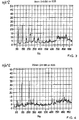
- Figures 3 and 4 are typical graphs of vibrational spectra obtained from the accelerometer 26 measuring the vibration in the direction of the axis of the spindle with two different bits, one being an 8mm diameter bit and the other having a 20mm diameter.
- the vibration spectrum of the hammer using the 8mm diameter bit has a peak 40 at approximately 70 Hz that corresponds to the fundamental vibration, and five further peaks whose intensity generally declines, at 140, 210, 280 340 and 370Hz corresponding to harmonics, above which frequency, no clearly discernible peaks can be seen.
- the intensity of the fundamental vibration is reduced while the second and fourth harmonics at 140 and 270-280 Hz are particularly pronounced.
- vibrational spectra are shown as examples of spectra that can be obtained for a given hammer, but the detail in the spectra will depend on the particular design of hammer.
- Spectra can be obtained for a range of each of the operating parameters, that is to say for a range of drill bit diameters, concrete hardness, and operator bias, and the microprocessor programmed to recognise the particular spectrum, or to recognise characteristics of any spectrum that indicate which of the operating parameters it is based on. The microprocessor then adjusts the relative speed of motors 6 and 8 in order to achieve the optimum rate of penetration.
- One form of hammer has an operation as shown in figure 5.
- a number of sensors are provided for measuring, for example, acceleration in directions both parallel and perpendicular to the tool axis, and optionally instantaneous power consumption and/or operator bias.
- Signals are obtained from the sensors when the hammer is first engaged in the workpiece, and are input to the microprocessor which calculates the operational parameters (bit diameter, concrete hardness and operator bias (if this is not determined by one of the sensors)) therefrom.
- the microprocessor Having determined the operational parameters, the microprocessor then obtains the desired relative speeds for the two motors from a look-up table using the operational parameters as input variables, in order to ascertain the optimum ratio of hammer motor drive speed to rotary motor drive speed, and sets these speeds for the remainder of the drilling operation.
- the microprocessor may repeat the operation every few seconds so that the operational parameters and hence the motor speeds are continually reset during the drilling operation.
- Such an operation has the advantage that variations in the input parameters such as material hardness and operator bias can be accommodated by the hammer
Landscapes
- Engineering & Computer Science (AREA)
- Human Computer Interaction (AREA)
- Manufacturing & Machinery (AREA)
- Physics & Mathematics (AREA)
- General Physics & Mathematics (AREA)
- Automation & Control Theory (AREA)
- Percussive Tools And Related Accessories (AREA)
- Earth Drilling (AREA)
- Ultra Sonic Daignosis Equipment (AREA)
- Percussion Or Vibration Massage (AREA)
- Drilling Tools (AREA)
- Mechanical Pencils And Projecting And Retracting Systems Therefor, And Multi-System Writing Instruments (AREA)
Abstract
Description
- This invention relates to rotary hammers.
- Rotary hammers normally comprise a percussion mechanism for impacting a tool bit that is received by the hammer, for example in a tool holder, and a rotary drive mechanism for rotating the bit. In most cases, a single motor is employed for both mechanisms, with the result that the ratio of the rate of impacts on the tool bit to its rotational speed is always constant. This is not particularly advantageous since in order to optimise the drilling performance, the number of impacts per revolution of the bit will need to be varied depending on a number of operational parameters such as the diameter of the bit, the hardness of the material that is being drilled and the force with which the hammer is applied to the workpiece. GB-A-2,086,777 describes a hammer that includes two motors, one for driving the percussion mechanism and the other for the rotary drive mechanism, so that the relationship between the rotational speed of the tool bit and the frequency of impacts can be selected between wide limits in order to optimise the drilling performance. Such a hammer, however, has the disadvantage that the operator has to calculate and select the appropriate impact per revolution rate depending on the bit size, material etc. which may not be the optimum value, and this value is then set for the entire drilling operation.
- According to the present invention, the hammer includes a sensor for detecting at least one property that is influenced by the operation of the hammer, a processor that determines from the property a number of operational parameters, and determines from the operational parameters the desired ratio of impact rate to rotational speed, and means for setting the impact rate and rotational speed in response to the processor.
- The hammer according to the present invention has the advantage that the operator need not perform any mental process before drilling, but simply engages the hammer in the workpiece, and the appropriate ratio of impact rate to rotational speed of the bit is determined automatically by the hammer.
- The sensor may by any one of a number of sensors that can detect properties of the hammer that are influenced by the operation of the hammer, that is to say, a property that is influenced by the operational parameters of the hammer. For example, the hammer may include a sensor for detecting acceleration in the direction of the axis of rotation of the bit, so that a vibration spectrum may be obtained from the sensor. However, other sensors may be employed instead, for example sensors for detecting instantaneous current consumption in order to detect drilling power and impact power transients.
- The hammer may include more than just a single sensor. For example it may include one or more additional sensors to measure acceleration in a direction perpendicular to the axis of the bit, or it may include a current detector for determining the armature winding current. The hammer may include a sensor for determining the force with which the hammer is applied to the workpiece by the operator or by a mechanism, although in other cases this may be determined by analysis of the vibration spectrum obtained from the accelerometer(s). The signals from the sensors are used by the processor to determine the operational parameters of the drilling operation, for example the diameter of the drill bit being employed, and the hardness of the material forming the workpiece. If desired, the processor may also determine the force with which the hammer is applied to the workpiece (the user bias load) from the vibration spectrum rather than needing a separate sensor for this purpose. The determination of the operational parameters may be performed in a number of ways. This may, for example, be achieved by detecting the amplitude of the fundamental vibrational peak in the vibration spectrum and comparing this with the intensity of the harmonics in the vibration spectrum, and/or measuring the peak width (e.g. at half-height) of the fundamental and/or harmonics, and then employing one or more empirical algorithms obtained from trials to convert the vibrational data to a knowledge of the operational parameters. In some cases, it may be simpler to employ a look-up table to convert vibrational spectra to operational parameters. Once the operational parameters are known, in particular the bit size, material hardness and operator bias load, the appropriate ratio of impact rate to rotational speed can be found. As with determination of the operational parameters, this may be determined either by one or more empirical algorithms or by means of a look-up table based on previous testing. It may, in fact, not be necessary to determine the operational parameters or all of them in order to determine the appropriate number of impacts per revolution, but instead this value may, in some instances, be determined directly from the vibrational spectrum.
- The purpose of setting the ratio of impact rate to rotational speed is to optimise the operation of the hammer, although the particular aspect of operation that is to be optimised may depend on the type of hammer. Thus, in many cases, the ratio of impact rate to rotational speed will be adjusted in order to maximise the rate of penetration of the bit into the workpiece. However, in other cases, it may be desired to minimise the energy consumption of the hammer for any given depth of penetration into the workpiece. This may be of principal importance in the case of battery powered hammers. The value of the actual rate of penetration may be detected, for example, by integrating the signal from the accelerometer (in the direction of the axis of rotation of the bit) over an appropriate time period.
- The hammer according to the invention may be employed in a number of ways. For example, it may be used in an open-loop manner in which the processor receives signals from the sensors in an initial phase of drilling, and determines the optimum ratio of impact rate to rotational speed which is used for the remainder of the drilling operation. Alternatively, the hammer may be used in a closed-loop manner. In this mode of operation, the hammer includes a feedback loop in which the value of the of the quantity to be optimised, for example the ratio of impact rate to rotational speed, is calculated by the microprocessor from values of the other properties such as the acceleration (parallel or perpendicular to the axis of rotation) user bias etc. and the values for the impact rate and rotational speed are fed to the drives for the two motors. The actual values of the properties are measured repeatedly, for example every few seconds, and the speeds of the rotary drive and of the hammer drive motors are then continually adjusted by the microprocessor in response to those values and values of any other input parameters such as user bias. The closed-loop operation has the advantage that the ratio of impact rate to rotational speed can be varied automatically during the drilling operation in response to changed to the operational parameters. For example, the ratio may be changed to take into account variations in material hardness, e.g. where a hard inclusion in the material is hit, or where the material becomes softer, or changes in operator bias load due to operator fatigue.
- The microprocessor may determine the required ratio of impact rate to rotational speed from the measured values of the properties in a number of ways, by inspection of the vibrational spectra. The output of this process is then passed to a look-up table in which the optimum values of the ratio of impact rate to rotational speed for all combinations of the parameters have been stored, in order to obtain values for the relevant motor speed controllers.
- Two forms of hammer in accordance with the present invention will now be described by way of example with reference to the accompanying drawings, in which:
- Figure 1 shows schematically a hammer according to the invention;
- Figure 2 is a graphical representation showing the variation of removal of material as a function of drill bit diameter;
- Figure 3 is a graphical representation of the vibration spectrum of the hammer in the direction of the axis of the bit when a point chisel is employed;
- Figure 4 is a graphical representation of the vibration spectrum of the hammer in the direction of the axis of the bit when a 20 mm drill bit is used;
- Figure 5 is a flow diagram indicating the operation of the hammer.
-
- Referring to the accompanying drawings, figure 1 shows a rotary hammer of the general design shown in GB-A-2,086,777. This form of hammer comprises a housing 1, a
tool holder 2 that can receive atool bit 4, and a pair ofelectric motors 6 and 8. The hammer includes aspindle 10 that supports thetool holder 2 and which can be rotated by means of one motor 6 and a rotary drive mechanism which comprises abevel gear 12 located on the end of thearmature shaft 14 of the motor 6 and anotherbevel gear 16 formed in the rear end of the spindle which meshes therewith. An air-cushion hammer mechanism is shown schematically and comprises acrank 18 driven by thearmature shaft 20 ofmotor 8 which is connected to apiston 22 and causes the piston to slide with reciprocating movement within the spindle. Abeat piece 24 is also located within the spindle and is mechanically connected to thepiston 22 by means of an air cushion formed in the spindle between the piston and the beat piece, so that the beat piece will slide to and fro in the spindle in response to the movement of the piston. The beat piece will hit the rearward end of thetool bit 4 as it moves forward and thereby cause the bit to hit the workpiece with which it is engaged. Because the rotary drive mechanism and the hammer mechanism are driven independently by separate motors, the impact rate of the hammer mechanism on the tool bit, and the rotational speed of the spindle can be varied independently of one another in order to vary the number of impacts per rotation of the bit. - The hammer is modified by the addition of a small
piezoelectric accelerometer 26 that detects vibration in the direction of the axis of the spindle and tool bit, and afurther accelerometer 28 that detects vibration in a direction perpendicular to the axis of the spindle. The output of the accelerometers is fed to a microprocessor (not shown) which controls themotors 6 and 8. - Figure 2 indicates very generally a typical variation of rate of removal of material from a concrete workpiece as a function of bit diameter for a given number of impacts per revolution of the drill bit. For very small drill bits, in this case about 8 to 10 mm, the rate of removal of material is relatively low since, in this region, the impact energy of the hammer is too high for the size of the hole and the rate of formation of the hole is limited by the ability to remove the dust generated from the hole. As the bit diameter is increased, the rate of removal is increased until the optimum relationship is reached between the number of impacts per revolution and bit diameter. If the diameter is increased yet further, the rate of removal of material falls off because, in this region, the impact energy of the hammer is too low or the rotational speed of the bit too high, so that the bit jumps around within the hole that is formed.
- Figures 3 and 4 are typical graphs of vibrational spectra obtained from the
accelerometer 26 measuring the vibration in the direction of the axis of the spindle with two different bits, one being an 8mm diameter bit and the other having a 20mm diameter. The vibration spectrum of the hammer using the 8mm diameter bit has apeak 40 at approximately 70 Hz that corresponds to the fundamental vibration, and five further peaks whose intensity generally declines, at 140, 210, 280 340 and 370Hz corresponding to harmonics, above which frequency, no clearly discernible peaks can be seen. In contrast, in the vibrational spectrum of the hammer using a 20 mm bit, the intensity of the fundamental vibration is reduced while the second and fourth harmonics at 140 and 270-280 Hz are particularly pronounced. These vibrational spectra are shown as examples of spectra that can be obtained for a given hammer, but the detail in the spectra will depend on the particular design of hammer. Spectra can be obtained for a range of each of the operating parameters, that is to say for a range of drill bit diameters, concrete hardness, and operator bias, and the microprocessor programmed to recognise the particular spectrum, or to recognise characteristics of any spectrum that indicate which of the operating parameters it is based on. The microprocessor then adjusts the relative speed ofmotors 6 and 8 in order to achieve the optimum rate of penetration. - One form of hammer has an operation as shown in figure 5. In this open-loop operation, a number of sensors are provided for measuring, for example, acceleration in directions both parallel and perpendicular to the tool axis, and optionally instantaneous power consumption and/or operator bias. Signals are obtained from the sensors when the hammer is first engaged in the workpiece, and are input to the microprocessor which calculates the operational parameters (bit diameter, concrete hardness and operator bias (if this is not determined by one of the sensors)) therefrom. Having determined the operational parameters, the microprocessor then obtains the desired relative speeds for the two motors from a look-up table using the operational parameters as input variables, in order to ascertain the optimum ratio of hammer motor drive speed to rotary motor drive speed, and sets these speeds for the remainder of the drilling operation.
- As an alternative, the microprocessor may repeat the operation every few seconds so that the operational parameters and hence the motor speeds are continually reset during the drilling operation. Such an operation has the advantage that variations in the input parameters such as material hardness and operator bias can be accommodated by the hammer
Claims (12)
- A rotary hammer which comprises a percussion mechanism for impacting a tool bit received by the hammer, and a rotary drive mechanism for rotating the bit, the percussion mechanism and the rotary drive mechanism being variable so that the ratio of rate of impacts on the bit to its rotational speed can be varied, characterised in that the hammer includes a sensor for detecting at least one property that is influenced by the operation of the hammer, a processor that determines from the property a number of operational parameters, and determines from the operational parameters the desired ratio of impact rate to rotational speed, and means for setting the impact rate and rotational speed in response to the processor.
- A hammer as claimed in claim 1, which includes one or more additional sensors.
- A hammer as claimed in claim 1 or claim 2, which includes a sensor for detecting acceleration in the direction of the axis of rotation of the bit.
- A hammer as claimed in claim 2, which includes one or more sensors for detecting acceleration in a direction perpendicular to the axis of rotation of the bit, and/or a sensor for detecting the bias of the operator.
- A hammer as claimed in claim 2, which includes an sensor for measuring the rate of penetration of the hammer into the workpiece.
- A hammer as claimed in any one of claims 1 to 5, which includes a sensor for detecting instantaneous power consumption of the hammer.
- A hammer as claimed in any one of claims 1 to 6, wherein the operational parameters determined by the processor include the material hardness of the workpiece, the diameter of the drill bit, and/or the bias of the operator.
- A hammer as claimed in any one of claims 1 to 7, wherein the processor determines the operational parameters by comparing the intensity of the fundamental vibrational peak to the intensity of harmonics in the vibration spectrum.
- A hammer as claimed in any one of claims 1 to 8, wherein the processor determines the desired ratio of impact rate to rotational speed by means of a look-up table based on experimental data.
- A hammer as claimed in any one of claims 1 to 9, wherein the processor integrates the signal from the acceleration sensor (in the direction of the axis of rotation of the bit) to determine the rate of penetration of bit into the workpiece.
- A hammer as claimed in claim 10, wherein the processor integrates the rate of penetration of the bit into the workpiece to determine the depth of penetration of the bit in the workpiece.
- A hammer as claimed in any one of claims 1 to 10, which includes a feedback loop in which the value of a quantity to be optimised is calculated by the processor from data obtained from the sensor or sensors and used as a set point in the feedback loop, and the actual value of the quantity to be optimised is measured and is subtracted from the set point to obtain an error signal, and the ratio of the impact rate to rotational speed is adjusted by the processor in response to the error signal and data obtained from the sensor or sensors.
Applications Claiming Priority (2)
| Application Number | Priority Date | Filing Date | Title |
|---|---|---|---|
| GBGB0021368.6A GB0021368D0 (en) | 2000-09-01 | 2000-09-01 | Rotary hammer |
| GB0021368 | 2000-09-01 |
Publications (2)
| Publication Number | Publication Date |
|---|---|
| EP1184762A1 true EP1184762A1 (en) | 2002-03-06 |
| EP1184762B1 EP1184762B1 (en) | 2004-06-23 |
Family
ID=9898575
Family Applications (1)
| Application Number | Title | Priority Date | Filing Date |
|---|---|---|---|
| EP01307441A Expired - Lifetime EP1184762B1 (en) | 2000-09-01 | 2001-08-31 | Rotary hammer |
Country Status (6)
| Country | Link |
|---|---|
| EP (1) | EP1184762B1 (en) |
| AT (1) | ATE269982T1 (en) |
| DE (2) | DE10137736A1 (en) |
| ES (1) | ES2218341T3 (en) |
| GB (1) | GB0021368D0 (en) |
| PT (1) | PT1184762E (en) |
Cited By (2)
| Publication number | Priority date | Publication date | Assignee | Title |
|---|---|---|---|---|
| GB2414203A (en) * | 2004-04-14 | 2005-11-23 | Bosch Gmbh Robert | A method for operating a guided machine tool |
| DE102010019651A1 (en) * | 2010-05-06 | 2011-11-10 | Mafell Ag | Electric power tool, particularly chain saw, is drivable by two electromotors in simultaneous manner, where multiple motors are mechanically or electrically switched in parallel or in series |
Families Citing this family (4)
| Publication number | Priority date | Publication date | Assignee | Title |
|---|---|---|---|---|
| DE10309670A1 (en) * | 2003-03-06 | 2004-09-16 | Man Roland Druckmaschinen Ag | Control device for electrical drive of printing machine, calculates load-side slip error from drive-side slip error, torsion angle of drive shaft, load speed etc. |
| DE10318798B4 (en) * | 2003-04-25 | 2006-01-26 | Robert Bosch Gmbh | drill |
| US9102026B2 (en) | 2011-07-13 | 2015-08-11 | Lockheed Martin Corporation | Through hole depth measurement method and device |
| US11819968B2 (en) | 2021-01-19 | 2023-11-21 | Milwaukee Electric Tool Corporation | Rotary power tool |
Citations (4)
| Publication number | Priority date | Publication date | Assignee | Title |
|---|---|---|---|---|
| US4157231A (en) * | 1977-09-27 | 1979-06-05 | The United States Of America As Represented By The Secretary Of The Air Force | Hydraulic drill unit |
| GB2086777A (en) * | 1980-11-06 | 1982-05-19 | Hilti Ag | Percussion drilling machine |
| US4688970A (en) * | 1985-08-09 | 1987-08-25 | Dresser Industries, Inc. | Power drill and automatic control system therefore |
| US5755537A (en) * | 1993-11-23 | 1998-05-26 | Johannes Lubbering Ag | Portable precision drill |
-
2000
- 2000-09-01 GB GBGB0021368.6A patent/GB0021368D0/en not_active Ceased
-
2001
- 2001-08-01 DE DE10137736A patent/DE10137736A1/en not_active Ceased
- 2001-08-31 EP EP01307441A patent/EP1184762B1/en not_active Expired - Lifetime
- 2001-08-31 AT AT01307441T patent/ATE269982T1/en not_active IP Right Cessation
- 2001-08-31 ES ES01307441T patent/ES2218341T3/en not_active Expired - Lifetime
- 2001-08-31 PT PT01307441T patent/PT1184762E/en unknown
- 2001-08-31 DE DE60103956T patent/DE60103956T2/en not_active Expired - Lifetime
Patent Citations (4)
| Publication number | Priority date | Publication date | Assignee | Title |
|---|---|---|---|---|
| US4157231A (en) * | 1977-09-27 | 1979-06-05 | The United States Of America As Represented By The Secretary Of The Air Force | Hydraulic drill unit |
| GB2086777A (en) * | 1980-11-06 | 1982-05-19 | Hilti Ag | Percussion drilling machine |
| US4688970A (en) * | 1985-08-09 | 1987-08-25 | Dresser Industries, Inc. | Power drill and automatic control system therefore |
| US5755537A (en) * | 1993-11-23 | 1998-05-26 | Johannes Lubbering Ag | Portable precision drill |
Cited By (3)
| Publication number | Priority date | Publication date | Assignee | Title |
|---|---|---|---|---|
| GB2414203A (en) * | 2004-04-14 | 2005-11-23 | Bosch Gmbh Robert | A method for operating a guided machine tool |
| GB2414203B (en) * | 2004-04-14 | 2006-05-31 | Bosch Gmbh Robert | Guided machine tool and method for operating a guided machine tool |
| DE102010019651A1 (en) * | 2010-05-06 | 2011-11-10 | Mafell Ag | Electric power tool, particularly chain saw, is drivable by two electromotors in simultaneous manner, where multiple motors are mechanically or electrically switched in parallel or in series |
Also Published As
| Publication number | Publication date |
|---|---|
| DE10137736A1 (en) | 2002-04-04 |
| EP1184762B1 (en) | 2004-06-23 |
| DE60103956D1 (en) | 2004-07-29 |
| GB0021368D0 (en) | 2000-10-18 |
| ATE269982T1 (en) | 2004-07-15 |
| ES2218341T3 (en) | 2004-11-16 |
| DE60103956T2 (en) | 2005-06-30 |
| PT1184762E (en) | 2004-10-29 |
Similar Documents
| Publication | Publication Date | Title |
|---|---|---|
| US20090195204A1 (en) | Power Tool Having Motor Speed Monitor | |
| US6044918A (en) | Percussion blow added manually operable drilling tool | |
| EP2239099B1 (en) | Electric power tool and motor control method thereof | |
| CN107000186B (en) | Safety method and hand-held power tool | |
| JP4211744B2 (en) | Impact tightening tool | |
| US10688614B2 (en) | Portable power tool | |
| USRE44993E1 (en) | Power tool anti-kickback system with rotational rate sensor | |
| EP2279831B1 (en) | Vibration damping system for a power tool and in particular for a powered hammer | |
| EP1207016B1 (en) | Impact power tools | |
| US9579783B2 (en) | Power tool having improved operability | |
| US10556333B2 (en) | Machine-tool device | |
| US6799644B2 (en) | Pneumatic percussive mechanism | |
| US20130037288A1 (en) | Control Scheme For Detecting And Preventing Torque Conditions In A Power Tool | |
| CN114502327B (en) | Method for identifying the progress of work on a handheld machine tool | |
| CN104428106A (en) | Impact Mechanism Unit | |
| US6854529B2 (en) | Optimizing method for regulating the operating state of a guided machine tool comprising a rotating percussion tool during a boring process | |
| CN107000187A (en) | Control method for hand held power machine | |
| EP1184762B1 (en) | Rotary hammer | |
| US7870910B2 (en) | Vibration generator for a vibration pile driver | |
| CN106457541A (en) | Hand-held power tool and control method | |
| JP6391323B2 (en) | Hand-held machine tool | |
| US20210316435A1 (en) | Hand-Held Power Tool and Method for Operating a Hand-Held Power Tool | |
| JP6927296B2 (en) | Strike work machine | |
| RU2000104157A (en) | METHOD FOR DETERMINING ROCK STRENGTH AND DEVICE FOR ITS IMPLEMENTATION (OPTIONS) |
Legal Events
| Date | Code | Title | Description |
|---|---|---|---|
| PUAI | Public reference made under article 153(3) epc to a published international application that has entered the european phase |
Free format text: ORIGINAL CODE: 0009012 |
|
| AK | Designated contracting states |
Kind code of ref document: A1 Designated state(s): AT BE CH CY DE DK ES FI FR GB GR IE IT LI LU MC NL PT SE TR |
|
| AX | Request for extension of the european patent |
Free format text: AL;LT;LV;MK;RO;SI |
|
| 17P | Request for examination filed |
Effective date: 20020819 |
|
| AKX | Designation fees paid |
Free format text: AT BE CH CY DE DK ES FI FR GB GR IE IT LI LU MC NL PT SE TR |
|
| 17Q | First examination report despatched |
Effective date: 20030324 |
|
| GRAP | Despatch of communication of intention to grant a patent |
Free format text: ORIGINAL CODE: EPIDOSNIGR1 |
|
| GRAS | Grant fee paid |
Free format text: ORIGINAL CODE: EPIDOSNIGR3 |
|
| GRAA | (expected) grant |
Free format text: ORIGINAL CODE: 0009210 |
|
| AK | Designated contracting states |
Kind code of ref document: B1 Designated state(s): AT BE CH CY DE DK ES FI FR GB GR IE IT LI LU MC NL PT SE TR |
|
| PG25 | Lapsed in a contracting state [announced via postgrant information from national office to epo] |
Ref country code: CH Free format text: LAPSE BECAUSE OF FAILURE TO SUBMIT A TRANSLATION OF THE DESCRIPTION OR TO PAY THE FEE WITHIN THE PRESCRIBED TIME-LIMIT Effective date: 20040623 Ref country code: LI Free format text: LAPSE BECAUSE OF FAILURE TO SUBMIT A TRANSLATION OF THE DESCRIPTION OR TO PAY THE FEE WITHIN THE PRESCRIBED TIME-LIMIT Effective date: 20040623 Ref country code: FI Free format text: LAPSE BECAUSE OF FAILURE TO SUBMIT A TRANSLATION OF THE DESCRIPTION OR TO PAY THE FEE WITHIN THE PRESCRIBED TIME-LIMIT Effective date: 20040623 Ref country code: NL Free format text: LAPSE BECAUSE OF FAILURE TO SUBMIT A TRANSLATION OF THE DESCRIPTION OR TO PAY THE FEE WITHIN THE PRESCRIBED TIME-LIMIT Effective date: 20040623 Ref country code: CY Free format text: LAPSE BECAUSE OF FAILURE TO SUBMIT A TRANSLATION OF THE DESCRIPTION OR TO PAY THE FEE WITHIN THE PRESCRIBED TIME-LIMIT Effective date: 20040623 Ref country code: TR Free format text: LAPSE BECAUSE OF FAILURE TO SUBMIT A TRANSLATION OF THE DESCRIPTION OR TO PAY THE FEE WITHIN THE PRESCRIBED TIME-LIMIT Effective date: 20040623 Ref country code: AT Free format text: LAPSE BECAUSE OF FAILURE TO SUBMIT A TRANSLATION OF THE DESCRIPTION OR TO PAY THE FEE WITHIN THE PRESCRIBED TIME-LIMIT Effective date: 20040623 |
|
| REG | Reference to a national code |
Ref country code: GB Ref legal event code: FG4D |
|
| REG | Reference to a national code |
Ref country code: CH Ref legal event code: EP |
|
| REG | Reference to a national code |
Ref country code: SE Ref legal event code: TRGR |
|
| REG | Reference to a national code |
Ref country code: IE Ref legal event code: FG4D |
|
| REF | Corresponds to: |
Ref document number: 60103956 Country of ref document: DE Date of ref document: 20040729 Kind code of ref document: P |
|
| PG25 | Lapsed in a contracting state [announced via postgrant information from national office to epo] |
Ref country code: LU Free format text: LAPSE BECAUSE OF NON-PAYMENT OF DUE FEES Effective date: 20040831 Ref country code: MC Free format text: LAPSE BECAUSE OF NON-PAYMENT OF DUE FEES Effective date: 20040831 Ref country code: IE Free format text: LAPSE BECAUSE OF NON-PAYMENT OF DUE FEES Effective date: 20040831 |
|
| PG25 | Lapsed in a contracting state [announced via postgrant information from national office to epo] |
Ref country code: GR Free format text: LAPSE BECAUSE OF FAILURE TO SUBMIT A TRANSLATION OF THE DESCRIPTION OR TO PAY THE FEE WITHIN THE PRESCRIBED TIME-LIMIT Effective date: 20040923 Ref country code: DK Free format text: LAPSE BECAUSE OF FAILURE TO SUBMIT A TRANSLATION OF THE DESCRIPTION OR TO PAY THE FEE WITHIN THE PRESCRIBED TIME-LIMIT Effective date: 20040923 |
|
| REG | Reference to a national code |
Ref country code: PT Ref legal event code: SC4A Free format text: AVAILABILITY OF NATIONAL TRANSLATION Effective date: 20040908 |
|
| REG | Reference to a national code |
Ref country code: ES Ref legal event code: FG2A Ref document number: 2218341 Country of ref document: ES Kind code of ref document: T3 |
|
| NLV1 | Nl: lapsed or annulled due to failure to fulfill the requirements of art. 29p and 29m of the patents act | ||
| REG | Reference to a national code |
Ref country code: CH Ref legal event code: PL |
|
| ET | Fr: translation filed | ||
| PLBE | No opposition filed within time limit |
Free format text: ORIGINAL CODE: 0009261 |
|
| STAA | Information on the status of an ep patent application or granted ep patent |
Free format text: STATUS: NO OPPOSITION FILED WITHIN TIME LIMIT |
|
| REG | Reference to a national code |
Ref country code: IE Ref legal event code: MM4A |
|
| 26N | No opposition filed |
Effective date: 20050324 |
|
| PGFP | Annual fee paid to national office [announced via postgrant information from national office to epo] |
Ref country code: ES Payment date: 20070827 Year of fee payment: 7 |
|
| PGFP | Annual fee paid to national office [announced via postgrant information from national office to epo] |
Ref country code: SE Payment date: 20070829 Year of fee payment: 7 |
|
| PGFP | Annual fee paid to national office [announced via postgrant information from national office to epo] |
Ref country code: BE Payment date: 20071003 Year of fee payment: 7 |
|
| PGFP | Annual fee paid to national office [announced via postgrant information from national office to epo] |
Ref country code: FR Payment date: 20080818 Year of fee payment: 8 |
|
| REG | Reference to a national code |
Ref country code: PT Ref legal event code: MM4A Free format text: LAPSE DUE TO NON-PAYMENT OF FEES Effective date: 20090302 |
|
| PG25 | Lapsed in a contracting state [announced via postgrant information from national office to epo] |
Ref country code: PT Free format text: LAPSE BECAUSE OF NON-PAYMENT OF DUE FEES Effective date: 20090302 |
|
| PG25 | Lapsed in a contracting state [announced via postgrant information from national office to epo] |
Ref country code: BE Free format text: LAPSE BECAUSE OF NON-PAYMENT OF DUE FEES Effective date: 20080831 |
|
| REG | Reference to a national code |
Ref country code: ES Ref legal event code: FD2A Effective date: 20080901 |
|
| PGFP | Annual fee paid to national office [announced via postgrant information from national office to epo] |
Ref country code: PT Payment date: 20070731 Year of fee payment: 7 |
|
| PG25 | Lapsed in a contracting state [announced via postgrant information from national office to epo] |
Ref country code: ES Free format text: LAPSE BECAUSE OF NON-PAYMENT OF DUE FEES Effective date: 20080901 |
|
| REG | Reference to a national code |
Ref country code: FR Ref legal event code: ST Effective date: 20100430 |
|
| PG25 | Lapsed in a contracting state [announced via postgrant information from national office to epo] |
Ref country code: FR Free format text: LAPSE BECAUSE OF NON-PAYMENT OF DUE FEES Effective date: 20090831 Ref country code: SE Free format text: LAPSE BECAUSE OF NON-PAYMENT OF DUE FEES Effective date: 20080901 |
|
| PGFP | Annual fee paid to national office [announced via postgrant information from national office to epo] |
Ref country code: GB Payment date: 20110825 Year of fee payment: 11 |
|
| PGFP | Annual fee paid to national office [announced via postgrant information from national office to epo] |
Ref country code: IT Payment date: 20110824 Year of fee payment: 11 |
|
| GBPC | Gb: european patent ceased through non-payment of renewal fee |
Effective date: 20120831 |
|
| PG25 | Lapsed in a contracting state [announced via postgrant information from national office to epo] |
Ref country code: IT Free format text: LAPSE BECAUSE OF NON-PAYMENT OF DUE FEES Effective date: 20120831 |
|
| PG25 | Lapsed in a contracting state [announced via postgrant information from national office to epo] |
Ref country code: GB Free format text: LAPSE BECAUSE OF NON-PAYMENT OF DUE FEES Effective date: 20120831 |
|
| PGFP | Annual fee paid to national office [announced via postgrant information from national office to epo] |
Ref country code: DE Payment date: 20150827 Year of fee payment: 15 |
|
| REG | Reference to a national code |
Ref country code: DE Ref legal event code: R119 Ref document number: 60103956 Country of ref document: DE |
|
| PG25 | Lapsed in a contracting state [announced via postgrant information from national office to epo] |
Ref country code: DE Free format text: LAPSE BECAUSE OF NON-PAYMENT OF DUE FEES Effective date: 20170301 |