TECHNICAL FIELD
-
The present invention relates to an oil application device
as a component of a fixing device of an electrostatic process
copying machine, an electrophotographic printer or the like.
BACKGROUND ART
-
In a fixing device of an electronic copying machine, an
electronic printing machine or the like, during fixation of
toner that has been transferred to a recording paper, the
toner may adhere to a thermal fixing roller. To prevent the
toner from soiling another, recording paper, a very small
amount of releasing oil such as silicon oil is applied to the
thermal fixing roll using an oil application roller. Thus,
toner is prevented from adhering to the thermal fixing roll,
and recording papers are prevented from being stuck to one
another and rolled up.
-
Various oil application rollers having such a function have
already been proposed. For example, a cylindrical formed
body made from a perforated metal hollow pipe and heat-resistant
fiber is used as an oil retaining member for
storing releasing oil to be applied, and an oil application
amount control layer e.g. made from a polytetrafluoroethylene
(PTFE) porous film is wound around the surface of the
cylindrical formed body. Ends and wrapping portions of the
oil application amount control layer are coated with RTV
silicon rubber and bonded, so that an oil application roller
is manufactured. Further, there is another oil application
roller, which is manufactured by processing the oil
application amount control layer as described above into a
tube, covering a cylindrical oil retaining member with the
tube, and heating and contracting them (see Japanese Patent
Application Laid-Open No. HEI 9-185282).
-
Further, there is an application mechanism for copying
machines, which is provided with an oil application amount
control layer that has been formed through cross linkage
after impregnation of voids of porous polytetrafluorethylene
of the surface of a thick porous material as an oil retaining
member with the mixture of silicon rubber and releasing oil
(Japanese Published Patent No. HEI 6-73051). That is, this
application mechanism for copying machines is obtained by
winding an oil application amount control layer around the
surface of the thick porous material like a rolled laver,
heating them at a high temperature for many hours to cause
cross linkage, and thermally fusing them. This application
mechanism for copying machines can suitably control releasing
oil, i.e., silicon oil, and especially can stably control it
over a long time even in an area where a very small amount of
silicon oil is applied for oilless toner. Further, Japanese
Patent Application Laid-Open No. 2000-79365 discloses an oil
application device in which a felt layer is disposed on a
surface of a cylindrical oil retaining member made from
porous ceramics material and in which a PTFE porous film is
disposed on the felt layer. This oil application device
applies oil that has exuded to the felt from the oil
retaining member, while controlling the oil by means of the
porous film. Further, the oil application device may not
necessarily be of a roller type. For example, there is known
an oil application device in which oil is applied to a fixing
roll by a generally flat pad.
-
However, in the above-mentioned oil application roller in
which the oil application amount control layer is bonded with
the cylindrical formed body, almost no releasing oil flows
out of the bonded portion so that oil is applied unevenly, or
the bonding strength is insufficient due to a small bonded
area so that the oil application amount control layer is
displaced or peels off. That is, it is difficult to always
stably apply releasing oil to the thermal fixing roll.
Further, in the oil application roller manufactured by
heating and contracting the tubular oil application amount
control layer, the oil application amount control layer tends
to be heated and contracted inhomogeneously, and the pore
diameter is inconsistent. That is, it is difficult to always
stably apply releasing oil to the thermal fixing roll.
Furthermore, in the application mechanism for copying
machines, when the oil application amount control layer is
thermally fused with the thick porous material, heating must
be carried out for a long time at a high temperature. Thus,
the process tends to be too troublesome. Further, in the
application device that applies oil that has exuded to the
felt from the oil retaining member while controlling the oil
by means of the porous film or in the application device that
applies oil to the fixing roll by means of a pad-like
structure, the same problem as described above arises as to a
method of bonding the oil application amount control layer to
the top surface layer. Namely, also in this case, no
releasing oil flows out of the bonded portion so that
unevenness of application is caused, or the bonding strength
is insufficient due to a small bonded area so that the oil
application amount control layer is displaced or peels off.
This leads to a problem of fluctuations of application amount
of oil. Furthermore, in a so-called inoperative state other
than application, e.g., in a state from shipment to
preservation of products, it is also required that oil in the
oil retaining member be prevented from exuding from the oil
application amount control layer. Such exudation of oil
causes a problem of excessive application of oil at the
beginning of an application process when restarting the
application device.
-
It is thus an object of the present invention to provide an
oil application device in which releasing oil can be
uniformly applied to a thermal fixing roll, in which an oil
application amount control layer is not displaced or does not
peel off during operation, and which can be bonded with an
oil retaining member easily. It is another object of the
present invention to provide an oil application device in
which no oil exudes from an oil application amount control
layer e.g. in a still-standing state from shipment to
preservation of products.
DISCLOSURE OF THE INVENTION
-
Under such circumstances, the inventors discovered the
following facts as a result of careful and detailed
researches and succeeded in completing the invention. That
is, if an oil application amount control layer is bonded with
an oil retaining member for retaining application-use silicon
oil by means of the mixture of adhesive and mixture-use
silicon oil, the mixture is in a state of dispersal of the
adhesive and the mixture-use silicon oil. Thus, the oil
application amount control layer is bonded with the oil
retaining member due to the hardening of the adhesive. In
the oil application amount control layer, closed-pore
portions and unclosed-pore portions with interposition of the
unhardened mixture-use silicon oil are dispersed through each
other. This bonded portion in a state of dispersal prevents
the oil application amount control layer from being displaced
or peeling off, and the mixture-use silicon oil in its
dispersed state serves as an oil passage and makes it
possible to uniformly apply application-use silicon oil to a
thermal fixing roll. If the ratio of the viscosity of
application-use silicon oil to the viscosity of mixture-use
silicon oil is in a certain range, i.e., if the viscosity of
application-use silicon oil is relatively close to the
viscosity of mixture-use silicon oil, no oil exudes from the
oil application amount control layer in a still-standing
state.
-
That is, the first invention of the present invention
provides an oil application device wherein an oil application
amount control layer is bonded with an oil retaining member
for retaining application-use silicon oil, using the mixture
of adhesive and mixture-use silicon oil, and wherein the
ratio (VKS)/(VTS) of a viscosity (VKS) of the mixture-use
silicon oil at 25°C to a viscosity (VTS) of the application-use
silicon oil at 25°C ranges from 50/1 to 1/10. According
to this construction, the oil retaining member and the oil
application amount control layer are bonded together while
being dispersed as a whole due to the hardening of the
dispersed adhesive, and the oil application amount control
layer guarantees a passage for the application-use silicon
oil while being dispersed as a whole due to the dispersed
mixture-use silicon oil. Further, since diffusion
(infiltration) of the application-use silicon oil into the
mixture-use silicon oil existing as an oil passage is
suppressed in a still-standing state, no silicon oil exudes
to the surface of the oil application amount control layer.
-
Further, the second invention of the present invention
provides an oil application device wherein an oil application
amount control layer is bonded with an oil transfer layer
that is provided on an oil-application side of an oil
retaining member for retaining application-use silicon oil,
using the mixture of adhesive and mixture-use silicon oil,
and wherein the ratio (VKS)/(VTS) of a viscosity (VKS) of the
mixture-use silicon oil at 25°C to a viscosity (VTS) of the
application-use silicon oil at 25°C ranges from 50/1 to 1/10.
According to this construction, even in the case where the
oil transfer layer for preventing uneven application is
provided between the oil retaining member and the oil
application amount control layer, the same effect as
described above can substantially be achieved.
-
Further, the third invention of the present invention
provides an oil application device wherein the viscosity
(VKS) of the mixture-use silicon oil at 25°C is equal to the
viscosity (VTS) of the application-use silicon oil at 25°C.
According to this construction, diffusion (infiltration) of
the application-use silicon oil into the mixture-use silicon
oil is further suppressed, not to mention that the same
effect as described above can substantially be achieved
during nonuse. Therefore, it is possible to reliably prevent
silicon oil from exuding to the surface of the oil
application amount control layer.
BRIEF DESCRIPTION OF THE DRAWINGS
-
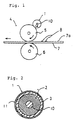
Fig. 1 is a side view showing how an oil application device
according to an embodiment of the present invention is
installed in a fixing device. Fig. 2 is a radial cross-sectional
view of the oil application device according to the
embodiment of the present invention.
DETAILED DESCRIPTION
-
Hereinafter, an oil application device according to an
embodiment of the present invention will be described in
detail with reference to Figs. 1 and 2. Fig. 1 is a side
view showing how the oil application device according to the
embodiment of the present invention is installed in a fixing
device. Fig. 2 is a radial cross-sectional view of the oil
application device according to the embodiment of the present
invention. In the drawings, the oil application device is
denoted by reference numeral 1. The oil application device 1
is basically composed of an oil retaining member 2 and an oil
application amount control layer 3, which are bonded together
by the mixture of adhesive and mixture-use silicon oil. The
oil application device 1 is built into a fixing device 4,
which allows a recording paper 7 to pass through a space
between a thermal fixing roll 5 and a press roll 6 so that
toner 8 transferred to a surface 7a of the recording paper 7
will be fixed. In order to prevent the toner 8 on the
surface 7a of the recording paper 7 from adhering to the
thermal fixing roll 5, the oil application device 1 is
opposed to and in contact with the thermal fixing roll 5 so
as to apply releasing oil, i.e., application-use silicon oil
to the thermal fixing roll 5.
-
The dil retaining member 2 is not specifically limited as
long as it has a structure capable of retaining application-use
silicon oil. For instance, the oil retaining member 2 of
this embodiment is a cylindrical porous formed body for
retaining a large amount of application-use silicon oil in a
large-capacity agglomerate of pores with a pore diameter of
50 to 2000µm and a volume porosity of 60 to 80%. The oil
retaining member 2 is fitted with a shaft 10. Due to
capillarity, the retained application-use silicon oil is
transferred to an oil transfer layer, i.e., a heat-resistant
felt 11 via minute inter-fiber gaps, then infiltrates into
the oil application amount control layer 3 made of a porous
film, and finally exudes to the surface of the oil
application amount control layer 3. The application-use
silicon oil used in this embodiment has a low viscosity(VTS),
which is usually 10×10-6 to 500×10-6m2/seconds (10 to 500cSt)
and preferably 50×10-6 to 300×10-6m2/seconds (10 to 300cSt) at
a temperature of 25°C. Although the oil retaining member 2
is preferably a porous ceramic formed body, it should not be
limited to the formed body of the above-mentioned structure.
Namely, it is possible to use a great variety of porous
materials including a spongy material, a material with a pore
diameter of less than 50µm, etc. Because releasing oil is
retained in the large pores and because the inter-fiber gaps
allow the releasing oil to be transferred due to capillary,
the oil retaining member 2 can achieve high oil-retaining
performance and age-resistant oil application performance.
-
A porous-ceramic oil retaining member can be manufactured
as follows. That is, one or more ceramic fibers selected
from silica fiber, silica alumina fiber, alumina fiber and
glass fiber, one or more kinds of ceramic particles that are
selected from silica particles, silica alumina particles,
alumina particles and glass particles and that are blended if
necessary, one or more inorganic binders selected from silica
sol, alumina sol and glass frit, particles of organic resins
such as polypropylene, an organic binder, and water are used
as raw materials. These kneaded raw materials are formed
into a formed body of a predetermined shape e.g. by extrusion.
Then, the formed body is dried and calcined to obtain the
porous-ceramic oil retaining member. The ceramic fibers to
be selected have a fiber diameter of 2 to 30µm and a fiber
length of 100 to 5000µm. The ceramic particles to be
selected have a particle diameter of 10 to 50µm. The organic
resin particles to be used have a particle diameter of 200 to
2000µm.
-
The above porous ceramic material is provided with a porous
structure through gasification of organic binder, water and
organic resin particles at the time of calcination. More
specifically, inter-fiber gaps with a main pore diameter of
10 to 100µm are formed through gasification of organic binder
and water, and large pores with a diameter of 200 to 2000µm
are obtained through gasification of organic resin particles.
In this porous ceramic material, the large pores serve to
store up silicon oil and the inter-fiber gaps serve to
transfer silicon oil by means of capillarity.
-
An oil transfer layer 11 is formed on an outer periphery of
the oil retaining member 2. The oil transfer layer 11 can be
made from a heat-resistant fiber felt. For example, this
heat-resistant fiber felt is obtained by forming a group of
fiber materials into a sheet web by roller forming or the
like and then processing it by needle punching. The heat-resistant
fiber felt is composed of a fiber material with a
diameter of approximately 10µm and has a three-dimensional
flexible network structure with a weight of 200 to 800g/m2, a
thickness of 1 to 5mm, and a density of 170 to 260kg/m3. The
oil transfer layer 11 may be a lamination of different kinds
of layers. By disposing the oil transfer layer 11 on the
outer periphery of the oil retaining member 2, the oil
application device 1 can ensure a certain contact area in
supplying releasing oil while being in contact with the
fixing roller 5 and guarantee uniform application of a
predetermined amount of releasing oil. A method of disposing
the oil transfer layer 11 on the oil retaining member 2 is
not specifically limited. For example, it is possible to
adopt a method of winding a felt around the oil retaining
member 2 and fixing it thereto e.g. by means of adhesives or
pressure fittings, a method of carrying out fixation based on
adhesion to a later-described PTFE film, and so on.
According to one example of such methods, RTV rubber is
applied to the edges of a felt that has been cut into the
shape of a ribbon with a width of approximately 30mm, and the
felt is brought into abutment on the oil retaining member 2
with the edges not overlapping with one another, and is
spirally wound around the oil retaining member 2.
-
The oil application amount control layer 3 has a gas
permeability of 10 to 2000seconds/100cc and is not
specifically limited as long as silicon oil can permeate
therethrough. A stretched polytetrafluoroethylene (PTFE)
porous film (hereinafter referred to as the PTFE porous film)
is used as the oil application amount control layer 3 of this
embodiment. For example, the PTFE porous film has a surface
roughness Ra of 0.7 to 0.8mm, a thickness of 50 to 100µm, a
gas permeability of 60 to 100seconds/100cc, an open pore
diameter of 0.05 to 2.0µm and an open porosity of 70 to 90%.
Note that the "gas permeability" is a Gurley's number (unit:
seconds/100cc) measured by a B-type Gurley densometer and
that the "open porosity" is calculated from measured specific
gravities according to the following equation: open porosity
(%) = (1-bulk specific gravity/absolute specific gravity) ×
100.
-
The oil application amount control layer 3 is bonded with
the oil transfer layer 11 formed on the outer periphery of
the oil retaining member 2 using the mixture of adhesive and
mixture-use silicon oil. It is important that adhesive and
mixture-use silicon oil be mixed sufficiently and dispersed
through each other in the mixture. Although bonding may
occur either partially or entirely, entire bonding is
preferred because it can enhance bonding strength of the oil
application amount control layer 3 and thus achieve higher
reliability. For example, in the case of entire bonding, the
mixture is applied to the back (bonded surface) of the oil
application amount control layer 3 with a density of 50 to
250g/m2, and the back of the oil application amount control
layer 3 is stuck to the oil transfer layer 11 and then dried
for one to four hours until the adhesive components are
solidified. Thus, since the solidified adhesive components
exist in some of the open pores while being dispersed into
mixture-use silicon oil, strength and durability of the
porous film can further be enhanced. On the other hand, from
a microscopic point of view, since adhesive is dispersed into
mixture-use silicon oil in the mixture of adhesive and
mixture-use silicon oil, the area of silicon oil serves as a
passage for releasing oil in the open pores. Accordingly,
the open pores of the porous film are filled with the mixture,
whereby a passage for releasing oil is guaranteed despite
closure of the open pores. Thus, a suitable amount of
releasing oil can be applied, and the amount of application
can be controlled.
-
The adhesive is not specifically limited as long as it can
bond the oil transfer layer 11 with the oil application
amount control layer 3 in the presence of mixture-use silicon
oil. For example, silicon varnish is used as the adhesive.
What is generally called silicon varnish can be used as
silicon varnish. For example, silicon resin is obtained by
excessively increasing a cross-link density of silicon rubber,
and silicon varnish is obtained by dissolving unreacted
silicon resin into a solvent. This silicon varnish has many
3- to 4-functional components and is superior in bonding
performance to silicon rubber. Silicon varnish has a
viscosity of 10×10-6 to 200000×10-6m2/seconds (10 to
200000cSt) at a temperature of 25°C, and preferably of
500×10-6 to 100000×10-6m2/seconds (500 to 100000cSt) at a
temperature of 25°C. Note that the term "viscosity" in the
present specification means a viscosity at a temperature of
25°C unless otherwise specified.
-
Concrete examples of mixture-use silicon oil, which is to
be mixed with silicon varnish, include straight-chain methyl
silicon oil, bifurcated methyl silicon oil, methyl phenyl
silicon oil and modified silicon oil that has some of its
dimethyl groups replaced by other organic groups. The
mixture-use silicon oil usually has a viscosity (VKS) of
1×10⁻⁶ to 25000×10-6m2/seconds (1 to 25000cSt), and preferably
of (50)×10-6 to (3000)×10-6m2/seconds (50 to 3000cSt), more
preferably of (50)×10-6 to (300)×10-6m2/seconds (50 to 300cSt).
-
In the present invention, the ratio (VKS)/(VTS) of the
viscosity of mixture-use silicon oil (VKS) to the viscosity
of application-use silicon oil (VTS) ranges from 50/1 to 1/10,
and preferably ranges from 5/1 to 1/2, and most preferably is
equal to 1/1. If the viscosity (VKS) of mixture-use silicon
oil is fifty or more times as high as the viscosity (VTS) of
application-use silicon oil, i.e., has too high a degree of
polymerization, low-viscosity application-use silicon oil is
diffused (infiltrated) into high-viscosity mixture-use
silicon oil via a porous member such as the oil retaining
member or in the porous member. In addition, due to a
capillarity-based moving force applied from the oil retaining
member to the PTFE film in the felt layer, the concentration
of silicon oil (the mixture of application-use silicon oil
and mixture-use silicon oil) is increased in the vicinity of
an interface between the felt layer and the PTFE film. As a
result, in a still-standing state, part of the silicon oil
exudes to the surface of the PTFE film. However, if the
viscosity of mixture-use silicon oil and the viscosity of
application-use silicon oil satisfy the above-mentioned
relationship, the phenomenon of diffusion of application-use
silicon oil into mixture-use silicon oil is suppressed. Thus,
in a still-standing state, no silicon oil exudes to the
surface of the PTFE film.
-
The mixture ratio (SW:SO) of silicon varnish (SW) to
mixture-use silicon oil (SO) ranges from 10:90 to 90:10. If
the amount of silicon varnish is too large, the adhesive area
is large and the passage for silicon oil is narrow, which
results in an insufficient amount of application. On the
contrary, if the amount of mixture-use silicon oil is too
large, the adhesive area is small and the bonding strength,
especially the initial bonding strength between the oil
transfer layer 11 and the oil application amount control
layer 3 is insufficient. Further, the mixture of silicon
varnish and mixture-use silicon oil has a viscosity of e.g.
100×10-6 to 180000×10-6m2/seconds (100 to 180000cSt), and
preferably of 200×10-6 to 50000×10-6m2/seconds (200 to
50000cSt). If the viscosity of the mixture is too low, the
initial bonding strength in bonding the oil application
amount control layer 3 with the oil transfer layer 11 is
small. As a result, immediately after application of the
mixture to the oil application amount control layer 3, the
mixture flows out of the open pores in the oil application
amount control layer 3. On the other hand, if the viscosity
of the mixture is too high, the open pores in the oil
application amount control layer 3 is unlikely to be filled
with the mixture, and it is difficult to achieve a sufficient
bonding strength.
-
In the present invention, although either the oil retaining
member and the oil application amount control layer or the
oil transfer layer and the oil application amount control
layer are bonded together by the above-mentioned mixture, the
adhesive layer may or may not manifest itself. For example,
the PTFE film and the felt layer are bonded together, and as
a result of infiltration of the above-mentioned mixture into
the PTFE film and the felt layer, an adhesive-coated layer
irrelévant to bonding may be formed.
-
Although the roller-type oil application device has been
described as an example of this embodiment, the present
invention is not limited thereto. The present invention is
widely applicable to oil application devices for applying
releasing oil while being in contact with a member to which
oil is to be applied, e.g., planar or linear oil application
devices. The oil application device of the present invention
applies a very small amount of releasing oil such as silicon
oil to a thermal fixing roll of an electronic copying machine,
an electronic printing machine or the like, and thus can
prevent toner from adhering to the thermal fixing roll.
(Examples)
-
Next, the present invention will be described in more
detail referring to examples, which are not intended to limit
the present invention.
Example 1
-
50 parts by weight of silica alumina fiber with a fiber
diameter of 5µm and a fiber length of 2500µm, 20 parts by
weight of polyethylene resin powders with a particle diameter
of 300µm, 10 parts by weight of silica sol, 10 parts by
weight of methyl cellulose as an organic binder, and 50 parts
by weight of water were kneaded. By extruding these kneaded
materials, a cylindrical formed body with a length of 300mm
and a diameter of 33mm was obtained. Next, this cylindrical
formed body was dried for two hours at 120°C and then
calcined for eight hours at 480°C. Inter-fiber gaps with a
main diameter distribution of 10 to 100µm were formed through
gasification of water and the organic binder in this process.
Further, a porous-ceramic oil retaining member having large
pores with a diameter of 300µm was obtained through burnout
of resin particles. Next, an oil transfer layer was provided
on an application side of the porous-ceramic oil retaining
member. The oil transfer layer was fixed to the oil
retaining member by applying RTV silicon rubber to edges of a
heat-resistant fiber felt in the shape of a ribbon with a
thickness of 2mm, a weight of 500g/m2 and a width of 30mm,
and spirally winding the felt around the oil retaining member
with the adjacent edges abutting on each other.
-
Then, a PTFE porous film as the oil application amount
control layer was provided on an application side of the oil
transfer layer. The PTFE porous film was bonded using the
mixture obtained by mixing silicon oil (manufactured by
Shinetsu Chemical Industry Corporation: KF-96-100) with a
viscosity of 100×10-6m2/seconds (100cSt) with silicon varnish
(manufactured by Shinetsu Chemical Industry Corporation: KR-105)
with a viscosity of 700×10-6m2/seconds (700cSt) at a
ratio of 20:80 (weight ratio). The viscosity of the mixture
was approximately 450×10-6m2/seconds (450cSt). The bonding of
the PTFE porous film was carried out by adding 3 weight
percent of a catalytic hardener to silicon varnish, applying
the above-mentioned mixture to the PTFE porous film with a
surface density of 120g/m2, and winding the PTFE porous film
around the surface of the heat-resistant fiber felt. After
winding the PTFE porous film around the surface of the heat-resistant
fiber felt, they were dried for three hours and
then heated for five hours at 170°C so as to promote
hardening of the silicon varnish so that the silicon varnish
components were solidified. Then, in a pressure-reducing
container, the porous-ceramic oil retaining member was
impregnated with releasing oil, i.e., application-use silicon
oil. In this example, application-use silicon oil is
materially identical with the mixture-use silicon oil which
was mixed with the silicon varnish. The oil application
device thus obtained was put through an oil exudation test
shown below and evaluated. The result is shown in Chart 1.
(Oil exudation test)
-
A brand-new oil application device retaining application-use
silicon oil is left in a still-standing state for ten
days at a room temperature, and the degree of exudation of
silicon oil to the surface of the PTFE film was observed.
Criteria for evaluation are as follows and indicate sweating
degrees of oil.
- "×" ... Oil has remarkably exuded.
- "Δ" ... Oil has slightly exuded.
- "○" ... No oil has exuded.
-
Example 2
-
Instead of mixture-use silicon oil (manufactured by
Shinetsu Chemical Industry Corporation: KF-96-100) with a
viscosity of 100×10-6m2/seconds (100cSt), mixture-use silicon
oil (manufactured by Shinetsu Chemical Industry Corporation:
KF-96-500) with a viscosity of 500×10-6m2/seconds (500cSt) was
used. Silicon oil (manufactured by Shinetsu Chemical
Industry Corporation: KF-96-100) with a viscosity of 100×10-6m2/seconds
(100cSt) was used as application-use silicon oil.
In other respects, the test was conducted in the same manner
as in Example 1. The result is shown in Chart 1.
Example 3
-
Instead of mixture-use silicon oil (manufactured by
Shinetsu Chemical Industry Corporation: KF-96-100) with a
viscosity of 100×10-6m2/seconds (100cSt), mixture-use silicon
oil (manufactured by Shinetsu Chemical Industry Corporation:
KF-96-1000) with a viscosity of 1000×10-6m2/seconds (1000cSt)
was used. Silicon oil (manufactured by Shinetsu Chemical
Industry Corporation: KF-96-100) with a viscosity of
100×10-6m2/seconds (100cSt) was used as application-use silicon oil.
In other respects, the test was conducted in the same manner
as in Example 1. The result is shown in Chart 1.
Example 4
-
Instead of mixture-use silicon oil (manufactured by
Shinetsu Chemical Industry Corporation: KF-96-100) with a
viscosity of 100×10-6m2/seconds (100cSt), mixture-use silicon
oil (manufactured by Shinetsu Chemical Industry Corporation:
KF-96-5000) with a viscosity of 5000×10-6m2/seconds (5000cSt)
was used. Silicon oil (manufactured by Shinetsu Chemical
Industry Corporation: KF-96-100) with a viscosity of
100×10-6m2/seconds (100cSt) was used as application-use silicon oil.
In other respects, the test was conducted in the same manner
as in Example 1. The result is shown in Chart 1.
Comparative Example 1
-
Instead of mixture-use silicon oil (manufactured by
Shinetsu Chemical Industry Corporation: KF-96-100) with a
viscosity of 100×10
-6m
2/seconds (100cSt), mixture-use silicon
oil (manufactured by Shinetsu Chemical Industry Corporation:
KF-96H-10000) with a viscosity of 10000×10
-6m
2/seconds
(10000cSt) was used. Silicon oil (manufactured by Shinetsu
Chemical Industry Corporation: KF-96-100) with a viscosity of
100×10
-6m
2/seconds (100cSt) was used as application-use
silicon oil. In other respects, the test was conducted in
the same manner as in Example 1. The result is shown in
Chart 1.
| Chart 1 |
| | (VKS)/(VTS) | Sweating degree of oil |
| Example 1 | 1 | ○ |
| Example 2 | 5 | ○ |
| Example 3 | 10 | ○ |
| Example 4 | 50 | ○/Δ |
| Comparative Example1 | 100 | × |
-
As is apparent from Chart 1, the sweating degree of oil in
Comparative Example 1 is undesirable. This is because of the
following reason. Mixture-use silicon oil that was mixed
with silicon varnish has a much higher viscosity (i.e., a
much higher degree of polymerization) than application-use
silicon oil. Thus, in an inoperative state, application-use
silicon oil is diffused to an area close to the interface
between the felt layer and the PTFE film, i.e., an area where
the mixture exists. As a result, the concentration of
silicon oil in the vicinity of the area is increased, and
part of the silicon oil is extruded to the surface of the
PTFE film due to the increase in concentration. Further, in
Examples 1 to 4, mixture-use silicon oil that was mixed with
silicon varnish is close in viscosity (i.e., substantially
equal in degree of polymerization) to application-use silicon
oil. Thus, in an inoperative state, application-use silicon
oil is not diffused to an area close to the interface between
the felt layer and the PTFE film, i.e., an area where the
mixture exists. Thus, oil is not extruded to the surface of
the PTFE film. Although slight exudation of oil was observed
in Example 4, it was at a negligible level. Accordingly, the
ratio of viscosity (VKS)/(VTS) has a critical point of 50.
-
Further, the oil application devices of Examples 1 to 4
were fitted to a commercial color printer (with a color-paper
feeding speed of 4ppm), and 5000 sheets of normal color
paper were passed therethrough. Then, the amount of silicon
oil applied to each of the sheets was measured. Furthermore,
it was checked by the eye whether the PTFE film peeled off or
was displaced. As a result, the application amount of
silicon oil stabilized in a range of 1.5 to 2.0mg/A4, and no
peeling or displacement of the PTFE film was observed.
INDUSTRIAL APPLICATION
-
According to the first invention of the present invention,
due to the hardening of the adhesive in its dispersed state,
the oil retaining member and the oil application amount
control layer are bonded together while being dispersed as a
whole. Due to the mixture-use silicon oil in its dispersed
state, the oil application amount control layer guarantees a
flow passage for silicon oil while being dispersed as a whole.
Thus, application-use oil, i.e., silicon oil can be applied
to the thermal fixing roll uniformly, and the oil application
amount control layer does not peel off or is not displaced
during operation. Moreover, the oil application amount
control layer can be easily bonded with the oil retaining
member. Furthermore, during nonuse, silicon oil can be
prevented from exuding from the surface of the oil
application device.
-
According to the second invention of the present invention,
the oil transfer layer is provided between the oil retaining
member and the oil application amount control layer. Thus,
as described above, the oil application amount control layer
does not peel off or is not displaced during operation, and
unevenness of application can be prevented more reliably.
According to the third invention of the present invention,
during nonuse, diffusion (infiltration) of application-use
silicon oil into mixture-use silicon oil is further
suppressed. Thus, silicon oil can be reliably prevented from
exuding to the surface of the oil application amount control
layer.