EP1184731A2 - Image forming apparatus - Google Patents
Image forming apparatus Download PDFInfo
- Publication number
- EP1184731A2 EP1184731A2 EP01120572A EP01120572A EP1184731A2 EP 1184731 A2 EP1184731 A2 EP 1184731A2 EP 01120572 A EP01120572 A EP 01120572A EP 01120572 A EP01120572 A EP 01120572A EP 1184731 A2 EP1184731 A2 EP 1184731A2
- Authority
- EP
- European Patent Office
- Prior art keywords
- image
- image forming
- formation condition
- image formation
- forming apparatus
- Prior art date
- Legal status (The legal status is an assumption and is not a legal conclusion. Google has not performed a legal analysis and makes no representation as to the accuracy of the status listed.)
- Granted
Links
Images




Classifications
-
- G—PHYSICS
- G03—PHOTOGRAPHY; CINEMATOGRAPHY; ANALOGOUS TECHNIQUES USING WAVES OTHER THAN OPTICAL WAVES; ELECTROGRAPHY; HOLOGRAPHY
- G03G—ELECTROGRAPHY; ELECTROPHOTOGRAPHY; MAGNETOGRAPHY
- G03G15/00—Apparatus for electrographic processes using a charge pattern
- G03G15/50—Machine control of apparatus for electrographic processes using a charge pattern, e.g. regulating differents parts of the machine, multimode copiers, microprocessor control
- G03G15/5033—Machine control of apparatus for electrographic processes using a charge pattern, e.g. regulating differents parts of the machine, multimode copiers, microprocessor control by measuring the photoconductor characteristics, e.g. temperature, or the characteristics of an image on the photoconductor
- G03G15/5041—Detecting a toner image, e.g. density, toner coverage, using a test patch
-
- G—PHYSICS
- G03—PHOTOGRAPHY; CINEMATOGRAPHY; ANALOGOUS TECHNIQUES USING WAVES OTHER THAN OPTICAL WAVES; ELECTROGRAPHY; HOLOGRAPHY
- G03G—ELECTROGRAPHY; ELECTROPHOTOGRAPHY; MAGNETOGRAPHY
- G03G2215/00—Apparatus for electrophotographic processes
- G03G2215/00025—Machine control, e.g. regulating different parts of the machine
- G03G2215/00029—Image density detection
- G03G2215/00033—Image density detection on recording member
- G03G2215/00037—Toner image detection
- G03G2215/00042—Optical detection
-
- G—PHYSICS
- G03—PHOTOGRAPHY; CINEMATOGRAPHY; ANALOGOUS TECHNIQUES USING WAVES OTHER THAN OPTICAL WAVES; ELECTROGRAPHY; HOLOGRAPHY
- G03G—ELECTROGRAPHY; ELECTROPHOTOGRAPHY; MAGNETOGRAPHY
- G03G2215/00—Apparatus for electrophotographic processes
- G03G2215/01—Apparatus for electrophotographic processes for producing multicoloured copies
- G03G2215/0167—Apparatus for electrophotographic processes for producing multicoloured copies single electrographic recording member
- G03G2215/0174—Apparatus for electrophotographic processes for producing multicoloured copies single electrographic recording member plural rotations of recording member to produce multicoloured copy
- G03G2215/0177—Rotating set of developing units
-
- G—PHYSICS
- G03—PHOTOGRAPHY; CINEMATOGRAPHY; ANALOGOUS TECHNIQUES USING WAVES OTHER THAN OPTICAL WAVES; ELECTROGRAPHY; HOLOGRAPHY
- G03G—ELECTROGRAPHY; ELECTROPHOTOGRAPHY; MAGNETOGRAPHY
- G03G2221/00—Processes not provided for by group G03G2215/00, e.g. cleaning or residual charge elimination
- G03G2221/16—Mechanical means for facilitating the maintenance of the apparatus, e.g. modular arrangements and complete machine concepts
- G03G2221/18—Cartridge systems
- G03G2221/183—Process cartridge
Definitions
- the present invention relates to an image forming apparatus for forming images on recording materials such as sheet materials.
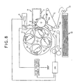
- FIG. 8 is a sectional view of a conventional color image forming apparatus.
- a photosensitive drum 1 serving as an image bearing member is driven in the direction indicated by the arrow by a driving means (not shown); it is charged uniformly by a primary charger 2.
- a laser beam L which is in conformity with an yellow image is applied to the photosensitive drum 1 from an exposure device 3, whereby a latent image is formed on the photosensitive drum 1.
- a developing device 4a containing yellow toner, of four developing devices 4a (yellow) , 4b (magenta), 4c (cyan) , and 4d (black) supported by a rotation supporting means 11 rotates to come to be opposed to the photosensitive drum 1, and the image is visualized by the yellow developing device 4a selected.
- An intermediate transfer belt 5 rotates in the direction of the arrow substantially at the same speed as the photosensitive drum 1.
- the toner image formed and borne on the photosensitive drum 1 undergoes primary transfer to the outer surface of the intermediate transfer belt 5 by a primary transfer bias applied to a primary transfer roller 8a.
- a transfer material is fed with a predetermined timing from a transfer material cassette 12 by means of pick-up rollers 13.
- a secondary transfer bias is applied to a secondary transfer roller 8b, and the toner image is transferred from the intermediate transfer belt 5 to the transfer material.
- the transfer material is conveyed by a conveyance belt 14 to a fixing device 6, where fusion and fixing are effected, whereby a color image is obtained.
- the toner remaining on the intermediate transfer belt 5 is removed by an intermediate transfer belt cleaner 15.
- the toner remaining on the photosensitive drum 1 is removed by a cleaning device 7 consisting of a well-known blade means.
- the photosensitive drum 1, the primary charger 2, and the cleaning device 7 are integrated into a process cartridge A, and the developing devices 4a, 4b, 4c, and 4d are also in the form of a developing cartridge which is easily detachable with respect to the apparatus main body, so that the maintenance operations can be easily conducted by the user.
- fluctuations in the density characteristics of the printed image are caused by the fluctuations in characteristics due to the use environment, the developing device, the number of sheets on which printing has been effected by the photosensitive drum, the variation in sensitivity generated at the time of the production of the photosensitive drum, the variation in frictional charging characteristics generated at the time of the manufacturing of the toner, etc.
- a plurality of toner images for detection are formed on the photosensitive drum 1 by varying the image forming condition stepwise, and the reflection light quantity thereof is measured by a density sensor 9 .
- an image forming condition which is likely to provide a desired density (reflection light quantity) is computed by a CPU 17 of the main body for image density control.
- the CPU 17 and the density sensor 9 correspond to image formation condition computing means constituting elements of the present invention used in the embodiment described below.
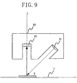
- Fig. 9 is a schematic view of the density sensor applied to the image forming apparatus shown in Fig. 8.
- the density sensor 9 is composed of a light emitting element 91 such as LED, a photoreceptor 92 such as a photo diode, and a holder 93. Infrared radiation from the light emitting element 91 is applied to a patch P on the photosensitive drum, and the reflected light therefrom is measured by the photoreceptor 92, whereby the density of the patch P is measured.
- a light emitting element 91 such as LED
- a photoreceptor 92 such as a photo diode
- the reflected light from the patch P contains a regular reflection component and an irregular reflection component.
- the light quantity of the regular reflection component undergoes great fluctuations depending on the condition of the photosensitive drum surface underneath the patch and fluctuation in the distance between the sensor and the patch.
- the detection accuracy deteriorates to a marked degree.
- the angle at which light is applied to the patch P is set to 45° and the reception angle of the reflected light from the patch P is set to 0° with respect to the normal I, thus measuring only the irregular reflection component.
- the photosensitive drum 1 is charged by the primary charger 2 such that its surface potential becomes -600V.
- the sensitivity of the photosensitive drum and the exposure amount of the laser are adjusted beforehand such that the potential of the laser exposure portion at normal temperature and normal humidity (23°C, 60% Rh) is approximately -200V.
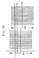
- the developing bias is obtained by superimposing a rectangular wave (with a frequency of 2000 Hz, 1800 Vpp) on a DC voltage, as shown in Fig. 10.
- a rectangular wave with a frequency of 2000 Hz, 1800 Vpp
- Vdc the DC voltage component
- Fig. 10 is a graph depicting the developing bias applied to the image forming apparatus shown in Fig. 8.
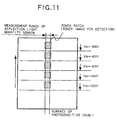
- a plurality of toner image patches of 30 mm square are printed at intervals, as shown in Fig. 11, on the portion of the drum corresponding to the density sensor 9 .
- Fig. 11 is a schematic diagram showing patches for density detection applied to the image forming apparatus shown in Fig. 8.
- the image patches are each developed by developing biases with different DC voltage components, and reflection light quantity measurement is performed on each of them by the density sensor 9.
- the number of image patches is five, the DC component Vdc of the developing bias being varied from -300V to -500V in steps of 50V.
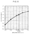
- Fig. 12 shows an example of the result of reflection density measurement.
- Fig. 12 is a graph showing the relationship between reflection density and developing bias in the image forming apparatus shown in Fig. 8.
- the target value of the reflection density of the toner (proper density value) is 1.4, and control is effected such that image formation is conducted under a developing condition estimated to be closest thereto (in this example, the DC voltage component of the developing bias).
- reflection density data as indicated by the five points in Fig. 12 was obtained.
- the developing condition providing the reflection density of 1.4 lies in the section where the DC component Vdc is between -400V and -450V. Assuming that DC component is approximately proportional to reflection density in this section, it is to be assumed, through interior division of the section between -400V and -450V, that the reflection density is 1.4 when the DC component is approximately -420V.
- the DC component Vdc of the developing bias as an image formation condition is controlled to be -420V.
- the above-described control is executed for each of the colors, Y, M, C, and K, whereby the image density control is completed.
- the image density control is executed prior to image formation (printing) each time printing is performed on a predetermined number of sheets , when the power source of the main body is ON , when replacing the process cartridge A or the development cartridges (developing devices) 4a, 4b, 4c, and 4d, and when a printing command is received when the apparatus has not been in use for a long period of time.
- the conventional color image forming apparatus has the following problems.
- the developing characteristics of the developing device and the photosensitive characteristics of the photosensitive drum fluctuate according to the condition of use of the apparatus, with the result that the image density varies.
- Fig. 13 is a graph showing the variation in image density when printing is successively executed in a conventional image forming apparatus.
- the vertical axis indicates density
- the horizontal axis indicates the number of sheets on which printing is performed.
- Broken line A indicates the proper image density for the apparatus
- broken line B indicates how the image density will change when image density control is not conducted each time printing has been conducted on a fixed number of sheets.
- Solid line C indicates how the image density changes when image density control is performed.
- image density control is effected each time printing has been performed on 100 sheets. Density control is effected at points in time indicated by numerals X1 and X2 in the drawing.
- the image density is prevented from being greatly deviated from the proper density for a long period of time.
- the user successively conducts the printing of the same image before and after density control. For example, if printing is successively performed on twenty sheets, for example, from the 90th to 110th sheet, there is the possibility of the image density of the first ten sheets being greatly different from that of the ten sheets after density control.
- Fig. 14 shows an example in which, conversely to the case of Fig. 13, image density is gradually reduced. As can be seen from this graph, a similar problem is involved also in this case.
- Fig. 14 is a graph showing the variation in image density when printing is successively executed in a conventional image forming apparatus.
- Another object of the present invention is to provide an image forming apparatus in which the difference in image density between an initial stage of use and a stage after long use is reduced.
- Still another object of the present invention is to provide an image forming apparatus in which a reduction in image forming speed when changing an image formation condition is mitigated.
- a further object of the present invention is to provide an image forming apparatus in which toner consumption for changing an image formation condition is restrained.
- a further object of the present invention is to provide an image forming apparatus in which it is possible to change an image formation condition gradually and stepwise.
- an image forming apparatus comprising:
- a gradual increase or decrease in image formation condition is effected, from a first image formation condition selected immediately before the execution of image density control toward a second image formation condition calculated through image density control, whereby an abrupt variation in density is prevented.
- the main construction of the color image forming apparatus used in this embodiment is the same as that of the conventional color image forming apparatus described with reference to Fig. 8, so that a detailed description thereof will be omitted, and the components shown in Fig. 8 will be referred to as appropriate.
- the DC component of a developing bias which constitutes a developing condition, is used as the image formation condition to be changed so as to control image density.
- Fig. 1 is a flowchart showing an image forming operation applicable to the first embodiment of the image forming apparatus of the present invention.
- image density control is executed in any one of the following conditions.
- toner images for detection are formed on the photosensitive drum 1.
- toner patches are formed on the photosensitive drum 1.
- the DC component Vdc of the developing bias is varying the DC component Vdc of the developing bias from -300V to -500V in steps of 50V.
- the densities of the toner patches formed in STEP 1 are measured by the density sensor 9.
- the CPU 17 calculates an optimum DC voltage (optimum developing bias) á0.
- the value of the optimum developing bias á0 is a value at which the toner patch density is 1.4, which is the proper density for this image forming apparatus.
- the optimum developing bias value á0 obtained is stored in a memory (not shown) in the main body.
- the main body memory may be volatile or nonvolatile. In this embodiment, a volatile memory is used.
- a print developing bias á1 is prepared as the developing bias value to be used at the time of printing, separately from the optimum developing bias value á0, and is stored in the main body memory.
- the procedure advances to STEP 7, and the optimum developing bias á0 obtained through image density control is input to the print developing bias value á1.
- the image density control executed is that which is conducted when printing has been performed on a predetermined number of sheets (100 sheets in this embodiment).
- the print developing bias value á1 stored in the main body memory is the developing bias value used immediately before the image density control.
- the above image density control is performed on each of the colors Y, M, C, and K, and the image density control is completed.
- the optimum developing bias value á0 and the print developing bias value á1 are provided independently for each of the colors (Y, M, C, and K), and stored in the main body memory for the respective colors.
- Fig. 2 is a flowchart illustrating an image forming operation applicable to the first embodiment of the image forming apparatus of the present invention.
- the developing bias calculation at the time of printing is conducted for each print sheet. That is, each time printing is performed, the operation of the flowchart is started and executed.
- the developing bias value á1 used in the previous printing is compared with the developing bias value á0 calculated through image density control.
- á0 is larger than á1
- the procedure advances to STEP 22.
- a developing bias adjustment value â is added to the developing bias value á1 used in the previous printing (the value corresponding to the image formation condition before changing) to update the print developing bias value á1.
- the developing bias adjustment value â is an adjustment value for adjusting and varying the developing bias for each print sheet; it is preferably set to an optimum value according to the characteristics of the apparatus.
- this adjustment value â when this adjustment value â is set to a small value, the fluctuation in density for each print sheet is diminished. When, conversely, it is set to a large value, the fluctuation in density increases.
- the developing bias adjustment value â is set to 0.5V in this embodiment.
- the updated bias value á1 is compared with the optimum developing bias á0 calculated through image density control (the value corresponding to the image formation condition after the change).
- the print developing bias value á1 is calculated independently for each of the colors (Y, M, C, and K).
- FIG. 3 is a graph showing how developing bias and density change with respect to the number of print sheets in the first embodiment of the image forming apparatus of the present invention.
- Fig. 3A shows how the developing bias for printing changes
- Fig. 3B shows how the density changes.
- the solid line E indicates how the developing bias changes in this embodiment
- the dotted line F indicates how the developing bias changes in the conventional control.
- the image density control is executed for 100 print sheets (as indicated by X1 and X2 in the drawings).
- the solid line D indicates how the image density changes when this embodiment is adopted
- the dotted line C indicates how the density changes in the conventional control.
- the print developing bias is updated immediately after the execution of image density control, so that the change in density before and after the control is rather great, whereas in the bias control of this embodiment, no abrupt change in density occurs.
- the image formation condition is gradually increased or decreased from the first image formation condition which has been selected toward the second image formation condition calculated through image density control, whereby it is possible to prevent an abrupt change in density.
- an image forming apparatus in which a gradual increase or decrease in image formation condition is effected from a first image formation condition selected immediately before the execution of image density control toward a second image formation condition calculated through image density control at a rate of change corresponding to the difference between the first image formation condition and the second image formation condition, whereby an abrupt change in density is prevented, and the image density is prevented from being greatly deviated from a proper density for a long period of time.
- the DC component of the developing bias is used as the image formation condition to be changed for image density control.
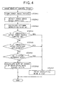
- Fig. 4 is a flowchart illustrating an image forming operation applicable to the second embodiment of the image forming apparatus of the present invention.
- Toner images for detection are formed on the photosensitive drum 1, and the densities of the toner patches are measured by the density sensor 9.
- the optimum developing DC voltage (optimum developing bias) á0 which is a value in correspondence with the second image formation condition is calculated.
- the above method is similar to that of the first embodiment, so that a detailed description thereof will be omitted.
- the image density control executed is that which is to be conducted when printing has been performed on a predetermined number of sheets (100 sheets in this embodiment).
- variation is effected while gradually increasing or decreasing the developing bias from immediately after the image density control, calculating the rate of change â of the developing bias used at this time.
- Rate of change â of the developing bias (optimum developing bias á0 - developing bias á1 immediately before density control) ⁇ K (where K is a predetermined constant)
- the rate of change â of the developing bias is determined according to the difference between the optimum developing bias á0 (the control value corresponding to the second image formation condition) and the developing bias á1 immediately before density control (the control value corresponding to the first image formation condition), so that regardless of the magnitude of the difference, the developing bias used becomes equal to the optimum developing bias when printing is performed on a fixed number of sheets (represented by K in the above equation). That is, when the developing bias for density control achieves the level of K, the developing bias is changed to the optimum developing bias.
- the predetermined constant K be set to an optimum value according to the characteristics of the apparatus.
- the value of the predetermined constant K is set to 25 in this embodiment.
- the above image density control is conducted for each of the colors, Y, M, C, and K to complete the image density control.
- the optimum developing bias value á0, the print developing bias value á1, and the rate of change â of the developing bias are independently provided for each of the colors (Y, M, C, and K) and are separately stored in the main body memory.
- the control of the developing bias at the time of printing is the same as that in the first embodiment (Fig. 2).
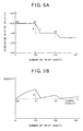
- Figs. 5A and 5B are graphs showing how the developing bias and the density change with respect to the number of print sheets in the second embodiment of the image forming apparatus of the present invention.
- Fig. 5A illustrates how the developing bias for printing changes
- Fig. 5B illustrates how the density changes.
- the solid line E indicates the change of the developing bias in this embodiment
- the dotted line F indicates the change of the developing bias in the conventional control.
- the image density control is executed each time printing has been performed on 100 sheets (as indicated by X0, X1, and X2 in the drawings).
- the solid line D indicates the change of the image density when this embodiment is adopted
- the dotted line C indicates the density change in the case of a conventional control.
- the print developing bias is updated immediately after the execution of image density control, so that the density change is very remarkable before and after the control, whereas, when the bias control of this embodiment is adopted, no abrupt change in density is caused.
- the rate of change of the developing bias is varied according to the difference between the optimum developing bias and the developing bias immediately before density control, so that, even when the difference is large, it is possible to prevent the image density from being greatly deviated from the proper density for a long period of time (At point X1 in the drawing, the value of the solid line D is not greatly deviated from the proper density A for a long period of time).
- the image formation condition is gradually increased or decreased from the first image formation condition selected immediately before the execution of image density control toward the second image formation condition calculated through image density control at a rate of change in correspondence with the difference between the first image formation condition and the second image formation condition , whereby an abrupt change in density is prevented, and it is possible to prevent the image density from being greatly deviated from the proper density for a long period of time.
- the second image formation condition is used from immediately after the execution of the image density control. Otherwise, the image formation condition is gradually increased or decreased from the first image formation condition selected immediately before the execution of image density control toward the second image formation condition calculated through image density control, whereby an abrupt change in density is prevented, and it is possible to prevent the image density from being greatly deviated from the proper density for a long period of time.
- the DC component of the developing bias is used as the image formation condition to be varied so as to control the image density.
- Fig. 6 is a flowchart illustrating an image forming operation applicable to the third embodiment of the image forming apparatus of the present invention.
- Toner images for detection are formed on the photosensitive drum 1, and the densities of the toner patches are measured by the density sensor 9. Further, from the results of the measurement of the toner patch densities, an optimum developing DC voltage (optimum developing bias) á0 is calculated.
- the above-described method is the same as that of the first embodiment, so a detailed description thereof will be omitted.
- the image density control is executed when printing has been performed on a predetermined number of sheets (100 sheets in this embodiment).
- the difference in density before and after the control is not so great even if the optimum developing bias á0 is used from immediately after the density control.
- control is performed such that the proper density can be achieved immediately (The procedure advances to STEP 69).
- the predetermined constant ⁇ is set to an optimum value according to the characteristics of the apparatus . Specifically, it is desirable for the value of ⁇ to be set such that the density fluctuation when the developing bias is varied by ⁇ is equal to the maximum value of the density fluctuation permissible to the user. Taking the above into consideration, the predetermined difference value ⁇ is set to 20V in this embodiment.
- the rate of change â of the developing bias used when varying the developing bias while gradually increasing or decreasing it is calculated.
- the method of calculating the rate of change â of the developing bias is the same as that in the second embodiment.
- the value used when varying the developing bias while gradually increasing or decreasing may be a predetermined value as in the first embodiment described above.
- the above image density control is performed for each of the colors Y, M, C, and K to complete the image density control.
- the developing bias control at the time of printing is the same as that in the first embodiment described above (Fig. 2).
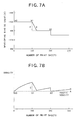
- Figs. 7A and 7B are graphs showing how the developing bias and the density change with respect to the number of print sheets in the third embodiment of the image forming apparatus of the present invention.
- Fig. 7A shows the way the developing bias for printing changes
- Fig. 7B shows the way the density changes.
- the solid line E indicates the change in the developing bias in this embodiment
- the dotted line F indicates the change in the developing bias in the conventional control.
- Image density control is executed each time printing has been performed on 100 sheets (as indicated by points X0, X1, and X2 in the drawing).
- the solid line D indicates the change in the image density when this embodiment is applied
- the dotted line C indicates the change in the density in the conventional control.
- the developing bias is gradually varied from after the execution of the density control, so that no abrupt change in density is caused (at point X1 in the drawing).
- the second image formation condition when the difference between the first image formation condition selected immediately before the execution of image density control and the second image formation condition calculated through image density control is smaller than a predetermined value, the second image formation condition is used from immediately after the execution of the image density control. Otherwise, the image formation condition is gradually increased or decreased from the first image formation condition selected immediately before the execution of the image density control toward the second image formation condition calculated through image density control, whereby an abrupt change in density is prevented, and it is possible to prevent the image density from being greatly deviated from the proper density for a long period of time.
- an optimum image formation condition is calculated for each print from the condition of use of the photosensitive drum or the developing device, the use environment of the apparatus detected by an environment sensor, etc., and is varied.
- the image formation condition is gradually increased or decreased from the first image formation condition selected immediately before the execution of image density control toward the second image formation condition calculated through image density control, whereby it is possible to prevent an abrupt change in density.
- the second image formation condition is used from immediately after the execution of the image density control, whereby it is possible to quickly achieve the proper density.
- the invention provides an image forming apparatus and a method of manufacturing thereof which is capable of continuously forming images with proper density without reducing the image forming speed and, retrains toner consumption.
- a CPU for calculating an image forming condition by a density sensor is provided.
- the image forming operation is conducted in basis of a calculated new image forming condition and a current image forming condition used prior to the calculation of a new image forming condition in the image forming operation so as to determine an available image forming condition.
Landscapes
- Engineering & Computer Science (AREA)
- Microelectronics & Electronic Packaging (AREA)
- Physics & Mathematics (AREA)
- General Physics & Mathematics (AREA)
- Control Or Security For Electrophotography (AREA)
- Developing For Electrophotography (AREA)
- Dry Development In Electrophotography (AREA)
Abstract
Description
Claims (18)
- An image forming apparatus comprising:an image forming means for forming an image on a recording material;a detecting means for detecting an image density; anda changing means for changing a former image formation condition for the image forming means to a next image formation condition for the image forming means on the basis of a detection result of the detecting means, wherein the changing means is capable of changing the former image formation condition so as to bring it close to the next image formation condition through a stepwise change of image formation condition.
- An image forming apparatus according to Claim 1, wherein when a first value corresponding to the next image formation condition is smaller than a second value corresponding to the former image formation condition, subtraction of a predetermined value is performed on the second value to thereby determine the stepwise change of image formation condition, and wherein when the first value corresponding to the next image formation condition is larger than the second value corresponding to the former image formation condition, a predetermined value is added to the second value to thereby determine the stepwise change of image formation condition.
- An image forming apparatus according to Claim 1, wherein when a first value corresponding to the next image formation condition is smaller than a second value corresponding to the former image formation condition, subtraction is performed in accordance with a rate of change of the second value and the first value to thereby determine the stepwise change of image formation condition, and wherein when the first value corresponding to the next image formation condition is larger than the second value corresponding to the former image formation condition, addition is performed in accordance with the rate of change to thereby determine the stepwise change of image formation condition.
- An image forming apparatus according to Claim 1, wherein the stepwise change of image formation condition is effected each time image forming operation is performed.by the image forming means.
- An image forming apparatus according to Claim 2 or 3, wherein when the subtraction results in a value not larger than the first value, or when the addition results in a value not smaller than the first value, an image formation condition corresponding to the first value is used.
- An image forming apparatus according to Claim 1, wherein when a difference between the former image formation condition and the next image formation condition is within a predetermined range, the former image formation condition is set without performing the stepwise change of image formation condition.
- An image forming apparatus according to Claim 1, wherein when, after a power source of the apparatus is turned on, the image density is detected by the detecting means before the image formation by the image forming means is started, the first image formation condition of the image forming means is set without performing the stepwise change of image formation condition.
- An image forming apparatus according to Claim 1, wherein when the image density is detected by the image detecting means after a predetermined period of time when the apparatus has not been used, the first image formation condition of the image forming means is set without performing the stepwise change of image formation condition.
- An image forming apparatus according to Claim 1, wherein the apparatus has a process cartridge detachable with respect to a main body of the apparatus, wherein the process cartridge is equipped with an image bearing member and a charging means for charging the image bearing member, and wherein when the image density is detected by the detecting means after the process cartridge is replaced, the first image formation condition of the image forming means is set without performing the stepwise change of image formation condition.
- An image forming apparatus according to Claim 1, wherein the image forming means includes an image bearing member, a toner image forming means for forming a toner image on the image bearing member, and a transfer means for transferring the toner image to the recording material.
- An image forming apparatus according to Claim 10, wherein the image formation condition is a toner image formation condition for the toner image forming means.
- An image forming apparatus according to Claim 11, wherein the toner image forming means is equipped with an electrostatic image forming means for forming an electrostatic image on the image bearing member and a developing means for developing the electrostatic image with toner, and wherein the image formation condition is at least one of an electrostatic image formation condition for the electrostatic image forming means and a development condition for the developing means.
- An image forming apparatus according to Claim 12, wherein the development condition is a DC voltage applied to the developing means.
- An image forming apparatus according to Claim 12, wherein the image bearing member is a photosensitive member, wherein the electrostatic image forming means is equipped with a charging means for charging the photosensitive member and an exposure means for subjecting the photosensitive member charged by the charging means to exposure, and wherein the electrostatic image formation condition is at least one of a charging condition for the charging means and an exposure condition for the exposure means.
- An image forming apparatus according to Claim 1, wherein the detecting means detects the image density each time the image forming means has formed a predetermined number of images.
- An image forming apparatus according to Claim 1, wherein the detecting means is a detection sensor for detecting the density of a toner image.
- An image forming apparatus according to Claim 16, wherein the detection sensor is equipped with a light emitting portion for applying light to the toner image and a light receiving portion for receiving light applied to the toner image.
- An image forming apparatus according to Claim 1, wherein the image forming means is capable of forming a color image on the recording material.
Applications Claiming Priority (2)
| Application Number | Priority Date | Filing Date | Title |
|---|---|---|---|
| JP2000261657A JP4719343B2 (en) | 2000-08-30 | 2000-08-30 | Image forming apparatus |
| JP2000261657 | 2000-08-30 |
Publications (3)
| Publication Number | Publication Date |
|---|---|
| EP1184731A2 true EP1184731A2 (en) | 2002-03-06 |
| EP1184731A3 EP1184731A3 (en) | 2004-12-22 |
| EP1184731B1 EP1184731B1 (en) | 2009-08-26 |
Family
ID=18749464
Family Applications (1)
| Application Number | Title | Priority Date | Filing Date |
|---|---|---|---|
| EP01120572A Expired - Lifetime EP1184731B1 (en) | 2000-08-30 | 2001-08-29 | Image forming apparatus with changeable image formation condition |
Country Status (4)
| Country | Link |
|---|---|
| US (1) | US6505012B2 (en) |
| EP (1) | EP1184731B1 (en) |
| JP (1) | JP4719343B2 (en) |
| DE (1) | DE60139664D1 (en) |
Cited By (4)
| Publication number | Priority date | Publication date | Assignee | Title |
|---|---|---|---|---|
| US7068957B2 (en) | 2002-07-19 | 2006-06-27 | Seiko Epson Corporation | Image forming apparatus and image forming method involving application of a developing bias to a toner carrier |
| EP1400863A3 (en) * | 2002-08-22 | 2006-11-29 | Seiko Epson Corporation | Image forming apparatus and method with controlled image forming condition |
| CN101017353B (en) * | 2002-08-22 | 2010-07-28 | 精工爱普生株式会社 | Image forming apparatus and method |
| EP1462861A3 (en) * | 2003-01-31 | 2011-10-05 | Canon Kabushiki Kaisha | Image forming apparatus and control method for the same |
Families Citing this family (2)
| Publication number | Priority date | Publication date | Assignee | Title |
|---|---|---|---|---|
| JP5253825B2 (en) * | 2008-01-16 | 2013-07-31 | 京セラドキュメントソリューションズ株式会社 | Image forming apparatus |
| JP5301576B2 (en) * | 2011-02-03 | 2013-09-25 | シャープ株式会社 | Image forming apparatus and image forming method |
Family Cites Families (9)
| Publication number | Priority date | Publication date | Assignee | Title |
|---|---|---|---|---|
| JPS5529859A (en) * | 1978-08-24 | 1980-03-03 | Canon Inc | Image former |
| JP3098138B2 (en) * | 1993-07-06 | 2000-10-16 | キヤノン株式会社 | Image forming device |
| JPH08110700A (en) * | 1994-10-11 | 1996-04-30 | Ricoh Co Ltd | Image forming device |
| JP3360449B2 (en) * | 1994-12-15 | 2002-12-24 | 富士ゼロックス株式会社 | Image density control device |
| JPH08202137A (en) * | 1995-01-24 | 1996-08-09 | Ricoh Co Ltd | Toner density control device in image forming apparatus |
| JP3282964B2 (en) * | 1996-03-21 | 2002-05-20 | シャープ株式会社 | Image stabilizing method for image forming apparatus |
| JPH11295942A (en) * | 1998-04-09 | 1999-10-29 | Canon Inc | Image forming device |
| JP3482131B2 (en) * | 1998-08-03 | 2003-12-22 | シャープ株式会社 | Image forming device |
| US6118953A (en) * | 1998-09-18 | 2000-09-12 | Eastman Kodak Company | Electrostatographic apparatus and method with programmable toner concentration decline with the developer life |
-
2000
- 2000-08-30 JP JP2000261657A patent/JP4719343B2/en not_active Expired - Lifetime
-
2001
- 2001-08-29 EP EP01120572A patent/EP1184731B1/en not_active Expired - Lifetime
- 2001-08-29 DE DE60139664T patent/DE60139664D1/en not_active Expired - Lifetime
- 2001-08-29 US US09/940,493 patent/US6505012B2/en not_active Expired - Lifetime
Cited By (7)
| Publication number | Priority date | Publication date | Assignee | Title |
|---|---|---|---|---|
| US7068957B2 (en) | 2002-07-19 | 2006-06-27 | Seiko Epson Corporation | Image forming apparatus and image forming method involving application of a developing bias to a toner carrier |
| US7251423B2 (en) | 2002-07-19 | 2007-07-31 | Seiko Epson Corporation | Image forming apparatus and image forming method |
| EP1400863A3 (en) * | 2002-08-22 | 2006-11-29 | Seiko Epson Corporation | Image forming apparatus and method with controlled image forming condition |
| CN101017353B (en) * | 2002-08-22 | 2010-07-28 | 精工爱普生株式会社 | Image forming apparatus and method |
| EP1462861A3 (en) * | 2003-01-31 | 2011-10-05 | Canon Kabushiki Kaisha | Image forming apparatus and control method for the same |
| US8155550B2 (en) | 2003-01-31 | 2012-04-10 | Canon Kabushiki Kaisha | Printer engine having a judgment unit and a control unit that transmits to a controller |
| EP2541331A1 (en) * | 2003-01-31 | 2013-01-02 | Canon Kabushiki Kaisha | Image forming apparatus with a control method for the same |
Also Published As
| Publication number | Publication date |
|---|---|
| US20020028084A1 (en) | 2002-03-07 |
| EP1184731A3 (en) | 2004-12-22 |
| DE60139664D1 (en) | 2009-10-08 |
| JP4719343B2 (en) | 2011-07-06 |
| JP2002072584A (en) | 2002-03-12 |
| US6505012B2 (en) | 2003-01-07 |
| EP1184731B1 (en) | 2009-08-26 |
Similar Documents
| Publication | Publication Date | Title |
|---|---|---|
| US8265500B2 (en) | Image forming apparatus | |
| JP5418914B2 (en) | Image forming apparatus | |
| JP4866583B2 (en) | Image forming apparatus | |
| US10197939B2 (en) | Image forming apparatus with a control that compensates for changing humidity | |
| EP1659453B1 (en) | Exposure control method according to photoconductor usage in image forming apparatus | |
| JP4858583B2 (en) | Color image forming apparatus | |
| EP1251410B1 (en) | Image forming apparatus and control means for the amount of developer on the image carrier | |
| US6505012B2 (en) | Image forming apparatus | |
| JP2014119665A (en) | Image forming apparatus | |
| US7242876B2 (en) | Image forming apparatus with developer supply amount target value correcting feature using detected data relating to apparatus ambient environment and information relating to a sealed developer supply container environment | |
| US10496008B2 (en) | Toner supplying means and image forming apparatus comprising the same | |
| JP5262671B2 (en) | Image forming apparatus and image forming method | |
| US20020127027A1 (en) | Image forming apparatus | |
| JPH10232523A (en) | Image forming device | |
| JP4887949B2 (en) | Image forming apparatus and toner density control method | |
| JP5168851B2 (en) | Image forming apparatus | |
| JP2009069506A (en) | Image forming apparatus | |
| US20060257159A1 (en) | White vector feedback adjustment | |
| JP6701800B2 (en) | Image forming device | |
| US7324768B2 (en) | Method and device for determining one or more operating points in an image forming device | |
| US20240353783A1 (en) | Image forming apparatus | |
| JP2001255711A (en) | Image forming device | |
| JP4951993B2 (en) | Image forming apparatus | |
| JP6662734B2 (en) | Image forming apparatus, control program, and control method | |
| JP2023112296A (en) | Image forming device adjustment method and image forming device |
Legal Events
| Date | Code | Title | Description |
|---|---|---|---|
| PUAI | Public reference made under article 153(3) epc to a published international application that has entered the european phase |
Free format text: ORIGINAL CODE: 0009012 |
|
| AK | Designated contracting states |
Kind code of ref document: A2 Designated state(s): AT BE CH CY DE DK ES FI FR GB GR IE IT LI LU MC NL PT SE TR |
|
| AX | Request for extension of the european patent |
Free format text: AL;LT;LV;MK;RO;SI |
|
| PUAL | Search report despatched |
Free format text: ORIGINAL CODE: 0009013 |
|
| AK | Designated contracting states |
Kind code of ref document: A3 Designated state(s): AT BE CH CY DE DK ES FI FR GB GR IE IT LI LU MC NL PT SE TR |
|
| AX | Request for extension of the european patent |
Extension state: AL LT LV MK RO SI |
|
| 17P | Request for examination filed |
Effective date: 20050614 |
|
| AKX | Designation fees paid |
Designated state(s): DE FR GB IT |
|
| 17Q | First examination report despatched |
Effective date: 20061207 |
|
| RTI1 | Title (correction) |
Free format text: IMAGE FORMING APPARATUS WITH CHANGEABLE IMAGE FORMATION CONDITION |
|
| GRAP | Despatch of communication of intention to grant a patent |
Free format text: ORIGINAL CODE: EPIDOSNIGR1 |
|
| GRAS | Grant fee paid |
Free format text: ORIGINAL CODE: EPIDOSNIGR3 |
|
| GRAA | (expected) grant |
Free format text: ORIGINAL CODE: 0009210 |
|
| RAP1 | Party data changed (applicant data changed or rights of an application transferred) |
Owner name: CANON KABUSHIKI KAISHA |
|
| AK | Designated contracting states |
Kind code of ref document: B1 Designated state(s): DE FR GB IT |
|
| REG | Reference to a national code |
Ref country code: GB Ref legal event code: FG4D |
|
| REF | Corresponds to: |
Ref document number: 60139664 Country of ref document: DE Date of ref document: 20091008 Kind code of ref document: P |
|
| PGFP | Annual fee paid to national office [announced via postgrant information from national office to epo] |
Ref country code: IT Payment date: 20090807 Year of fee payment: 9 |
|
| PLBE | No opposition filed within time limit |
Free format text: ORIGINAL CODE: 0009261 |
|
| STAA | Information on the status of an ep patent application or granted ep patent |
Free format text: STATUS: NO OPPOSITION FILED WITHIN TIME LIMIT |
|
| 26N | No opposition filed |
Effective date: 20100527 |
|
| REG | Reference to a national code |
Ref country code: FR Ref legal event code: ST Effective date: 20110502 |
|
| PG25 | Lapsed in a contracting state [announced via postgrant information from national office to epo] |
Ref country code: IT Free format text: LAPSE BECAUSE OF NON-PAYMENT OF DUE FEES Effective date: 20100829 |
|
| PG25 | Lapsed in a contracting state [announced via postgrant information from national office to epo] |
Ref country code: FR Free format text: LAPSE BECAUSE OF NON-PAYMENT OF DUE FEES Effective date: 20100831 |
|
| PGFP | Annual fee paid to national office [announced via postgrant information from national office to epo] |
Ref country code: FR Payment date: 20090908 Year of fee payment: 9 |
|
| PGFP | Annual fee paid to national office [announced via postgrant information from national office to epo] |
Ref country code: GB Payment date: 20200825 Year of fee payment: 20 |
|
| PGFP | Annual fee paid to national office [announced via postgrant information from national office to epo] |
Ref country code: DE Payment date: 20201029 Year of fee payment: 20 |
|
| REG | Reference to a national code |
Ref country code: DE Ref legal event code: R071 Ref document number: 60139664 Country of ref document: DE |
|
| REG | Reference to a national code |
Ref country code: GB Ref legal event code: PE20 Expiry date: 20210828 |
|
| PG25 | Lapsed in a contracting state [announced via postgrant information from national office to epo] |
Ref country code: GB Free format text: LAPSE BECAUSE OF EXPIRATION OF PROTECTION Effective date: 20210828 |