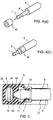
TECHNICAL FIELD
The present invention relates to a subminiature optical
connector comprising a subminiature single head optical plug the
sleeve of which is approximately 2.5 mm in its outside diameter and a
connecting terminal into which the optical plug is to be inserted, and
to a portable type electronic apparatus having the connecting terminal
of the optical connector mounted thereto. More particularly, the
present invention relates to a subminiature optical connector having a
subminiature single head optical plug which can be used in
transmitting an optical signal as well as in transmitting an electrical
signal, and to a portable type electronic apparatus having a connecting
terminal of the optical connector mounted thereto.
BACKGROUND ART
Miniature audio visual apparatus such as a DVD (Digital
Versatile Disk) player/recorder, MD (Mini-Disk) player/recorder, CD
(Compact Disk) player/recorder and the like, portable audio apparatus
such as an MD portable player/recorder, CD portable player/recorder,
memory type audio apparatus (audio apparatus using a memory stick)
and the like, or mobile communication apparatus such as a mobile
phone, pocket or portable telephone and the like have been
miniaturized more and more in their external forms or shapes and
sizes, and accordingly, an input terminal and/or output terminal built
in or mounted to these electronic apparatus have been also
miniaturized. Particularly, in recent years, with the advance of optical
technology, there have been provided many kinds of audio visual
apparatus, portable audio apparatus, mobile communication apparatus
and the like, each being provided with an optical input terminal and/or
output terminal for an optical or light signal. These electronic
apparatus provided with an optical input terminal and/or output
terminal have been also miniaturized.
The above-mentioned various types of miniature electronic
apparatus have signal input terminals and/or signal output terminals
for an audio signal, video signal, etc., mounted thereto, and recently,
there are many miniature electronic apparatus that have not only
signal input terminals and/or signal output terminals for an electrical
signal mounted thereto but also signal input terminals and/or signal
output terminals for an optical signal mounted thereto. Generally, a
connecting terminal (a receptacle or jack) of a miniature connector is
used as those input/output terminals, and a plug of the miniature
connector is inserted into the connecting terminal (hereinafter,
referred to as receptacle) so that the receptacle and the plug can be
electrically or optically connected with each other, the plug having a
cable (for example, coaxial cable) that transmits an electrical signal or
a cable (for example, optical fiber) that transmits an optical or light
signal connected thereto.
In respect of a plug of a miniature electrical connector, to
which a cable that transmits an electrical signal is connected, a "two-electrode
or three-electrode subminiature single head plug" the sleeve
of which is 2.5 mm in its outside diameter has been prescribed by JIS
(Japanese Industrial Standard) C6560, and is put to practical use.
However, in respect of a plug of a subminiature optical connector, to
which a cable that transmits an optical signal is connected, there is
prescribed by EIAJ (Electronic Industries Association of Japan) (EIAJ
RC-5720A) only a miniature optical plug the sleeve of which is 3.5
mm in its outside diameter at the minimum, and a subminiature single
head optical plug having its sleeve of the same outside diameter as
that (2.5 mm) of the sleeve of the two-electrode or three-electrode
subminiature single head plug for only electrical signal use prescribed
by JIS C6560 has not been prescribed yet by EIAJ or other standards.
Of course, a subminiature optical receptacle corresponding to the
subminiature single head optical plug has not been prescribed by EIAJ
or other standards, either.
Now, the two-electrode subminiature single head plug of the
"two-electrode or three-electrode subminiature single head plug"
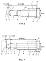
prescribed by JIS C6560 will be described with reference to Fig. 6.
As shown in Fig. 6, the two-electrode subminiature single head
plug 10 prescribed by JIS C6560 comprises a sleeve 4 the outside
diameter of which has been determined to 2.5 mm as discussed above.
The root of the sleeve 4 is fixed to a stem 5 having its outside
diameter larger than that of the sleeve 4, and a hollow tip 1 is mounted
to the front end of the sleeve 4 through an insulation collar 2. This
subminiature single head plug 10 is configured such that the length
extending from the rear end of the sleeve 4 which is equivalent in
position to the front end surface 51 of the stem 5 to a position 11 of
the tip 1 where its outside diameter is the maximum (the maximum
diameter position of the tip 1) is determined to (10.3 ± 0.3) mm as
well as the length from the maximum diameter position 11 of the tip 1
to the front end 12 of the tip 1 is determined to (0.7 ± 0.3) mm.
Accordingly, the overall length of the two-electrode subminiature
single head plug 10 is
(10.3 + 0.3) + (0.7 + 0.3) = 11.6 mm
at the maximum, and is
(10.3 - 0.3) + (0.7 - 0.3) = 10.4 mm
at the minimum.
Further, a three-electrode subminiature single head plug,
though it is not shown, is also configured such that the length from the
rear end of a sleeve to the maximum diameter position of a tip as well
as the length from the maximum diameter position of the tip to the
front end of the tip are determined to the same lengths as those of the
two-electrode subminiature single head plug 10 explained above,
except that the sleeve of the three-electrode subminiature single head
plug has three electrodes provided thereto. Accordingly, the overall
length of the three-electrode subminiature single head plug is also
determined to the same as that of the two-electrode subminiature
single head plug 10.
In case of the subminiature single head connector for only
electrical signal use, a receptacle corresponding to the aforesaid two-electrode
or three-electrode subminiature single head plug 10 having
the sleeve of 2.5 mm in its outside diameter is also prescribed by JIS,
and the two-electrode or three-electrode subminiature single head plug
10 is used in the manner that it is inserted into such receptacle.
Since the two-electrode or three-electrode subminiature single
head plug 10 has been prescribed as mentioned above, the overall
length of this plug 10 is, on taking the above allowance into
consideration, 11.6 mm in case of a product of the longest overall
length as described above. When such two-electrode or three-electrode
subminiature single head plug 10 is inserted into a
corresponding receptacle 9, the two-electrode or three-electrode
subminiature single head plug 10 is checked in its further insertion by
the front end surface 51 of the stem 5 abutting against the end surface
61 of the approach to an inserting hole of the corresponding receptacle
9 in which the plug 10 is to be fitted. As a result, the front end 12 of
the tip 1 of the plug 10 will be located in a position between 10.4 mm
that is the shortest length of the plug 10 measured from the end
surface 61 of the approach and 11.6 mm that is the longest length of
the plug 10 measured from the end surface 61 of the approach.
As discussed above, various types of miniature electronic
apparatus show a tendency to be miniaturized more and more. Each of
miniature electronic apparatus having a receptacle for receiving an
optical signal and/or a receptacle for outputting an optical signal
mounted thereto is provided with a receptacle corresponding to an
optical plug the sleeve of which is 3.5 mm in its outside diameter,
because in the existing circumstances, only an optical plug the sleeve
of which is 3.5 mm in its outside diameter at the minimum and a
receptacle into which this optical plug is to be inserted have been
prescribed. In order to further miniaturize such miniature electronic
apparatus, the external form or shape and size of the optical receptacle
to be mounted thereto must be reduced. For this reason, there is
increasing more and more a necessity of developing a subminiature
single head optical plug having its sleeve the outside diameter of
which is 2.5 mm as well as an optical receptacle into which such
optical plug is to be inserted.
Now, in case that a subminiature single head optical plug is
manufactured with its external shape and size substantially equal to
those of the aforesaid two-electrode or three-electrode subminiature
single head plug for only electrical signal use prescribed by JIS C6560,
as shown in Fig. 7, the front end surface of the core 71 of an optical
fiber 7 is located in the hollow tip 1 of the subminiature single head
optical plug 10 at the immediate inner side of the front end 12 of the
hollow tip 1. When such subminiature single head optical plug 10 is
inserted into the corresponding optical receptacle 9, the front end of
the core 71 of the optical fiber 7 is opposite to and approaches an
optical element 8 accommodated in the optical receptacle 9 so that
light can be incident upon the optical element 8 from the optical fiber
7 or upon the optical fiber 7 from the optical element 8, and an optical
signal can be transmitted therebetween. Further, in case of the optical
plug, it is unnecessary to provide an insulation collar 2. Accordingly,
in Fig. 7, the tip 1 is directly mounted to the sleeve 4.
In such case, if the overall length of the subminiature
single head optical plug 10 is too long as compared with the depth
of the receptacle 9, it is feared that the front end 12 of the tip 1 of
the subminiature single head optical plug 10 will collide against the
optical element 8 or a lens located at the front of the optical element
8 so that the optical element 8 or the lens will be damaged.
Therefore, in order to prevent the optical element 8 or the lens
located at the front thereof from being damaged even if a
subminiature plug the overall length of which is 11.6 mm is inserted
into the optical element 8, 11.6 mm being equal to the maximum
length of the subminiature single head plug prescribed by JIS C6560,
the optical element 8 is located at a position that has entered toward
the inside of the receptacle 9 by at least 11.6 mm from the end
surface 61 of the approach to the inserting hole of the receptacle 9.
As a result, in case that the subminiature single head optical plug 10
of 11.6 mm in its overall length equal to the maximum length is
inserted into the receptacle 9, a distance between the front end of
the tip 1 and the optical element 8 opposed thereto approximates to
zero (0 mm). In contrast thereto, in case that the subminiature
single head optical plug 10 of 10.4 mm in its overall length equal to
the minimum length is inserted into the receptacle 9, a distance
between the front end of the tip 1 and the optical element 8 opposed
thereto approximates to 1.2 mm. Accordingly, the difference in the
distance between the front end of the tip 1 and the optical element 8
ranges from substantially zero to about 1.2 mm due to the
unevenness in manufacture relating to the overall length of each of
products of the subminiature single head optical plugs.
Consequently, the difference in the space between the front end
surface of the core 71 of the optical fiber 7 located at the immediate
inner side of the front end of the tip 1 and the optical element 8 also
ranges from substantially zero to about 1.2 mm.
As described above, the space between the front end surface
of the core 71 of the optical fiber 7 and the optical element 8
opposed to the front end surface extends over a wide range such as
from substantially 0 mm to about 1.2 mm. As a result, there occurs
a considerable difference in quantity of light that is incident upon
the optical element 8 from the optical fiber 7 or incident upon the
optical fiber 7 from the optical element 8, which results in an
important problem that transmission of an optical signal is adversely
affected. Therefore, even though a subminiature single head optical
plug is designed and manufactured as JIS C6560 prescribes, there is
a drawback that such subminiature single head optical plug cannot
be used together with a receptacle in practical use.
DISCLOSURE OF THE INVENTION
It is a first object of the present invention to provide a
subminiature optical connector comprising a subminiature single head
optical plug having its sleeve of 2.5 mm in outside diameter
corresponding to a subminiature single head plug for only electric
signal use having its sleeve of 2.5 mm in outside diameter which is in
practical use, the optical plug being able to use together with a
receptacle in practical use.
It is a second object of the present invention to provide a
subminiature optical connector comprising a subminiature single head
optical plug having its sleeve of 2.5 mm in outside diameter
corresponding to a subminiature single head plug for only electric
signal use having its sleeve of 2.5 mm in outside diameter which is in
practical use, the overall length of the optical plug being shortened to
a length shorter than the overall length of the aforesaid subminiature
single head plug for only electric signal use by reducing the overall
length of the sleeve of the optical plug.
It is a third object of the present invention to provide a
subminiature optical connector comprising a receptacle which can be
miniaturized as compared with a receptacle for only electric signal use
into which a subminiature single head plug for only electric signal use
having its sleeve of 2.5 mm in outside diameter which is in practical
use is to be inserted.
It is a fourth object of the present invention to provide a
portable type electronic apparatus having a receptacle mounted thereto
which can be miniaturized as compared with a receptacle for only
electric signal use into which a subminiature single head plug for only
electric signal use having its sleeve of 2.5 mm in outside diameter
which is in practical use is to be inserted.
In order to accomplish the above objects, in a first aspect of the
present invention, there is provided a subminiature optical connector
comprising: a subminiature single head optical plug; and a connecting
terminal into which the plug is to be inserted, the subminiature single
head optical plug comprising: a cylindrical sleeve having its outside
diameter of approximately 2.5 mm; and a hollow tip coupled to the
front end of the sleeve and having its maximum diameter position
located between the front end and the rear end of the tip, the overall
length of the plug extending from the rear end of the sleeve to the
front end of the tip being defined to a length between 11.8 mm and
12.1 mm.
In a first preferred embodiment, the aforesaid subminiature
single head optical plug is formed by that a length extending from the
rear end of the sleeve to the maximum diameter position of the tip is
first defined to (10.3 ± 0.3) mm and thereafter, the overall length of
the plug extending from the rear end of the sleeve to the front end of
the tip is defined to a length between 11.8 mm and 12.1 mm.
The aforesaid connecting terminal is provided with biasing
retentive pieces for giving a force to retain the tip of the subminiature
single head optical plug in place, and includes an optical element
located at a position entered toward the inside of the connecting
terminal by at least a distance equal to the maximum overall length of
the subminiature single head optical plug from the end surface of the
approach to an inserting hole into which the subminiature single head
optical plug is to be inserted.
The subminiature single head optical plug includes an optical
fiber extending through the inside of the sleeve into the inside of the
tip, and the front end surface of the core of the optical fiber is located
in the tip at the immediate inner side of the front end of the tip.
The subminiature single head optical plug inclusive of the
optical fiber may be integrally formed by a molding of a synthetic
resin. In addition, the connecting terminal except the optical element
may be integrally formed by a molding of a synthetic resin.
Alternatively, the subminiature single head optical plug and the
connecting terminal may be also used in transmitting and/or receiving
an electric signal by housing electric cables in the insides of the sleeve
and the tip of the subminiature single head optical plug respectively,
making at least a portion of each of the sleeve and the tip from an
electric conductor, electrically connecting the electric conductors of
the sleeve and the tip to corresponding cables of the electric cables
respectively, and making the biasing retentive pieces from a resilient
electric conductor.
In a second aspect of the present invention, there is provided a
subminiature optical connector comprising: a subminiature single head
optical plug; and a connecting terminal into which the plug is to be
inserted, the aforesaid subminiature single head optical plug
comprising: a cylindrical sleeve having its outside diameter of
approximately 2.5 mm; and a hollow tip coupled to the front end of
the sleeve and having its maximum diameter position located between
the front end and the rear end of the tip, the overall length of the plug
extending from the rear end of the sleeve to the front end of the tip
being defined to a length shorter than 11.6 mm.
In a second preferred embodiment, the aforesaid subminiature
single head optical plug is formed to have the overall length thereof
shorter than 11.6 mm extending from the rear end of the sleeve to the
front end of the tip by reducing the overall length of the sleeve.
The aforesaid connecting terminal is provided with biasing
retentive pieces for giving a force to retain the tip of the subminiature
single head optical plug in place, and includes an optical element
located at a position entered toward the inside of the connecting
terminal by at least a distance equal to the maximum overall length of
the subminiature single head optical plug from the end surface of the
approach to an inserting hole into which the subminiature single head
optical plug is to be inserted.
The subminiature single head optical plug includes an optical
fiber extending through the inside of the sleeve into the inside of the
tip, and the front end surface of the core of the optical fiber is located
in the tip at the immediate inner side of the front end of the tip.
The subminiature single head optical plug inclusive of the
optical fiber may be integrally formed by a molding of a synthetic
resin. In addition, the connecting terminal except the optical element
may be integrally formed by a molding of a synthetic resin.
Alternatively, the subminiature single head optical plug and the
connecting terminal may be also used in transmitting and/or receiving
an electric signal by housing electric cables in the insides of the sleeve
and the tip of the subminiature single head optical plug respectively,
making at least a portion of each of the sleeve and the tip from an
electric conductor, electrically connecting the electric conductors of
the sleeve and the tip to corresponding cables of the electric cables
respectively, and making the biasing retentive pieces from a resilient
electric conductor.
It is preferable that the overall length of the sleeve of the
subminiature single head optical plug is reduced by a length equal to
or more than a length corresponding to the depth of the optical
element located inside the connecting terminal.
A cylindrical adapter of a predetermined length having its
inside diameter of approximately 2.5 mm may be fitted on and fixed to
the sleeve of the subminiature single head optical plug having its
overall length defined to a length between 11.8 mm and 12.1 mm so
that the length of that sleeve can come to a length seemingly equal to
the length of the sleeve of the subminiature single head optical plug of
the aforesaid second embodiment as well as that sleeve can be used
together with the connecting terminal of the second embodiment.
Alternatively, the connecting terminal of the second
embodiment may be provided with a tip checking means for stopping,
when the subminiature single head optical plug is inserted into the
inserting hole of the connecting terminal, an onward movement of the
front end of the tip into the connecting terminal at a position
immediately before the optical element.
In a third aspect of the present invention, there is provided a
portable type electronic apparatus provided with the connecting
terminal of the subminiature single head optical connector as
disclosed in any one of the aforesaid first and second embodiments.
In accordance with the constructions described above, it is
possible that the fluctuations of space between the optical fiber and
the optical element occurring due to the unevenness in manufacture of
each of products of the subminiature single head optical plugs fall
within the range of 0 mm to 0.3 mm. Accordingly, optical signals
having substantially the same quantity of light with one another can
always be transmitted without regard to the unevenness in
manufacture of the subminiature single head optical plugs. Moreover,
the subminiature single head optical plug can be used together with a
receptacle in practical use, and yet, it gives no damage to the optical
element or lens.
In addition, since the subminiature single head optical plug can
be greatly shortened in its overall length, the overall length (depth) of
a receptacle corresponding to the shortened subminiature single head
optical plug can also be shortened than that of the receptacle
corresponding to the subminiature single head plug for only electrical
signal use prescribed by JIS C6560. As a result, the subminiature
single head optical plug and the receptacle can be miniaturized as well
as it is possible to further miniaturize a portable type electronic
apparatus by mounting such subminiature optical receptacle to the
electronic apparatus.
Furthermore, in case of using the subminiature plug and the
receptacle as a subminiature single head optical plug and an optical
receptacle both for only optical signal use, they can be integrally
formed by a molding of a thermoplastic synthetic resin. Therefore,
the manufacturing costs of the subminiature single head optical plug
and the optical receptacle can be reduced. In addition, the optical
receptacle can be used together with the subminiature single head plug
for only electrical signal use prescribed by JIS C6560.
BRIEF DESCRIPTION OF THE DRAWINGS
Fig. 1 is a plan view showing the first embodiment of the
subminiature single head optical plug used in the subminiature optical
connector according to the present invention;
Fig. 2 is a plan view showing the second embodiment of the
subminiature single head optical plug used in the subminiature optical
connector according to the present invention;
Fig. 3 is a partly sectional plan view showing an example of the
receptacle corresponding to the subminiature single head optical plug
of the second embodiment shown in Fig. 2;
Fig. 4 is a perspective view showing an example of the adapter
used in the subminiature single head optical plug shown in Fig. 1;
Fig. 5 is a partly sectional plan view showing an example of the
receptacle corresponding to the subminiature single head optical plugs
shown in Figs. 1 and 3;
Fig. 6 is a plan view showing a two-electrode subminiature
single head plug for only electrical signal use prescribed by JIS
C6560; and
Fig. 7 is a plan view showing a subminiature single head
optical plug formed to have substantially the same external shape and
size as those of the subminiature single head plug shown in Fig. 6.
BEST MODE FOR CARRYING OUT THE INVENTION
Now, the present invention will be described with regard to
preferred embodiments of the present invention in detail with
reference to Figs. 1 to 5. The present invention may, however, be
embodied in many different forms and should not be construed as
limited to the embodiments set forth hereinafter; rather, the
embodiments are provided so that this disclosure will be thorough and
complete, and will fully convey the scope of the invention to those
skilled in the art.
Fig. 1 is a plan view showing the first embodiment of the
subminiature single head optical plug used in the subminiature optical
connector according to the present invention. Further, elements and/or
portions in Fig. 1 corresponding to those shown in Figs. 6 and 7 will
be shown by the same reference characters affixed thereto, and the
explanation thereof will be omitted unless it is necessary.
In this first embodiment, the outside diameter of the sleeve 4 of
the subminiature single head optical plug 10 is determined to 2.5 mm
which is the same as that of the sleeve of the two-electrode or three-electrode
subminiature single head plug for only electrical signal use
prescribed by JIS C6560, and the overall length of the subminiature
single head optical plug 10 is determined to (12.1 - 0.3 + 0) mm.
Specifically, a length from the rear end of the sleeve 4 (which is
equivalent in position to the front end surface 51 of the stem 5) to the
maximum diameter position 11 of the hollow tip 1 thereof is first
determined to (10.3 ± 0.3) mm which is the same as that of the two-electrode
or three-electrode subminiature single head plug for only
electrical signal use prescribed by JIS C6560, and then, the overall
length of the optical plug 10 extending from the rear end of the sleeve
4 to the front end 12 of the tip 1 is determined to (12.1 - 0.3 + 0) mm.
Thereafter, the optical plug 10 is manufactured. As a result, the
overall length of the subminiature single head optical plug 10 becomes
12.1 mm at the maximum and 11.8 mm at the minimum.
The maximum overall length of the subminiature single head
optical plug 10 manufactured by defining in such manner is increased
by 0.5 mm (12.1 - 11.6) as compared with that of the two-electrode or
three-electrode subminiature single head plug for only electrical signal
use prescribed by JIS C6560 which has been already described with
reference to Fig. 6. Since the length from the rear end of the sleeve 4
to the maximum diameter position 11 of the tip 1 has been determined
to (10.3 ± 0.3) mm in this embodiment, the overall length of the
optical plug 10 has been determined to (12.1 - 0.3 + 0) mm by varying
the length from the maximum diameter position 11 of the tip 1 to the
front end 12 thereof so that it is increased by 0.5 mm as compared
with that of the two-electrode or three-electrode subminiature single
head plug prescribed by JIS C6560. Accordingly, the length from the
rear end of the sleeve 4 of the optical plug 10 to the maximum
diameter position 11 of the tip 1 thereof is totally the same as that of
the two-electrode or three-electrode subminiature single head plug for
only electrical signal use prescribed by JIS C6560 and shown in Fig. 6,
and hence the optical plug 10 can be configured to have the same
external size and shape as those of the two-electrode or three-electrode
subminiature single head plug.
As discussed above, the subminiature single head optical plug
10 of the first embodiment is longer by 0.5 mm in its maximum
overall length than that of the two-electrode or three-electrode
subminiature single head plug for only electrical signal use prescribed
by JIS C6560. If the optical element 8 is located in a receptacle 9
corresponding to the two-electrode or three-electrode subminiature
single head plug prescribed by JIS C6560 at a position entered toward
the inside of the receptacle by 12.1 mm from the end surface 61 of the
approach to an inserting hole of the receptacle 9, there is no
possibility that the front end 12 of the tip 1 of the subminiature single
head optical plug 10 comes into contact with the optical element 8
opposed thereto when the optical plug 10 is fitted in the receptacle 9,
and hence the optical element 8 cannot be damaged. In reality, in
order to certainly avoid a collision between the optical element 8 and
the optical plug 10, it is arranged that a space of about 0.1 mm is left
between the optical element 8 and the front end 12 of the tip 1 of the
optical plug 10. Accordingly, in general, the optical element 8 is
located at a position entered toward the inside of the receptacle by
approximately 12.2 mm from the end surface 61 of the approach to the
inserting hole. Thus, the receptacle 9 has its optical reference plane at
an axial position entered toward the inside of the receptacle 9 by
approximately 12.2 mm from the end surface 61 of the approach to the
inserting hole.
With the construction described above, in case that the optical
plug 10 has the maximum overall length of 12.1 mm, a space between
the front end surface of the core 71 of the optical fiber 7 and the
optical element 8 opposed thereto comes to 0.1 mm, and in case that
the optical plug 10 has the minimum overall length of 11.8 mm, a
space between the front end surface of the core 71 of the optical fiber
7 and the optical element 8 comes to 0.4 mm. Therefore, the
fluctuations of space between the optical fiber 7 and the optical
element 8 occurring due to the unevenness in manufacture relating to
the overall length of each of products of the subminiature single head
optical plugs 10 fall within the range of 0 mm to 0.3 mm. As a result,
there hardly occurs a difference in quantity of light that is incident
upon the optical element 8 from the optical fiber 7 or incident upon
the optical fiber 7 from the optical element 8 so that optical signals
having substantially the same quantity of light with one another can be
always transmitted without regard to the unevenness in manufacture of
the subminiature single head optical plug 10. Thus, there can be
provided a subminiature single head optical plug which is capable of
using together with a receptacle in practical use, gives no damage to
the optical element 8 and can always transmit light having
substantially the same quantity.
In addition, in case that the two-electrode or three-electrode
subminiature single head plug prescribed by JIS C6560 is inserted into
the receptacle 9 in which above-mentioned optical element 8 is
mounted, a distance between the front end of the tip of this plug and
the optical element 8 becomes 0.6 mm at the minimum and 1.8 mm at
the maximum, and hence the optical element 8 is not damaged at all.
Accordingly, such receptacle 9 can also be used as it stands in
transmitting an electrical signal together with the subminiature single
head plug for only electrical signal use prescribed by JIS C6560,
which has been fitted in the receptacle 9. Moreover, in the
subminiature single head optical plug 10 shown in Fig. 1, if a coaxial
cable, for example, is inserted into the insides of the sleeve 4 and the
tip 1 instead of the optical fiber 7, the tip 1 and the core of the coaxial
cable are electrically connected with each other, and the shielding wire
of the coaxial cable and the sleeve 4 are electrically connected with
each other, such subminiature single head optical plug 10 can also be
used as a subminiature single head plug for only electrical signal use
which is equivalent to the subminiature single head plug prescribed by
JIS C6560.
Fig. 2 is a plan view showing the second embodiment of the
subminiature single head optical plug used in the subminiature optical
connector according to the present invention. This second
embodiment is characterized in that it is further miniaturized by
reducing the overall length of the subminiature single head optical
plug 10 of the first embodiment shown in Fig. 1 to less than 11.6 mm.
In case that the subminiature single head optical plug 10 shown
in Fig. 1 is constructed as an optical plug for only optical signal use, it
is unnecessary to use the sleeve 4 as an electrode. Therefore, there
occurs no problem in shortening the overall length of the sleeve 4 to a
substantial extent. Accordingly, in this second embodiment, the
overall length of the sleeve 4 is greatly reduced to define the overall
length of the subminiature single head optical plug 10 to (7.0 - 0.3 +
0) mm, for example, whereas the shape and size of the tip 1 are
designed identically with those of the tip of the subminiature single
head optical plug 10 of the first embodiment and manufactured. In the
illustrated example, the overall length of the optical plug 10 is 7 mm
which results in a great reduction of about 5 mm (strictly speaking, it
is 5.1 mm) in the overall length as compared with the first
embodiment.
Fig. 3 is a plan view showing the corresponding receptacle 9 a
part of which is shown in section, in order to explain a manner that the
subminiature single head optical plug 10 of the second embodiment
has been fitted in the receptacle 9. The illustrated receptacle 9 has
substantially the same construction as a receptacle corresponding to
the subminiature single head plug prescribed by JIS C6560 except that
the receptacle 9 has the optical element 8 located therein at a position
that is entered toward the inside thereof by 7 mm from the end surface
61 of the approach to the inserting hole 6 of the receptacle 9. In fact,
the distance from the end surface 61 of the approach to the inserting
hole 6 to the optical element 8 is set to 7.1 mm which is the sum of the
overall length of the subminiature single head optical plug 10 and 0.1
mm, in order to surely avoid a collision between the subminiature
single head optical plug 10 and the optical element 8.
Consequently, in case that the optical plug 10 has the maximum
overall length of 7.0 mm, a space between the front end surface of the
core 71 of the optical fiber 7 and the optical element 8 comes to 0.1
mm. On the other hand, in case that the optical plug 10 has the
minimum overall length of 6.7 mm, a space between the front end
surface of the core 71 of the optical fiber 7 and the optical element 8
comes to 0.4 mm. Therefore, the fluctuations of space between the
optical fiber 7 and the optical element 8 occurring due to the
unevenness in manufacture of the subminiature single head optical
plug 10 fall within the range of 0 mm to 0.3 mm as in the first
embodiment described above. Accordingly, in case of the second
embodiment, it is apparent that the same function and effect as in the
first embodiment can also be obtained, and the explanation thereof
will be omitted.
Moreover, in case of the second embodiment, since the overall
length of the optical plug 10 is 7 mm at the maximum, it is shorter by
about 4 mm than that of the subminiature single head plug prescribed
by JIS C6560. As a result, if the depth or thickness of the optical
element 8 is less than 4 mm, the overall length (depth) of the
receptacle 9 shown in Fig. 3 can be defined to a length equal to or
shorter than that of a receptacle for only electrical signal use, and
hence the receptacle 9 can be also miniaturized in size of depth.
Furthermore, in the subminiature single head optical plug 10
shown in Fig. 2, if a coaxial cable, for example, is inserted into the
insides of the sleeve 4 and the tip 1 instead of the optical fiber 7, and
the tip 1 and the core of the coaxial cable are electrically connected
with each other as well as the shielding wire of the coaxial cable and
the sleeve 4 are electrically connected with each other, such
subminiature single head optical plug 10 can also be used as a
subminiature single head plug for only electrical signal use having the
same outside diameter size as that of the subminiature single head
plug prescribed by JIS C6560, because the tip 1 electrically contacts
with biasing retentive pieces 91 which function as electric contacts too,
of the receptacle 9 as in the subminiature single head plug for only
electrical signal use, each of the biasing retentive pieces 91 giving a
force to retain the tip of the plug in place.
Further, in case that the depth of the receptacle 9 is reduced in
correspondence to the short subminiature single head optical plug 10
the overall length of which has been shortened shown in Fig. 2, if the
subminiature single head plug prescribed by JIS C6560 or the
subminiature single head optical plug 10 of the first embodiment
shown in Fig. 1 should be inserted into this receptacle 9 by mistake,
there is a strong possibility that the front end of the tip of such plug
collides against the optical element 8 or lens located in the inside of
the receptacle 9 thereby to damage it. In order to avoid such collision,
as shown in Fig. 4, a cylindrical adapter 41 the inside diameter of
which is 2.5 mm, the outside diameter of which is substantially equal
to that of the stem 5, and the axial length of which is, for example,
about 4.6 mm or about 5.1 mm, is formed, and then it is put on the
sleeve of the subminiature single head plug prescribed by JIS C6560
or the sleeve 4 of the subminiature single head optical plug 10 of the
first embodiment shown in Fig. 1 and secured thereto.
In such case, the overall length of the plug cannot be shortened,
but the receptacle can be miniaturized. As a result, it is possible to
further miniaturize a miniature electronic apparatus to which the
receptacle is to be mounted. In addition, in case of manufacturing the
short subminiature single head optical plug 10 the overall length of
which has been shortened shown in Fig. 2, a new mold or die must be
manufactured. However, in case of using the adapter 41, plugs each
having the same shape and size with each other (plugs manufactured
by use of the same mold) can be used as the optical plug of the first
embodiment or the optical plug of the second embodiment.
Consequently, it is unnecessary to manufacture a new mold or die,
which results in an advantage that the manufacturing efficiency is
improved.
In place of using the adapter 41, a tip checking means may be
provided on the receptacle side, which functions to limit insertion of a
tip of the subminiature single head plug for only electrical signal use
or only optical signal use into the receptacle to a predetermined
position immediately before the optical element at the maximum.
Fig. 5 is a plan view showing an example of the receptacle a
part of which is shown in section, which is constructed such that
insertion of a tip of the subminiature single head plug into the
receptacle is limited to a predetermined position at the maximum.
This receptacle 9 is provided with a stopper 93 located at the front of
the optical element 8 and having its tapered interior peripheral surface
in which fits the tapered exterior peripheral surface of the tip 1,
extending from the maximum diameter position 11 to the front end 12
thereof, of the subminiature single head optical plug 10, the stopper 93
being set such that the inside diameter of the tapered interior
peripheral surface at a distance of, for example, 0.1 mm ahead from
the front surface 81 of the optical element 8 (or the surface of lens) is
equal to the outside diameter of the front end 12 of the tip 1.
With the construction mentioned above, as illustrated, even if
the subminiature single head plug 10 prescribed by JIS C6560 or the
subminiature single head optical plug 10 of the first embodiment
shown in Fig. 1 should be inserted into the inserting hole 6 of this
receptacle 9 by mistake, the front end 12 of the tip 1 is prevented from
further advancing toward the optical element 8 at the position of 0.1
mm ahead from the front surface 81 of the optical element 8 by the
stopper 93. Accordingly, even if a plug having its overall length
longer than that of the subminiature single head optical plug 10 of the
second embodiment shown in Fig. 2 is inserted into the receptacle 9,
there is no possibility that the front end of the tip of the plug collides
against the optical element 8 or the lens. Therefore, it is possible to
prevent the optical element 8 or the lens from being damaged.
In case of using the receptacle 9 shown in Fig. 5 as a receptacle
for only optical signal use, the whole of the receptacle 9 including a
pair of opposed biasing retentive pieces 91 can be integrally formed
by a molding of a thermoplastic synthetic resin. As a result, the
manufacturing efficiency is improved and there is a room for
reduction of cost. Since the receptacle 9 may be one having a simple
construction in which the stopper 93 having its tapered interior
peripheral surface, one pair of the biasing retentive pieces 91, and a
recess 92 for accommodating the optical element 8 are merely formed,
it is easy to form the receptacle 9 by a molding.
On the other hand, in case of using the receptacle 9 shown in
Fig. 5 as a receptacle for optical signal use as well as electrical signal
use, one pair of the biasing retentive pieces 91 are made from a
resilient electric conductor such as a resilient metal or the like, and are
fixed to predetermined locations of the receptacle 9. With such
arrangement, one pair of the biasing retentive pieces 91 not only
function to retain the tip 1 in place but also function as electric
contacts. Accordingly, if the tip 1 and the sleeve 4 are made from an
electric conductor, and the core of a coaxial cable is connected to the
tip 1 and the shielding wire of the coaxial cable is connected to the
sleeve for example, then an electrical signal can be transmitted or
received through the receptacle 9.
In addition, in case of using the subminiature single head
optical plug 10 shown in Fig. 1 or 2 as a plug for only optical signal
use, the whole of the optical plug 10 including the optical fiber can be
manufactured by an insert molding of a thermoplastic synthetic resin.
As a result, like the optical receptacle, the manufacturing efficiency is
improved and there is a room for reduction of cost. Moreover, it is
easy to form the optical plug 10 by the molding.
In the second embodiment, while the overall length of the
optical plug 10 is determined to 7 mm at the maximum, this is merely
an example thereof, and the overall length of the optical plug 10 may
be further shortened or lengthened by making the overall length of the
sleeve shorter or longer. However, it is preferable that the overall
length of the optical plug 10 is shortened to the extent that at least the
depth of the corresponding receptacle can be reduced.
As is apparent from the foregoing discussion, in accordance
with the present invention, the subminiature optical connector is
constructed such that the outside diameter of the sleeve of the
subminiature single head optical plug of the subminiature optical
connector is determined to 2.5 mm which is the same as that of the
sleeve of the two-electrode or three-electrode subminiature single
head plug for only electrical signal use prescribed by JIS C6560, and
the optical element is located in the corresponding receptacle into
which the optical plug is to be inserted at a position entered toward
the inside of the receptacle by at least a distance equal to the
maximum overall length of the subminiature single head optical plug
from the end surface of the approach to the inserting hole of the
receptacle. Therefore, it is possible that the fluctuations of space
between the optical fiber and the optical element occurring due to the
unevenness in manufacture of each of products of the subminiature
single head optical plugs fall within the range of 0 mm to 0.3 mm. As
a result, there is obtained a remarkable advantage that optical signals
having substantially the same quantity of light with one another can
always be transmitted without regard to the unevenness in
manufacture of the subminiature single head optical plugs. Moreover,
there are also obtained advantages that the subminiature single head
optical plug can be used together with a receptacle in practical use,
and that it gives no damage to the optical element or lens.
In addition, the subminiature single head optical plug can be
greatly shortened in its overall length by reducing the overall length of
the sleeve thereof in large degree. When the overall length of the
optical plug is greatly shortened, the overall length (depth) of a
receptacle corresponding to the short subminiature single head optical
plug can also be shortened than that of the receptacle corresponding to
the subminiature single head plug for only electrical signal use
prescribed by JIS C6560. Consequently, there are obtained advantages
that the subminiature single head optical plug and the receptacle can
be miniaturized and that it is possible to further miniaturize a portable
type electronic apparatus by mounting such subminiature optical
receptacle to the electronic apparatus.
Furthermore, in case of using the subminiature plug and the
receptacle as a subminiature single head optical plug and an optical
receptacle both for only optical signal use, they can be integrally
formed by a molding of a thermoplastic synthetic resin. As a result,
an advantage is obtained that the manufacturing costs of the
subminiature single head optical plug and the optical receptacle can be
reduced. In addition, the optical receptacle can be used together with
the subminiature single head plug for only electrical signal use
prescribed by JIS C6560.
While the present invention has been described with regard to
the preferred embodiments shown by way of example, it will be
apparent to those skilled in the art that various modifications,
alterations, changes, and/or minor improvements of the embodiments
described above can be made without departing from the spirit and the
scope of the present invention. Accordingly, it should be understood
that the present invention is not limited to the illustrated embodiments,
and is intended to encompass all such modifications, alterations,
changes, and/or minor improvements falling within the scope of the
invention defined by the appended claims.