EP1184675A2 - Pipelined processing algorithm for interferometer angle of arrival estimation - Google Patents
Pipelined processing algorithm for interferometer angle of arrival estimation Download PDFInfo
- Publication number
- EP1184675A2 EP1184675A2 EP01116727A EP01116727A EP1184675A2 EP 1184675 A2 EP1184675 A2 EP 1184675A2 EP 01116727 A EP01116727 A EP 01116727A EP 01116727 A EP01116727 A EP 01116727A EP 1184675 A2 EP1184675 A2 EP 1184675A2
- Authority
- EP
- European Patent Office
- Prior art keywords
- arrival
- angle
- antennas
- antenna
- linear
- Prior art date
- Legal status (The legal status is an assumption and is not a legal conclusion. Google has not performed a legal analysis and makes no representation as to the accuracy of the status listed.)
- Withdrawn
Links
Images


Classifications
-
- G—PHYSICS
- G01—MEASURING; TESTING
- G01S—RADIO DIRECTION-FINDING; RADIO NAVIGATION; DETERMINING DISTANCE OR VELOCITY BY USE OF RADIO WAVES; LOCATING OR PRESENCE-DETECTING BY USE OF THE REFLECTION OR RERADIATION OF RADIO WAVES; ANALOGOUS ARRANGEMENTS USING OTHER WAVES
- G01S3/00—Direction-finders for determining the direction from which infrasonic, sonic, ultrasonic or electromagnetic waves, or particle emission, not having a directional significance, are being received
- G01S3/02—Direction-finders for determining the direction from which infrasonic, sonic, ultrasonic or electromagnetic waves, or particle emission, not having a directional significance, are being received using radio waves
- G01S3/14—Systems for determining direction or deviation from predetermined direction
- G01S3/46—Systems for determining direction or deviation from predetermined direction using antennas spaced apart and measuring phase or time difference between signals therefrom, i.e. path-difference systems
- G01S3/48—Systems for determining direction or deviation from predetermined direction using antennas spaced apart and measuring phase or time difference between signals therefrom, i.e. path-difference systems the waves arriving at the antennas being continuous or intermittent and the phase difference of signals derived therefrom being measured
Definitions
- the present invention relates to an electronic warfare system and more particularly to a linear one-dimensional interferometer array and processing system for computing the angle of arrival of intercepted pulses, for example, radar pulses, for determining the location of the pulse emitter for targeting purposes; the system being more computationally and/or memory efficient than known systems.
- Such electronic warfare systems are used in various applications including detecting the location of, for example, enemy radar devices. More particularly, such electronic warfare systems, also known as e lectronic s upport m easures (ESM) systems, normally include a plurality of antennas configured in a linear one-dimensional array. These antennas are normally connected to one or more receivers, which, in turn, are connected to processing hardware for computing the angle of arrival of intercepted enemy radar pulses, for example. The processing hardware utilizes the phase differences of the intercepted pulses to determine their angle of arrival. The angle of arrival information allows the location of the enemy radar system to be ascertained. Such information may then be used for targeting the enemy radar system.
- ESM electronic warfare systems
- ESM e lectronic s upport m easures
- phase difference between one antenna and another is not a monotonic function of the angle of arrival because the phase measurements are restricted to the 2 ⁇ interval between - ⁇ and ⁇ .
- Roll-overs multiples of +/- 2 ⁇
- the angle of arrival by "comparing" the vector of the measured phase differences between all the antennas with a set of hypothetical (i.e., noiseless) phase difference vectors corresponding to different possible angles of arrival. To obtain an accurate estimate, many possible angles of arrival must be considered, and hence many "comparisons" must be made, requiring considerable computation or memory. Such known systems are thus too processor-intensive for use in a real-time pulse sorting/detection environment.
- Circumstances in which the transmitting source characteristics change rapidly relative to the array e.g., when the source is frequency-hopping or moving or when the array is moving in an unknown manner), or in which the source is rarely transmitting, cause additional problems for such known systems.
- known systems which require large amounts of data to estimate the angle of arrival would be at a disadvantage in such application, either because the data characteristics would significantly change during the time the data was being collected if the source characteristics were changing rapidly, or because a large amount of time would be required to collect the data if the source were rarely transmitting.
- the present invention relates to an electronic support measures (ESM) system which includes a plurality of antennas configured in a linear array forming a linear one-dimensional interferometer.
- the N+1 antennas in the array are spaced at locations 0, ⁇ d 1 , ..., ⁇ d N in terms of units of a reference length ⁇ - where d 1 ,...,d N-1 are relatively prime numbers (i.e. numbers in which the largest common divisor is one) and d i , d N is relatively prime for some i in the range 1 ⁇ i ⁇ N.
- a Diophantine processing algorithm is utilized which is based on resolving the number of phase roll-overs.
- the method in accordance with the present invention for estimating the angle of arrival is based on determining the number of 2 ⁇ roll-overs which resulted in the measured phase difference between the reference antenna and some other antenna in the array, e.g., the antenna furthest away from the reference antenna.
- the present invention thus avoids comparisons to a table of hypothetical phase vectors as is done by known systems, directly solving for the angle of arrival after determining the number of phase roll-overs, and is thus suitable as an electronic warfare system in applications currently beyond the capability of known systems.
- the computational efficiency of the system is thus relatively improved and requires only N 2 real multiplications, where N+1 is the number of antennas in the array.
- the ESM system is relatively more efficient and requires reduced computation and/or memory relative to known systems.
- the ESM system in accordance with the present invention is particularly suitable to be used in various avionics applications that were heretofore known to be beyond the computational processing ability of known systems, for example, in applications in which the transmitting source characteristics change rapidly relative to the array or in which the source is rarely transmitting.
- the present invention relates to an electronic warfare system and more particularly to an electronic support measure (ESM) system which reduces the computational and/or memory requirements needed to accurately estimate the angle of arrival of an intercepted radar pulse or other pulse signals.
- the system includes a reference antenna and N additional antennas configured in a linear array forming a linear one-dimensional N+1-element interferometer. Although N is described below and illustrated as four, the principles of the present invention are not so limited and are essentially applicable to any number N of additional antennas.
- the antenna elements are spaced at locations 0, ⁇ d 1 , ..., ⁇ d N in terms of units of a reference length ⁇ where d 1 , ..., d N-1 are relatively prime (i.e numbers whose largest common divisor is one) and d i , d N is relatively prime for some i in the range 1 ⁇ i ⁇ N.
- the system utilizes a Diophantine processing algorithm that is based upon resolving the number of phase roll-overs and requires only N 2 real multiplications, where N is the number of antennas in the array not including the reference antenna.
- the system in accordance with the present invention may be implemented in hardware, in software running on a microprocessor, or in a combination of hardware and software. All such implementations are intended to be within the broad scope of the appended claims.
- One hardware implementation may include an application specific integrated circuit (ASIC).
- the ASIC may be formed from 100,000 gates and clocked at 10 MHz. For such an implementation, 15 clock cycles or 1.5 microseconds are required to obtain an estimated angle, which is fast enough to enable real time sorting/blocking of pulses in a signal collection environment.
- the present invention relates to a linear array consisting of N+1 antennas.
- the coordinates of the antennas are 0, ⁇ d 1 , ..., ⁇ d N , where ⁇ is a reference length not exceeding a half-wavelength ( ⁇ /2) at the maximum frequency of operation and d i is a dimensionless integer for all i.
- the set of N-1 numbers ⁇ d 1 , d 2 , ..., d N-1 ⁇ are relatively prime and ⁇ d i , d N ⁇ is relatively prime for some i in the range 1 ⁇ i ⁇ N.
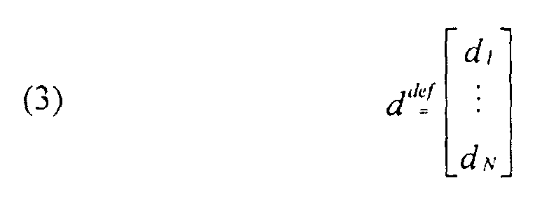
- phase shifts ⁇ i can be measured, the roll-overs m i and the angle of arrival ⁇ are unknown.
- a Diophantine algorithm is used that is based upon a single noisy snapshot (observation). Diophantine computations are discussed in detail in Number Theory and Its History , by Oystein Ore, Dover Publications Inc., New York, 1988, hereby incorporated by reference.
- the algorithm first estimates the roll-over m N corresponding to the largest baseline d N and uses that estimate to derive an estimate for the angle of arrival ⁇ . Note that although finding the roll-over associated with the largest baseline is discussed, it is possible to find the roll-overs associated with all the other baselines in a similar manner. Using the different roll-overs would lead to different estimates of the same angle-of-arrival. These estimates could be combined using weighted averaging to obtain a single improved estimate. Thus, the present invention contemplates the possibility of determining more than one roll-over.
- a multiple -d 2 m of the first row of A can be added to the second row to obtain a new row, all of whose elements are multiples of d 4 . Because adding a multiple of one row to another does not alter the determinant, after factoring d 4 from the modified second row, the new determinant is d 4 2 . Similarly modifying the third row reduces the determinant to d 4 , after which we can replace one of the rows with its negative to change the sign of the determinant.
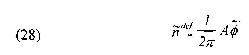
- n Given the phase vector ⁇ , n can be computed as in equation (18) and then used to find the value of the first term in equation (22). Although the value of the second term is unknown, it is an integer multiple of d N , say pd N .
- the range of possible values for p is limited, as replacing i by N in equation (1) and using the fact that
- Fig 1b The operations of the Diophantine algorithm are summarized in Fig 1b.
- This result may be adjusted to correct for calibration error, then augmented or decreased by 2 ⁇ if needed so that the adjusted phase difference, ⁇ i , lies within - ⁇ and ⁇ .
- the roll-over, m N is then calculated as previously described.
- the frequency of the signal impinging on the array is estimated by measuring the change in phase which occurs at element N over a small time interval.
- the change in phase divided by the length of the time interval is an estimate of the frequency in radians.
- Implementation of the Diophantine algorithm is largely independent of frequency, as the frequency value only appears in a single multiplication. In contrast, algorithms such as maximum likelihood might require an entire manifold of steering vectors to be recalculated when the frequency changes.
- the Diophantine algorithm uses a look-up table to invert the arcsine. The result is an estimate of the angle of arrival. Note that a bound check is applied to the table input; if the input has magnitude larger than unity, a detectable ambiguity has occurred and the angle estimate is declared invalid.
- a noisy version of ⁇ must be employed in the algorithm. Because of the noise, may not contain integer elements. However, simply rounding each element to the nearest integer yields a vector nint ( ⁇ ) which can be substituted for n in equation (25). Similarly replacing ⁇ N by , an estimate of m N , , is thereby obtained. If there is a difference between m N and , it is referred to as an ambiguity error.
- the ambiguity error is detectable if the estimated angle of arrival as set forth in equation (27) is meaningless because the argument of the arcsine has magnitude exceeding unity. Otherwise, the ambiguity error is undetectable. Note that all angle of arrival estimation algorithms, including the Diophantine algorithm, can generate erroneous estimates when noise corrupts the measured data.
- the performance of the Diophantine algorithm is compared against that of maximum likelihood in the following two examples, in each of which the azimuth was selected with uniform probability over the range (-90, 90) degrees in 10,000 trials.
- the performance of the Diophantine algorithm was not averaged over trials in which a detectable ambiguity error occurred, as these errors were automatically recognized and discarded.
- the maximum likelihood algorithm could also be modified to reject estimates, based on an estimate of the SNR and on the relative heights of the peaks of the "spectrum" 10 log 10 ⁇
- both the Diophantine algorithm and the maximum likelihood algorithm have comparable performance.
- the former algorithm requires only about 16 multiplications per simulation trial, while the latter requires (at an SNR of 20 dB) about 200 multiplications per simulation trial in the first example and about 900 in the second example to attain the maximum achievable accuracy.
- These large numbers of multiplications could be avoided by the maximum likelihood algorithm only by sacrificing angular estimation accuracy or by employing large, memory-intensive look-up tables.
- the Diophantine algorithm can produce erroneous estimates when noise corrupts the measured phases.
- noise can cause the Diophantine algorithm to incorrectly estimate the roll-over m N .
- Such an error which has been referred to above as an ambiguity error, will either result in an obviously meaningless estimate of the angle of arrival (in which case the ambiguity error is said to be “detectable”) or a grossly inaccurate estimate (in which case the ambiguity error is said to be "undetectable”).
- an approximate formula is derived which expresses an upper bound on the probability of ambiguity error as a function of the matrix A, which in turn must be chosen based on the element locations.
- This formula can be used to evaluate different array configurations and choices of the matrix A and to select from among them so as to ensure a small probability of ambiguity error. It should be understood that many of the assumptions or approximations (such as the phase errors having a Gaussian distribution) made in the derivation of the formula are not required to complete this analysis, but are merely made in order to simplify the calculations. Thus, there are many obvious extensions of this analysis.
- the N-variate integral can be expressed as the product of N separate integrals and where "erf" denotes the well-known error function.
Landscapes
- Physics & Mathematics (AREA)
- Engineering & Computer Science (AREA)
- General Physics & Mathematics (AREA)
- Radar, Positioning & Navigation (AREA)
- Remote Sensing (AREA)
- Variable-Direction Aerials And Aerial Arrays (AREA)
- Radar Systems Or Details Thereof (AREA)
Abstract
Description










Claims (10)
- A linear interferometer for intercepting and determining the angle of arrival of intercepted pulses comprising:wherein said angle of arrival is determined as a Diophantine function.a reference antenna;a plurality of N antennas, colinearly aligned with said reference antenna forming a one dimensional interferometer, the spacing of said antennas relative to the reference antenna selected to be the product of a reference length ξ and a baseline di, where {di, i=1 to N-1} are relatively prime and di, dN is relatively prime for some i in the range 1<=i<N; andmeans for computing the angle of arrival of intercepted pulses at said antennas,
- The linear as recited in claim 1, wherein the reference length is constrained to λ/2 or less.
- The linear as recited in claim 1, wherein the angle of arrival is constrained to be -π/2 ≤ < π/2.
- The linear as recited in claim 1, wherein the number of real multiplications to determine the angle of arrival is N2, where N is the number of said plurality of antenna elements.
- A linear interferometer for determining the angle of arrival of intercepted pulses comprising:a reference antenna;a plurality of N antennas; said reference antenna and said N antennas colinearly disposed and initially spaced apart as a function of a reference length and a baseline di, where {di, i=1 to N-1} are relatively prime, and subsequently spaced apart to optimize the reduction of the probability of ambiguity on subsequent angle of arrival measurements; andmeans for computing the angle of arrival of intercepted pulses.
- The linear interferometer as recited in claim 5, wherein said angle of arrival is a function of the phase shift i at each of the antennas and the phase roll-overs mi wherein errors in the roll-over mi result in ambiguity errors in the angle of arrival .
- The linear interferometer as recited in claim 6, wherein the phase roll-over mN is a function of A/2π, where the is the phase shift, and A is a matrix, where Ad = 0, where the ith element of d, i=1,...,N, is di.
- The linear interferometer as recited in claim 7, wherein the quantity A/2π is rounded to the nearest integer value.
- A method for estimating the angle of arrival of an intercepted pulse comprising the steps of:(a) providing a linear array of antenna elements wherein N+1 denotes the number of elements;(b) locating said antenna elements at coordinates 0, ξ d1, ..., ξ dN, wherein ξ is a reference length not exceeding a half-wavelength (λ/2) at the highest frequency at which the system is to be operated and di is a dimensionless integer for all i and the N-1 numbers {d1, d2, ..., dN-1} are relatively prime and {di, dN} is relatively prime for some i in the range I ≤ i < N and wherein an N-1 by N matrix A with integer values and a vector c with integer values exist such that the calculations:and
 and
and (where nint denotes the nearest integer operator) will generally result in an accurate estimate
 of the true angle of arrival when for i = 1, ..., N, the ith element of the vector
 contains the difference between the noisy, measured phase at the ith array antenna and the noisy, measured phase at the reference antenna (antenna 0).
- The method as recited in claim 10, wherein said antenna elements are positioned so as to approximately minimize the probability of noise causing an ambiguity error, as a function of:where "erf" denotes the well-known error function.

Applications Claiming Priority (2)
| Application Number | Priority Date | Filing Date | Title |
|---|---|---|---|
| US09/633,162 US6377214B1 (en) | 2000-08-04 | 2000-08-04 | Pipelined processing algorithm for interferometer angle of arrival estimation |
| US633162 | 2000-08-04 |
Publications (2)
| Publication Number | Publication Date |
|---|---|
| EP1184675A2 true EP1184675A2 (en) | 2002-03-06 |
| EP1184675A3 EP1184675A3 (en) | 2003-12-10 |
Family
ID=24538527
Family Applications (1)
| Application Number | Title | Priority Date | Filing Date |
|---|---|---|---|
| EP01116727A Withdrawn EP1184675A3 (en) | 2000-08-04 | 2001-07-18 | Pipelined processing algorithm for interferometer angle of arrival estimation |
Country Status (2)
| Country | Link |
|---|---|
| US (1) | US6377214B1 (en) |
| EP (1) | EP1184675A3 (en) |
Cited By (3)
| Publication number | Priority date | Publication date | Assignee | Title |
|---|---|---|---|---|
| WO2004090567A1 (en) * | 2003-04-10 | 2004-10-21 | Selex Sensors And Airborne Systems Limited | Interferometers |
| RU2473958C1 (en) * | 2011-06-08 | 2013-01-27 | Государственное образовательное учреждение высшего профессионального образования Омский государственный университет путей сообщения | Method of registering unit element using fuzzy logic methods |
| CN104459618A (en) * | 2014-10-23 | 2015-03-25 | 郁涛 | Single-station short base line phase difference positioning method relying on virtual observation and distance equivalent exchange |
Families Citing this family (18)
| Publication number | Priority date | Publication date | Assignee | Title |
|---|---|---|---|---|
| US6680691B2 (en) * | 2002-05-13 | 2004-01-20 | Honeywell International Inc. | Methods and apparatus for accurate phase detection |
| US6674397B2 (en) * | 2002-05-13 | 2004-01-06 | Honeywell International Inc. | Methods and apparatus for minimum computation phase demodulation |
| US6950056B2 (en) * | 2002-05-13 | 2005-09-27 | Honeywell International Inc. | Methods and apparatus for determination of a filter center frequency |
| US20030210176A1 (en) * | 2002-05-13 | 2003-11-13 | Hager James R. | Methods and apparatus for resolution of radar range ambiguities |
| US6768469B2 (en) * | 2002-05-13 | 2004-07-27 | Honeywell International Inc. | Methods and apparatus for radar signal reception |
| US6639545B1 (en) * | 2002-05-13 | 2003-10-28 | Honeywell International Inc. | Methods and apparatus to determine a target location in body coordinates |
| US6856279B2 (en) * | 2002-05-13 | 2005-02-15 | Honeywell International Inc. | Methods and apparatus for determining an interferometric angle to a target in body coordinates |
| US6734820B2 (en) * | 2002-05-13 | 2004-05-11 | Honeywell International Inc. | Methods and apparatus for conversion of radar return data |
| US7358898B2 (en) * | 2003-01-31 | 2008-04-15 | Andrew Corporation | Method for calibrating an AOA location system for all frequencies in a frequency hopping signal |
| US7379019B2 (en) * | 2003-01-31 | 2008-05-27 | Andrew Corporation | Method for angle of arrival determination on frequency hopping air interfaces |
| US7405696B2 (en) * | 2003-01-31 | 2008-07-29 | Andrew Corporation | Method for calibrating and AOA location system for frequency hopping air interfaces |
| WO2005069905A2 (en) * | 2004-01-16 | 2005-08-04 | Ghz Tr Corporation | Methods and apparatus for automotive radar sensors |
| US7109909B2 (en) * | 2004-03-11 | 2006-09-19 | Lockheed Martin Corporation | System for establishing an attenuation frequency |
| US8179319B1 (en) * | 2008-12-17 | 2012-05-15 | L-3 Services, Inc. | Adaptive optimization of estimation of the angle of arrival of a signal received by an array of antenna elements |
| FR2999297B1 (en) * | 2012-12-07 | 2015-01-30 | Thales Sa | PASSIVE LOCATION METHOD OF RADAR TRANSMITTERS |
| US10302743B2 (en) * | 2015-06-09 | 2019-05-28 | Raytheon Company | Systems and methods for antenna analysis and validation |
| US10401467B2 (en) * | 2015-08-25 | 2019-09-03 | Huawei Technologies Canada Co., Ltd. | System and method for estimating the direction of arrival of an electromagnetic beam |
| CN115598593B (en) * | 2022-12-14 | 2023-03-21 | 湖南红船科技有限公司 | Equal-length short-baseline high-precision direction-finding positioning method, system, equipment and terminal |
Family Cites Families (16)
| Publication number | Priority date | Publication date | Assignee | Title |
|---|---|---|---|---|
| US3633205A (en) * | 1969-06-30 | 1972-01-04 | Loral Electronics Corp | Wideband interferometer type antenna systems |
| US4541687A (en) | 1983-09-02 | 1985-09-17 | Trw Inc. | Signal processing system and method |
| US4638321A (en) | 1984-06-01 | 1987-01-20 | Eaton Corporation | Unambiguous wide baseline interferometer |
| GB8612753D0 (en) | 1986-05-27 | 1986-09-17 | Tong D A | Direction finding equipment |
| FR2660752B1 (en) | 1987-07-02 | 1992-09-11 | Dassault Electronique | LASER PULSE ANGLE DETECTOR, PARTICULARLY FOR TANKS. |
| US4977365A (en) | 1989-08-17 | 1990-12-11 | The United States Of America As Represented By The Secretary Of The Air Force | Instantaneous frequency measurement (IFM) receiver to measure frequency and angle of arrival (AOA) of multiple signals |
| US5381150A (en) | 1993-05-07 | 1995-01-10 | Trw Inc. | Partial intercept LPI (low probability of intercept) reconnaissance system |
| US5451956A (en) | 1993-08-20 | 1995-09-19 | Trw Inc. | Instantaneous parameter measuring receiver |
| US5457466A (en) * | 1993-09-07 | 1995-10-10 | Litton Systems Inc. | Emitter azimuth and elevation direction finding using only linear interferometer arrays |
| IL111629A (en) | 1993-11-19 | 1999-10-28 | Trw Inc | Parameter encoder architecture |
| DE4425661A1 (en) * | 1994-07-20 | 1996-01-25 | Daimler Benz Aerospace Ag | Large base interferometer direction finder system |
| US5497161A (en) | 1994-10-26 | 1996-03-05 | The United States Of America As Represented By The Secretary Of The Air Force | Angle of arrival (AOA) solution using a single receiver |
| US5572220A (en) | 1995-05-18 | 1996-11-05 | Hughes Aircraft Company | Technique to detect angle of arrival with low ambiguity |
| US5568154A (en) | 1995-05-22 | 1996-10-22 | State Of Israel-Ministry Of Defense Armament Development Authority-Rafael | System and a method for the instantaneous determination of the frequencies and angles of arrival of simultaneously incoming RF signals |
| US5691728A (en) | 1996-03-25 | 1997-11-25 | Trw Inc. | Method and apparatus for bias error reductioon in an N-port modeformer of the butler matrix type |
| US5657027A (en) | 1996-06-02 | 1997-08-12 | Hughes Electronics | Two dimensional interferometer array |
-
2000
- 2000-08-04 US US09/633,162 patent/US6377214B1/en not_active Expired - Lifetime
-
2001
- 2001-07-18 EP EP01116727A patent/EP1184675A3/en not_active Withdrawn
Cited By (6)
| Publication number | Priority date | Publication date | Assignee | Title |
|---|---|---|---|---|
| WO2004090567A1 (en) * | 2003-04-10 | 2004-10-21 | Selex Sensors And Airborne Systems Limited | Interferometers |
| US7026990B2 (en) | 2003-04-10 | 2006-04-11 | Bae Systems, Plc | Interferometer arrangement for unambiguous determination of an angle of incidence of incident electromagnetic radiation |
| EP2977783A1 (en) * | 2003-04-10 | 2016-01-27 | Selex Es Ltd | Interferometers |
| RU2473958C1 (en) * | 2011-06-08 | 2013-01-27 | Государственное образовательное учреждение высшего профессионального образования Омский государственный университет путей сообщения | Method of registering unit element using fuzzy logic methods |
| CN104459618A (en) * | 2014-10-23 | 2015-03-25 | 郁涛 | Single-station short base line phase difference positioning method relying on virtual observation and distance equivalent exchange |
| CN104459618B (en) * | 2014-10-23 | 2020-12-29 | 郁涛 | Single-station short baseline phase difference positioning method by means of virtual observation and distance equivalent exchange |
Also Published As
| Publication number | Publication date |
|---|---|
| EP1184675A3 (en) | 2003-12-10 |
| US6377214B1 (en) | 2002-04-23 |
Similar Documents
| Publication | Publication Date | Title |
|---|---|---|
| US6377214B1 (en) | Pipelined processing algorithm for interferometer angle of arrival estimation | |
| Weiss et al. | Array shape calibration using sources in unknown locations-a maximum likelihood approach | |
| US20110208481A1 (en) | Extended range interferometric methods and systems | |
| US7268728B1 (en) | Moving transmitter correlation interferometer geolocation | |
| US7576682B1 (en) | Method and system for radar target detection and angle estimation in the presence of jamming | |
| CA3041907A1 (en) | Direction of arrival estimation | |
| JP6778336B2 (en) | RF signal arrival angle determination method and system | |
| SE511952C2 (en) | A SAR radar system | |
| Liao et al. | Direction-of-arrival estimation in subarrays-based linear sparse arrays with gain/phase uncertainties | |
| KR101796472B1 (en) | Radar apparatus and DOA estimation method using the same | |
| Singh et al. | Near field targets localization using bistatic MIMO system with spherical wavefront based model | |
| EP1682923B1 (en) | Method for localising at least one emitter | |
| Molaei et al. | Efficient clustering of non-coherent and coherent components regardless of sources’ powers for 2D DOA estimation | |
| Durrani et al. | Eigenfilter approaches to adaptive array processing | |
| US7026990B2 (en) | Interferometer arrangement for unambiguous determination of an angle of incidence of incident electromagnetic radiation | |
| Vaidyanathan et al. | Sparse arrays: fundamentals | |
| Wu et al. | Performance characterization of sparse array angle finding algorithms for automotive radars | |
| JP3647621B2 (en) | Radio direction detector | |
| Dakulagi | Single snapshot 2D-DOA estimation in wireless location system | |
| CN119001660B (en) | A method, device and medium for deambiguating uniform circular array spatial spectrum direction finding | |
| CN113093111A (en) | Method and system for demodulating two-dimensional coherent signals by uniform circular array based on compressed sensing and genetic algorithm | |
| CN112965026B (en) | A DOA array element spacing setting method with a priori positioning angle range | |
| Wang et al. | Signal and array processing techniques for RFID readers | |
| Güngör et al. | Hardware-Efficient Direction of Arrival Estimation using Compressive Sensing | |
| Li et al. | The Phase Fractional Lower-Order Moment Based DPD Algorithm of Non-circular Sources for Nested Array Under Impulsive Noise |
Legal Events
| Date | Code | Title | Description |
|---|---|---|---|
| PUAI | Public reference made under article 153(3) epc to a published international application that has entered the european phase |
Free format text: ORIGINAL CODE: 0009012 |
|
| AK | Designated contracting states |
Kind code of ref document: A2 Designated state(s): AT BE CH CY DE DK ES FI FR GB GR IE IT LI LU MC NL PT SE TR |
|
| AX | Request for extension of the european patent |
Free format text: AL;LT;LV;MK;RO;SI |
|
| PUAL | Search report despatched |
Free format text: ORIGINAL CODE: 0009013 |
|
| RAP1 | Party data changed (applicant data changed or rights of an application transferred) |
Owner name: NORTHROP GRUMMAN CORPORATION |
|
| RAP1 | Party data changed (applicant data changed or rights of an application transferred) |
Owner name: NORTHROP GRUMMAN CORPORATION |
|
| AK | Designated contracting states |
Kind code of ref document: A3 Designated state(s): AT BE CH CY DE DK ES FI FR GB GR IE IT LI LU MC NL PT SE TR |
|
| AX | Request for extension of the european patent |
Extension state: AL LT LV MK RO SI |
|
| STAA | Information on the status of an ep patent application or granted ep patent |
Free format text: STATUS: THE APPLICATION IS DEEMED TO BE WITHDRAWN |
|
| 18D | Application deemed to be withdrawn |
Effective date: 20040203 |