EP1184285A2 - Unit for transferring articles - Google Patents
Unit for transferring articles Download PDFInfo
- Publication number
- EP1184285A2 EP1184285A2 EP01118844A EP01118844A EP1184285A2 EP 1184285 A2 EP1184285 A2 EP 1184285A2 EP 01118844 A EP01118844 A EP 01118844A EP 01118844 A EP01118844 A EP 01118844A EP 1184285 A2 EP1184285 A2 EP 1184285A2
- Authority
- EP
- European Patent Office
- Prior art keywords
- unit
- guide member
- respect
- guide
- support
- Prior art date
- Legal status (The legal status is an assumption and is not a legal conclusion. Google has not performed a legal analysis and makes no representation as to the accuracy of the status listed.)
- Granted
Links
Images



Classifications
-
- B—PERFORMING OPERATIONS; TRANSPORTING
- B65—CONVEYING; PACKING; STORING; HANDLING THIN OR FILAMENTARY MATERIAL
- B65B—MACHINES, APPARATUS OR DEVICES FOR, OR METHODS OF, PACKAGING ARTICLES OR MATERIALS; UNPACKING
- B65B57/00—Automatic control, checking, warning, or safety devices
- B65B57/10—Automatic control, checking, warning, or safety devices responsive to absence, presence, abnormal feed, or misplacement of articles or materials to be packaged
- B65B57/14—Automatic control, checking, warning, or safety devices responsive to absence, presence, abnormal feed, or misplacement of articles or materials to be packaged and operating to control, or stop, the feed of articles or material to be packaged
-
- B—PERFORMING OPERATIONS; TRANSPORTING
- B65—CONVEYING; PACKING; STORING; HANDLING THIN OR FILAMENTARY MATERIAL
- B65B—MACHINES, APPARATUS OR DEVICES FOR, OR METHODS OF, PACKAGING ARTICLES OR MATERIALS; UNPACKING
- B65B19/00—Packaging rod-shaped or tubular articles susceptible to damage by abrasion or pressure, e.g. cigarettes, cigars, macaroni, spaghetti, drinking straws or welding electrodes
- B65B19/02—Packaging cigarettes
- B65B19/04—Arranging, feeding, or orientating the cigarettes
-
- B—PERFORMING OPERATIONS; TRANSPORTING
- B65—CONVEYING; PACKING; STORING; HANDLING THIN OR FILAMENTARY MATERIAL
- B65B—MACHINES, APPARATUS OR DEVICES FOR, OR METHODS OF, PACKAGING ARTICLES OR MATERIALS; UNPACKING
- B65B19/00—Packaging rod-shaped or tubular articles susceptible to damage by abrasion or pressure, e.g. cigarettes, cigars, macaroni, spaghetti, drinking straws or welding electrodes
- B65B19/28—Control devices for cigarette or cigar packaging machines
- B65B19/32—Control devices for cigarette or cigar packaging machines responsive to incorrect grouping of articles or to incorrect filling of packages
Definitions
- the present invention relates to a unit for transferring articles.
- the present invention relates to a unit for transferring groups of cigarettes on a cigarette packaging machine, to which the following description refers purely by way of example.
- Cigarette packaging machines provide for forming groups of normally twenty cigarettes, and for packaging the groups in packaging material.
- the cigarettes are housed in bulk inside a hopper having a number of substantially vertical outlets, down which the cigarettes are fed by force of gravity on to a plate on which a group of cigarettes is formed.
- the machine comprises a transfer unit having a pocket conveyor for feeding the groups in a given first direction; a pusher for each outlet, to expel the groups of cigarettes from the hopper outlet in a second direction perpendicular to the first direction; and, for each outlet, a guide located between the outlet and the conveyor and aligned with the hopper outlet to guide the groups of cigarettes into a conveyor pocket along a path parallel to the second direction.
- the conveyor cyclically arrests a pocket at each guide, and, while the pockets are stationary, the pushers transfer respective groups of cigarettes through the respective guides from the outlets to the pockets. Once the groups are transferred from the outlets to the respective pockets, the pockets are fed forward in the first direction to transfer the groups to packaging wheels on the machine to wrap the groups in respective sheets of packaging material to form packets of cigarettes.
- the forward movement of the pocket in the first direction subjects the group to shearing stress, which is opposed strongly by the group of cigarettes, on account of the guide having compressed the cigarettes together, so that the group acts substantially as a single body and is resistant enough to cause failure of the weaker or less firmly connected structural elements.
- the worst damage is caused to the pocket, which breaks away from the conveyor.
- a unit for transferring articles, in particular groups of cigarettes comprising a conveyor having at least one pocket for housing the articles and for feeding the articles in a first direction; and a guide for guiding the articles into a said pocket along a transfer path in a second direction crosswise to said first direction; and the unit being characterized by comprising a safety device comprising a guide member adjacent to the conveyor and movable between a work position defining part of the transfer path, and an emergency position remote from the transfer path; and a first actuator for setting the guide member to the emergency position when the articles transmit to the guide member a force over and above a threshold value.
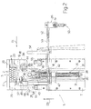
- Machine 1 comprises a frame T supporting a hopper 4 for receiving cigarettes 2 in bulk and forming groups 3; and a transfer unit 5 for transferring groups 3.
- Hopper 4 comprises a number of outlets 6, each of which comprises feed channels 7 for cigarettes 2, and a bottom supporting plate 8 for arresting cigarettes 2.
- the cigarettes 2 contacting plate 8 form a bottom layer 9, on top of which are formed successive layers 9 of cigarettes; and a group 3 of cigarettes 2 comprises three superimposed layers 9, which are subsequently compressed to compact cigarettes 2 as far as possible.
- Transfer unit 5 comprises a pusher 10 located at each outlet 6; a guide 11 located on the opposite side of outlet 6 to pusher 10; and a conveyor 12, in turn comprising a number of pockets 13 fed in a direction D1.
- Pusher 10 comprises a rod 14; and fingers 15, which are inserted inside the various channels 7 to expel a group 3 from outlet 6 and transfer group 3 through guide 11 into a pocket 13 arrested in front of guide 11.
- Each pusher 10 is operated independently of the other pushers 10 by a respective linear actuator 16, which moves pusher 10 back and forth in a direction D2 perpendicular to direction D1.
- guide 11 comprises a tubular sleeve 17 adjacent to hopper 4; and a guide member 18 adjacent to conveyor 12.
- Tubular sleeve 17 comprises a bottom wall 19; a top wall 20 parallel to bottom wall 19; and two lateral walls 21 perpendicular to walls 19 and 20 and converging in direction D2, from outlet 6 towards conveyor 12, to form a tapering channel 22 for compacting cigarettes 2 in each group 3 fed through guide 11.
- Guide member 18 defines two parallel, facing lateral walls 23, which, in use, are adjacent to walls 19 and 20 and project towards conveyor 12 with respect to lateral walls 21.
- Bottom wall 19 of sleeve 17 projects with respect to lateral walls 21 towards hopper 4, and forms a supporting surface for cigarettes 2 together with plate 8.
- Transfer unit 5 comprises, for each guide 11, a tipping device 24 connecting sleeve 17 to frame T; and a safety device 25 comprising guide member 18 of guide 11 and fitted to tipping device 24.
- Unit 5 also comprises a reset device 26 common to all of guides 11.
- Tipping device 24 comprises a rod 27, which is located beneath sleeve 17 and is connected to a point along bottom wall 19 of sleeve 17 by a hinge 28 having an axis parallel to direction D1, and to a point on frame T by a hinge 29 also having an axis parallel to direction D1.
- Device 24 also comprises a slide 30, which is fitted to slide along a guide 31 integral with frame T and extending in a vertical direction D3, and is connected to a point along bottom wall 19 of sleeve 17 by a hinge 32 having an axis parallel to direction D1.
- Device 24 also comprises an actuator 33 extending along guide 31 and having one end fixed to frame T and the other end fixed to slide 30.
- safety device 25 also comprises a spring 34; a slot 35 housing spring 34 and formed in slide 30; and two teeth 36 and 37 integral with slide 30 and guide member 18 respectively.
- guide member 18 comprises a central body 38, from which the two walls 23 project upwards, and from which projects downwards a projection 39 connected by a pin 40 to a slide 41 running in a guide 42 formed on slide 30. Projection 39 and slide 41 are connected by pin 40, which allows guide member 18 to oscillate about an axis 43 of pin 40 parallel to direction D2.
- Guide member 18 supports two rollers 44 and 45 located on opposite sides of slide 30 and loosely engaging respective guides 46 and 47 formed in slide 30 and which restrict the oscillation of guide member 18 to a few degrees.
- Each guide member 18 comprises a bottom surface 48 of central body 38; and an elongated slot 49 formed in central body 38 and which comes out at surface 48.
- reset device 26 comprises a linear actuator 50 having one end integral with frame T and the other end hinged to a crank 51, which rotates with respect to frame T about an axis 52 parallel to direction D1, and is integral with a shaft 53 extending parallel to axis 52 at each safety device 25.
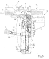
- Reset device 26 comprises a number of rods 54, each of which is located at a respective guide member 18, is integral with shaft 53, and rotates about axis 52 between a rest position engaging slot 49 as shown in Figure 4, and a work position resting against surface 48 to brace guide member 18 as shown in Figure 6.
- Unit 5 also comprises rubber pads 55 for cushioning the impact of guide member 18 when withdrawn by spring 34.
- groups 3 of cigarettes are transferred by pushers 10 from respective outlets 6 to pockets 13 through guide 11 along a transfer path P parallel to direction D2.
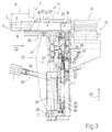
- sleeve 17 and guide member 18 are in the work position ( Figure 3) and together define guide 11 and path P.
- the group 3 of cigarettes may assume the position shown in the central outlet in Figure 1, i.e. astride guide 11 and pocket 13, so that, when conveyor 12 feeds pockets 13 in direction D1, group 3 reacts with a force opposing motion and exerts a force in direction D1 on wall 23 of guide member 18.
- transfer unit 5 is set to the work position, teeth 36 and 37 are mutually engaged, and rods 54 are located beneath and aligned with respective slots 49.
- guide member 18 is lowered by spring 34 into the Figure 4 emergency position in which rod 54 engages the slot 49 of the released guide member 18, and sleeve 17 is set to the work position.
- slide 41 is located at the bottom of respective guide 42.
- actuator 33 of tipping device 24 is operated to move slide 30 upwards in direction D3 and tip sleeve 17 about hinges 28 and 29 into a maintenance position.
- guide member 18 remains in the same position with respect to slide 30, but changes position with respect to conveyor 12 and is set above the work position. In other words, the upward movement of slide 30 is greater than the downward movement of guide member 18 with respect to slide 30.
- actuator 50 of reset device 26 is operated to set rods 54 to the respective work positions. The rod 54 engaging slot 49 is released by the upward movement of member 18 together with slide 30, and is rotated about axis 52 into the work position.
- teeth 36 and 37 have respective beveled ends, so that tooth 37, on contacting tooth 36 as slide 30 moves down, produces a clockwise rotation about axis 43 in Figure 2 to clear tooth 36, and is then restored to the interference position by rod 54.
- tooth 37 rests on tooth 36 and is once more held against tooth 36 by spring 34.
- Actuator 50 is then withdrawn and rods 54 are again positioned at respective slots 49.
- the unit described has the advantage of avoiding any stoppage of the packaging machine in the event of incomplete transfer of a group, and of enabling the cigarettes clogging the guide or hopper outlet to be removed easily without stopping the machine, which continues operating to a lesser degree as the operator repairs the pusher and removes the cigarettes clogging the outlet and/or guide.
Landscapes
- Engineering & Computer Science (AREA)
- Mechanical Engineering (AREA)
- Wrapping Of Specific Fragile Articles (AREA)
- Control And Other Processes For Unpacking Of Materials (AREA)
- Vending Machines For Individual Products (AREA)
- Supplying Of Containers To The Packaging Station (AREA)
- Manufacturing Of Cigar And Cigarette Tobacco (AREA)
Abstract
Description
Claims (14)
- A unit for transferring articles, in particular groups (3) of cigarettes; the unit (5) comprising a conveyor (12) having at least one pocket (13) for housing the articles (3) and for feeding the articles (3) in a first direction (D1); and a guide (11) for guiding the articles (3) into a said pocket (13) along a transfer path (P) in a second direction (D2) crosswise to said first direction (D1); and the unit (5) being characterized by comprising a safety device (25) comprising a guide member (18) adjacent to the conveyor (12) and movable between a work position defining part of the transfer path (P), and an emergency position remote from the transfer path (P); and a first actuator (34) for setting the guide member (18) to the emergency position when the articles (3) transmit to the guide member (18) a force over and above a threshold value.
- A unit as claimed in Claim 1, characterized in that said guide member (18), in said work position, is set to a position of equilibrium with respect to a support (30); said force altering said position of equilibrium.
- A unit as claimed in Claim 1 or 2, characterized in that said force comprises at least one component in the first direction (D1).
- A unit as claimed in Claims 2 and 3, characterized in that said support (30) comprises a first tooth (36), and said guide member (18) comprises a second tooth (37) engaging the first tooth (36) in said position of equilibrium.
- A unit as claimed in Claim 4, characterized in that said guide member (18) is connected to said support (30) by said first actuator (34); said first actuator (34) pushing the first and the second tooth (36, 37) against each other, and withdrawing said guide member (18) into said emergency position.
- A unit as claimed in Claim 4 or 5, characterized in that said guide member (18) is movable, with respect to said support (30), in a third direction (D3) perpendicular to the first and second direction (D1, D2), and rotates with respect to said support (30) about an axis (43) parallel to said second direction (D2); said force rotating said guide member (18) with respect to said support (30) to release said second tooth (37) from said first tooth (36).
- A unit as claimed in Claim 6, characterized in that said guide member (18) is mounted to rotate about said axis (43) with respect to a first slide (41) sliding with respect to said support (30); said first actuator (34) being a spring (34) connecting said first slide (41) to said support (30).
- A unit as claimed in Claim 6 or 7, characterized in that said guide member (18) comprises stops (44, 45) for restricting rotation of the guide member (18) with respect to the support (30).
- A unit as claimed in any one of Claims 1 to 8, characterized in that said guide member (18) comprises two lateral walls (23) forming part of said guide (11) in said work position; said lateral walls (23) being adjacent to said conveyor (12).
- A unit as claimed in Claim 9, characterized in that said guide (11) comprises a sleeve (17); said lateral walls (23) being complementary to said sleeve (17) to form said guide (11).
- A unit as claimed in Claim 10, characterized in that said sleeve (17) can be tipped, by a tipping device (24), between a work position wherein said sleeve (17) partly defines the transfer path (P), and a maintenance position; said tipping device (24) comprising said support (30).
- A unit as claimed in Claim 11, characterized in that said support (30) is a second slide (30); said second slide (30) being movable in said third direction (D3) with respect to said conveyor (12) to set said sleeve (17) to said work position and to said maintenance position; said tipping device (24) comprising a second actuator (33) for changing the position of said second slide (30) with respect to said conveyor (12).
- A unit as claimed in Claim 12, characterized by comprising a reset device (26) comprising a supporting member (54) movable between a rest position and a work position to keep said guide member (18) in a fixed position with respect to said conveyor (12) while the position of said second slide (30) with respect to said conveyor (12) is changed by said second actuator (33) to restore said sleeve (17) to the work position.
- A unit as claimed in any one of Claims 1 to 13, characterized by comprising a number of guides (11), and a safety device (25) for each guide (11).
Applications Claiming Priority (2)
| Application Number | Priority Date | Filing Date | Title |
|---|---|---|---|
| IT2000BO000495A ITBO20000495A1 (en) | 2000-08-16 | 2000-08-16 | ARTICLE TRANSFER UNIT. |
| ITBO000495 | 2000-08-16 |
Publications (3)
| Publication Number | Publication Date |
|---|---|
| EP1184285A2 true EP1184285A2 (en) | 2002-03-06 |
| EP1184285A3 EP1184285A3 (en) | 2002-12-18 |
| EP1184285B1 EP1184285B1 (en) | 2004-05-26 |
Family
ID=11438685
Family Applications (1)
| Application Number | Title | Priority Date | Filing Date |
|---|---|---|---|
| EP01118844A Expired - Lifetime EP1184285B1 (en) | 2000-08-16 | 2001-08-13 | Unit for transferring articles |
Country Status (7)
| Country | Link |
|---|---|
| US (1) | US6543603B2 (en) |
| EP (1) | EP1184285B1 (en) |
| AT (1) | ATE267742T1 (en) |
| DE (1) | DE60103464T2 (en) |
| ES (1) | ES2218318T3 (en) |
| IT (1) | ITBO20000495A1 (en) |
| TR (1) | TR200401524T4 (en) |
Cited By (2)
| Publication number | Priority date | Publication date | Assignee | Title |
|---|---|---|---|---|
| ITBO20110127A1 (en) * | 2011-03-16 | 2012-09-17 | Gd Spa | MACHINE FOR FORMATION AND BOXING OF CIGARETTE GROUPS. |
| ITUA20162281A1 (en) * | 2016-04-04 | 2017-10-04 | Gima Tt S P A | TRANSFER OF ORGANIZED GROUPS OF SMOKE ITEMS, APPARATUS AND METHOD FOR THE SUPPLY AND TRAINING OF ORGANIZED GROUPS OF SMOKE ARTICLES INCLUDING THE TRANSFER DEVICE |
Families Citing this family (5)
| Publication number | Priority date | Publication date | Assignee | Title |
|---|---|---|---|---|
| ITBO20010298A1 (en) * | 2001-05-14 | 2002-11-14 | Gd Spa | METHOD FOR THE CREATION OF SOFT-TYPE CIGARETTE PACKAGES |
| GB2438591B (en) * | 2006-06-01 | 2011-07-13 | Cilag Gmbh Int | Injection device |
| CN102476712B (en) * | 2010-11-25 | 2013-05-22 | 中国科学院沈阳自动化研究所 | The smoke access channel of the packaging machine single cigarette detection and rejection equipment |
| IT202100019427A1 (en) * | 2021-07-22 | 2023-01-22 | Sasib Spa | Packaging machine and method of packaging truncated cone-shaped tubular elements, in particular from the tobacco industry |
| CN119305797B (en) * | 2024-11-19 | 2025-10-24 | 上海烟草机械有限责任公司 | Cigarette feeding device and control method thereof |
Family Cites Families (8)
| Publication number | Priority date | Publication date | Assignee | Title |
|---|---|---|---|---|
| IT1108245B (en) * | 1978-06-01 | 1985-12-02 | Gd Spa | FEEDING AND CONTROL DEVICE FOR LAYERS OF CIGARETTES IN PACKAGING MACHINES FOR CIGARETTES IN PACKAGES |
| DE3527742C2 (en) * | 1985-08-02 | 1996-06-13 | Focke & Co | Device for conveying groups of cigarettes |
| GB8718085D0 (en) * | 1987-07-30 | 1987-09-03 | Molins Plc | Forming groups of rod-like articles |
| IT1285459B1 (en) * | 1996-02-19 | 1998-06-08 | Gd Spa | CIGARETTE GROUPS FORMING UNIT |
| DE19703493A1 (en) * | 1997-01-31 | 1998-08-06 | Topack Verpacktech Gmbh | Device for transferring a layer of cigarettes |
| DE19746141A1 (en) * | 1997-10-18 | 1999-04-22 | Topack Verpacktech Gmbh | Method and device for wrapping articles of the tobacco processing industry into packaging material blanks |
| IT1304443B1 (en) * | 1998-12-22 | 2001-03-19 | Gd Spa | CIGARETTE GROUP FORMING DEVICE. |
| EP1108650A1 (en) * | 1999-12-15 | 2001-06-20 | TOPACK Verpackungstechnik GmbH | Method and device for making and transferring groups of cigarettes in a plural line packaging machine |
-
2000
- 2000-08-16 IT IT2000BO000495A patent/ITBO20000495A1/en unknown
-
2001
- 2001-08-10 US US09/927,990 patent/US6543603B2/en not_active Expired - Fee Related
- 2001-08-13 EP EP01118844A patent/EP1184285B1/en not_active Expired - Lifetime
- 2001-08-13 DE DE60103464T patent/DE60103464T2/en not_active Expired - Lifetime
- 2001-08-13 AT AT01118844T patent/ATE267742T1/en not_active IP Right Cessation
- 2001-08-13 ES ES01118844T patent/ES2218318T3/en not_active Expired - Lifetime
- 2001-08-13 TR TR2004/01524T patent/TR200401524T4/en unknown
Cited By (9)
| Publication number | Priority date | Publication date | Assignee | Title |
|---|---|---|---|---|
| ITBO20110127A1 (en) * | 2011-03-16 | 2012-09-17 | Gd Spa | MACHINE FOR FORMATION AND BOXING OF CIGARETTE GROUPS. |
| EP2500284A1 (en) * | 2011-03-16 | 2012-09-19 | G.D S.p.A. | Machine for forming and boxing groups of cigarettes |
| CN102673824A (en) * | 2011-03-16 | 2012-09-19 | 吉地股份公司 | Machine for forming and boxing groups of cigarettes |
| CN102673824B (en) * | 2011-03-16 | 2015-11-25 | 吉地股份公司 | For the formation of group, of cigarettes and the machine of being cased |
| ITUA20162281A1 (en) * | 2016-04-04 | 2017-10-04 | Gima Tt S P A | TRANSFER OF ORGANIZED GROUPS OF SMOKE ITEMS, APPARATUS AND METHOD FOR THE SUPPLY AND TRAINING OF ORGANIZED GROUPS OF SMOKE ARTICLES INCLUDING THE TRANSFER DEVICE |
| WO2017174528A1 (en) * | 2016-04-04 | 2017-10-12 | Gima Tt S.P.A. | Transfer device for organized groups of smoking articles, apparatus and method to feed and form organized groups of smoking articles comprising said transfer device |
| WO2017174531A1 (en) * | 2016-04-04 | 2017-10-12 | Gima Tt S.P.A. | Method and apparatus to feed and form organized groups of smoking articles |
| US10946994B2 (en) | 2016-04-04 | 2021-03-16 | I.M.A. Industria Macchine Automatche S.P.A. | Transfer device for organized groups of smoking articles, apparatus and method to feed and form organized groups of smoking articles comprising said transfer device |
| US10954012B2 (en) | 2016-04-04 | 2021-03-23 | I.M.A. Industria Macchine Automatiche S.P.A. | Method and apparatus to feed and form organized groups of smoking articles |
Also Published As
| Publication number | Publication date |
|---|---|
| ES2218318T3 (en) | 2004-11-16 |
| US6543603B2 (en) | 2003-04-08 |
| TR200401524T4 (en) | 2004-08-23 |
| DE60103464T2 (en) | 2005-06-16 |
| DE60103464D1 (en) | 2004-07-01 |
| EP1184285A3 (en) | 2002-12-18 |
| ATE267742T1 (en) | 2004-06-15 |
| ITBO20000495A0 (en) | 2000-08-16 |
| ITBO20000495A1 (en) | 2002-02-16 |
| EP1184285B1 (en) | 2004-05-26 |
| US20020020606A1 (en) | 2002-02-21 |
Similar Documents
| Publication | Publication Date | Title |
|---|---|---|
| EP0168548A2 (en) | Product supply system for accumulation packaging machine | |
| EP1184285B1 (en) | Unit for transferring articles | |
| ITBO960077A1 (en) | APPARATUS FOR AUTOMATIC, CONTINUOUS, RAPID AND PRECISE WEIGHING OF SMALL PRODUCTS, ESPECIALLY OF GELATIN CAPSULES | |
| EP1086895A3 (en) | Device for feeding tablets and the like to a packaging machine | |
| ITRM940540A1 (en) | "TWISTING WINDING MACHINE" | |
| US4319861A (en) | Magazine-type cigarette feeding apparatuses for a cigarette packaging machine | |
| CA1040521A (en) | Device to check and discard lengths of wrapping material (foil) in very high speed packet cigarette packers | |
| EP1262428B1 (en) | Package stacking apparatus | |
| EP1020357B1 (en) | Method of forming groups of cigarettes on a cigarette packing machine | |
| US4262468A (en) | Device for spacing apart objects conveyed through an operation-performing machine | |
| ITBO950450A1 (en) | APPARATUS FOR PACKAGING PRODUCTS INSIDE CASES | |
| ITBO20060194A1 (en) | APPARATUS FOR FORMING A CONTINUOUS AND FALLED FLOW OF PAPER ROLLS GROUPS AND OTHER PRODUCTS APPROPRIATELY ORIENTED, INITALLY SINGLE OR PRE-PACKAGED, TOWARDS A CONTINUOUS AND HIGH-PRODUCTION OPERATING MACHINE, SUCH AS A BAGER | |
| SU847908A3 (en) | Device for supply and distribution of cigarette boxes to racking machine | |
| EP1795076B1 (en) | A device and procedure for the batch transfer of tobacco products | |
| EP1623940B1 (en) | A unit for conveying products | |
| CN106697400B (en) | Automatic box arranging device for box packaging machine and implementation method thereof | |
| US7941992B2 (en) | Method and unit for feeding products to a group-forming unit | |
| EP1101701B1 (en) | Cigar feed unit | |
| ITGE940080A1 (en) | PACKAGING MACHINE FOR DELICATE ASTIFORM PRODUCTS, IN PARTICULAR FOR CIGARETTES. | |
| US4129205A (en) | Method and assembly for feeding articles | |
| JP2668263B2 (en) | Device for filling goods into PTP pocket | |
| EP1808376B1 (en) | Method and assembly for separating opening devices supplied jointly in the form of a sheet and applied individually to respective packages of pourable food products | |
| US4690265A (en) | Packet handling apparatus | |
| US5222606A (en) | Device for feeding cigarettes to the wrapping line of a packaging machine | |
| IT202000013987A1 (en) | MACHINE FOR PACKAGING GROUPS OF TISSUE PRODUCTS AND METHOD OF CHECKING CONFORMITY OF LAYERS OF GROUPS OF TISSUE PRODUCTS |
Legal Events
| Date | Code | Title | Description |
|---|---|---|---|
| PUAI | Public reference made under article 153(3) epc to a published international application that has entered the european phase |
Free format text: ORIGINAL CODE: 0009012 |
|
| AK | Designated contracting states |
Kind code of ref document: A2 Designated state(s): AT BE CH CY DE DK ES FI FR GB GR IE IT LI LU MC NL PT SE TR |
|
| AX | Request for extension of the european patent |
Free format text: AL;LT;LV;MK;RO;SI |
|
| PUAL | Search report despatched |
Free format text: ORIGINAL CODE: 0009013 |
|
| AK | Designated contracting states |
Kind code of ref document: A3 Designated state(s): AT BE CH CY DE DK ES FI FR GB GR IE IT LI LU MC NL PT SE TR |
|
| AX | Request for extension of the european patent |
Free format text: AL;LT;LV;MK;RO;SI |
|
| RAP1 | Party data changed (applicant data changed or rights of an application transferred) |
Owner name: G.D SOCIETA' PER AZIONI |
|
| 17P | Request for examination filed |
Effective date: 20030612 |
|
| AKX | Designation fees paid |
Designated state(s): AT BE CH CY DE DK ES FI FR GB GR IE IT LI LU MC NL PT SE TR |
|
| GRAP | Despatch of communication of intention to grant a patent |
Free format text: ORIGINAL CODE: EPIDOSNIGR1 |
|
| GRAS | Grant fee paid |
Free format text: ORIGINAL CODE: EPIDOSNIGR3 |
|
| GRAA | (expected) grant |
Free format text: ORIGINAL CODE: 0009210 |
|
| AK | Designated contracting states |
Kind code of ref document: B1 Designated state(s): AT BE CH CY DE DK ES FI FR GB GR IE IT LI LU MC NL PT SE TR |
|
| PG25 | Lapsed in a contracting state [announced via postgrant information from national office to epo] |
Ref country code: FI Free format text: LAPSE BECAUSE OF FAILURE TO SUBMIT A TRANSLATION OF THE DESCRIPTION OR TO PAY THE FEE WITHIN THE PRESCRIBED TIME-LIMIT Effective date: 20040526 Ref country code: AT Free format text: LAPSE BECAUSE OF FAILURE TO SUBMIT A TRANSLATION OF THE DESCRIPTION OR TO PAY THE FEE WITHIN THE PRESCRIBED TIME-LIMIT Effective date: 20040526 Ref country code: BE Free format text: LAPSE BECAUSE OF FAILURE TO SUBMIT A TRANSLATION OF THE DESCRIPTION OR TO PAY THE FEE WITHIN THE PRESCRIBED TIME-LIMIT Effective date: 20040526 Ref country code: CY Free format text: LAPSE BECAUSE OF FAILURE TO SUBMIT A TRANSLATION OF THE DESCRIPTION OR TO PAY THE FEE WITHIN THE PRESCRIBED TIME-LIMIT Effective date: 20040526 Ref country code: NL Free format text: LAPSE BECAUSE OF FAILURE TO SUBMIT A TRANSLATION OF THE DESCRIPTION OR TO PAY THE FEE WITHIN THE PRESCRIBED TIME-LIMIT Effective date: 20040526 |
|
| REG | Reference to a national code |
Ref country code: GB Ref legal event code: FG4D |
|
| REG | Reference to a national code |
Ref country code: CH Ref legal event code: EP |
|
| REG | Reference to a national code |
Ref country code: IE Ref legal event code: FG4D |
|
| REF | Corresponds to: |
Ref document number: 60103464 Country of ref document: DE Date of ref document: 20040701 Kind code of ref document: P |
|
| REG | Reference to a national code |
Ref country code: CH Ref legal event code: NV Representative=s name: CABINET ROLAND NITHARDT CONSEILS EN PROPRIETE INDU |
|
| PG25 | Lapsed in a contracting state [announced via postgrant information from national office to epo] |
Ref country code: LU Free format text: LAPSE BECAUSE OF NON-PAYMENT OF DUE FEES Effective date: 20040813 Ref country code: IE Free format text: LAPSE BECAUSE OF NON-PAYMENT OF DUE FEES Effective date: 20040813 |
|
| PG25 | Lapsed in a contracting state [announced via postgrant information from national office to epo] |
Ref country code: GR Free format text: LAPSE BECAUSE OF FAILURE TO SUBMIT A TRANSLATION OF THE DESCRIPTION OR TO PAY THE FEE WITHIN THE PRESCRIBED TIME-LIMIT Effective date: 20040826 Ref country code: DK Free format text: LAPSE BECAUSE OF FAILURE TO SUBMIT A TRANSLATION OF THE DESCRIPTION OR TO PAY THE FEE WITHIN THE PRESCRIBED TIME-LIMIT Effective date: 20040826 Ref country code: SE Free format text: LAPSE BECAUSE OF FAILURE TO SUBMIT A TRANSLATION OF THE DESCRIPTION OR TO PAY THE FEE WITHIN THE PRESCRIBED TIME-LIMIT Effective date: 20040826 |
|
| PG25 | Lapsed in a contracting state [announced via postgrant information from national office to epo] |
Ref country code: MC Free format text: LAPSE BECAUSE OF NON-PAYMENT OF DUE FEES Effective date: 20040831 |
|
| REG | Reference to a national code |
Ref country code: ES Ref legal event code: FG2A Ref document number: 2218318 Country of ref document: ES Kind code of ref document: T3 |
|
| NLV1 | Nl: lapsed or annulled due to failure to fulfill the requirements of art. 29p and 29m of the patents act | ||
| ET | Fr: translation filed | ||
| PLBE | No opposition filed within time limit |
Free format text: ORIGINAL CODE: 0009261 |
|
| STAA | Information on the status of an ep patent application or granted ep patent |
Free format text: STATUS: NO OPPOSITION FILED WITHIN TIME LIMIT |
|
| 26N | No opposition filed |
Effective date: 20050301 |
|
| REG | Reference to a national code |
Ref country code: IE Ref legal event code: MM4A |
|
| PG25 | Lapsed in a contracting state [announced via postgrant information from national office to epo] |
Ref country code: PT Free format text: LAPSE BECAUSE OF NON-PAYMENT OF DUE FEES Effective date: 20041026 |
|
| PGFP | Annual fee paid to national office [announced via postgrant information from national office to epo] |
Ref country code: CH Payment date: 20100825 Year of fee payment: 10 Ref country code: ES Payment date: 20100826 Year of fee payment: 10 |
|
| PGFP | Annual fee paid to national office [announced via postgrant information from national office to epo] |
Ref country code: TR Payment date: 20100723 Year of fee payment: 10 Ref country code: IT Payment date: 20100824 Year of fee payment: 10 Ref country code: FR Payment date: 20100831 Year of fee payment: 10 Ref country code: DE Payment date: 20100827 Year of fee payment: 10 |
|
| PGFP | Annual fee paid to national office [announced via postgrant information from national office to epo] |
Ref country code: GB Payment date: 20100825 Year of fee payment: 10 |
|
| REG | Reference to a national code |
Ref country code: CH Ref legal event code: PL |
|
| GBPC | Gb: european patent ceased through non-payment of renewal fee |
Effective date: 20110813 |
|
| PG25 | Lapsed in a contracting state [announced via postgrant information from national office to epo] |
Ref country code: CH Free format text: LAPSE BECAUSE OF NON-PAYMENT OF DUE FEES Effective date: 20110831 Ref country code: LI Free format text: LAPSE BECAUSE OF NON-PAYMENT OF DUE FEES Effective date: 20110831 |
|
| REG | Reference to a national code |
Ref country code: FR Ref legal event code: ST Effective date: 20120430 |
|
| PG25 | Lapsed in a contracting state [announced via postgrant information from national office to epo] |
Ref country code: IT Free format text: LAPSE BECAUSE OF NON-PAYMENT OF DUE FEES Effective date: 20110813 |
|
| REG | Reference to a national code |
Ref country code: DE Ref legal event code: R119 Ref document number: 60103464 Country of ref document: DE Effective date: 20120301 |
|
| PG25 | Lapsed in a contracting state [announced via postgrant information from national office to epo] |
Ref country code: GB Free format text: LAPSE BECAUSE OF NON-PAYMENT OF DUE FEES Effective date: 20110813 Ref country code: FR Free format text: LAPSE BECAUSE OF NON-PAYMENT OF DUE FEES Effective date: 20110831 |
|
| REG | Reference to a national code |
Ref country code: ES Ref legal event code: FD2A Effective date: 20130531 |
|
| PG25 | Lapsed in a contracting state [announced via postgrant information from national office to epo] |
Ref country code: DE Free format text: LAPSE BECAUSE OF NON-PAYMENT OF DUE FEES Effective date: 20120301 |
|
| PG25 | Lapsed in a contracting state [announced via postgrant information from national office to epo] |
Ref country code: ES Free format text: LAPSE BECAUSE OF NON-PAYMENT OF DUE FEES Effective date: 20110814 |
|
| PG25 | Lapsed in a contracting state [announced via postgrant information from national office to epo] |
Ref country code: TR Free format text: LAPSE BECAUSE OF NON-PAYMENT OF DUE FEES Effective date: 20110813 |