EP1184148B1 - A process and apparatus for coagulating and drying latex - Google Patents
A process and apparatus for coagulating and drying latex Download PDFInfo
- Publication number
- EP1184148B1 EP1184148B1 EP01115188A EP01115188A EP1184148B1 EP 1184148 B1 EP1184148 B1 EP 1184148B1 EP 01115188 A EP01115188 A EP 01115188A EP 01115188 A EP01115188 A EP 01115188A EP 1184148 B1 EP1184148 B1 EP 1184148B1
- Authority
- EP
- European Patent Office
- Prior art keywords
- rubber
- coagulator
- latex
- stream
- dryer
- Prior art date
- Legal status (The legal status is an assumption and is not a legal conclusion. Google has not performed a legal analysis and makes no representation as to the accuracy of the status listed.)
- Expired - Lifetime
Links
Images
Classifications
-
- C—CHEMISTRY; METALLURGY
- C08—ORGANIC MACROMOLECULAR COMPOUNDS; THEIR PREPARATION OR CHEMICAL WORKING-UP; COMPOSITIONS BASED THEREON
- C08C—TREATMENT OR CHEMICAL MODIFICATION OF RUBBERS
- C08C1/00—Treatment of rubber latex
- C08C1/14—Coagulation
-
- B—PERFORMING OPERATIONS; TRANSPORTING
- B29—WORKING OF PLASTICS; WORKING OF SUBSTANCES IN A PLASTIC STATE IN GENERAL
- B29B—PREPARATION OR PRETREATMENT OF THE MATERIAL TO BE SHAPED; MAKING GRANULES OR PREFORMS; RECOVERY OF PLASTICS OR OTHER CONSTITUENTS OF WASTE MATERIAL CONTAINING PLASTICS
- B29B13/00—Conditioning or physical treatment of the material to be shaped
- B29B13/06—Conditioning or physical treatment of the material to be shaped by drying
-
- B—PERFORMING OPERATIONS; TRANSPORTING
- B29—WORKING OF PLASTICS; WORKING OF SUBSTANCES IN A PLASTIC STATE IN GENERAL
- B29B—PREPARATION OR PRETREATMENT OF THE MATERIAL TO BE SHAPED; MAKING GRANULES OR PREFORMS; RECOVERY OF PLASTICS OR OTHER CONSTITUENTS OF WASTE MATERIAL CONTAINING PLASTICS
- B29B13/00—Conditioning or physical treatment of the material to be shaped
- B29B13/08—Conditioning or physical treatment of the material to be shaped by using wave energy or particle radiation
-
- B—PERFORMING OPERATIONS; TRANSPORTING
- B29—WORKING OF PLASTICS; WORKING OF SUBSTANCES IN A PLASTIC STATE IN GENERAL
- B29B—PREPARATION OR PRETREATMENT OF THE MATERIAL TO BE SHAPED; MAKING GRANULES OR PREFORMS; RECOVERY OF PLASTICS OR OTHER CONSTITUENTS OF WASTE MATERIAL CONTAINING PLASTICS
- B29B15/00—Pretreatment of the material to be shaped, not covered by groups B29B7/00 - B29B13/00
- B29B15/02—Pretreatment of the material to be shaped, not covered by groups B29B7/00 - B29B13/00 of crude rubber, gutta-percha, or similar substances
- B29B15/04—Coagulating devices
-
- C—CHEMISTRY; METALLURGY
- C08—ORGANIC MACROMOLECULAR COMPOUNDS; THEIR PREPARATION OR CHEMICAL WORKING-UP; COMPOSITIONS BASED THEREON
- C08C—TREATMENT OR CHEMICAL MODIFICATION OF RUBBERS
- C08C3/00—Treatment of coagulated rubber
-
- B—PERFORMING OPERATIONS; TRANSPORTING
- B29—WORKING OF PLASTICS; WORKING OF SUBSTANCES IN A PLASTIC STATE IN GENERAL
- B29C—SHAPING OR JOINING OF PLASTICS; SHAPING OF MATERIAL IN A PLASTIC STATE, NOT OTHERWISE PROVIDED FOR; AFTER-TREATMENT OF THE SHAPED PRODUCTS, e.g. REPAIRING
- B29C35/00—Heating, cooling or curing, e.g. crosslinking or vulcanising; Apparatus therefor
- B29C35/02—Heating or curing, e.g. crosslinking or vulcanizing during moulding, e.g. in a mould
- B29C35/08—Heating or curing, e.g. crosslinking or vulcanizing during moulding, e.g. in a mould by wave energy or particle radiation
- B29C35/0805—Heating or curing, e.g. crosslinking or vulcanizing during moulding, e.g. in a mould by wave energy or particle radiation using electromagnetic radiation
- B29C2035/0855—Heating or curing, e.g. crosslinking or vulcanizing during moulding, e.g. in a mould by wave energy or particle radiation using electromagnetic radiation using microwave
-
- B—PERFORMING OPERATIONS; TRANSPORTING
- B29—WORKING OF PLASTICS; WORKING OF SUBSTANCES IN A PLASTIC STATE IN GENERAL
- B29C—SHAPING OR JOINING OF PLASTICS; SHAPING OF MATERIAL IN A PLASTIC STATE, NOT OTHERWISE PROVIDED FOR; AFTER-TREATMENT OF THE SHAPED PRODUCTS, e.g. REPAIRING
- B29C35/00—Heating, cooling or curing, e.g. crosslinking or vulcanising; Apparatus therefor
- B29C35/02—Heating or curing, e.g. crosslinking or vulcanizing during moulding, e.g. in a mould
- B29C35/04—Heating or curing, e.g. crosslinking or vulcanizing during moulding, e.g. in a mould using liquids, gas or steam
- B29C35/045—Heating or curing, e.g. crosslinking or vulcanizing during moulding, e.g. in a mould using liquids, gas or steam using gas or flames
-
- B—PERFORMING OPERATIONS; TRANSPORTING
- B29—WORKING OF PLASTICS; WORKING OF SUBSTANCES IN A PLASTIC STATE IN GENERAL
- B29K—INDEXING SCHEME ASSOCIATED WITH SUBCLASSES B29B, B29C OR B29D, RELATING TO MOULDING MATERIALS OR TO MATERIALS FOR MOULDS, REINFORCEMENTS, FILLERS OR PREFORMED PARTS, e.g. INSERTS
- B29K2105/00—Condition, form or state of moulded material or of the material to be shaped
- B29K2105/0058—Liquid or visquous
- B29K2105/0064—Latex, emulsion or dispersion
-
- Y—GENERAL TAGGING OF NEW TECHNOLOGICAL DEVELOPMENTS; GENERAL TAGGING OF CROSS-SECTIONAL TECHNOLOGIES SPANNING OVER SEVERAL SECTIONS OF THE IPC; TECHNICAL SUBJECTS COVERED BY FORMER USPC CROSS-REFERENCE ART COLLECTIONS [XRACs] AND DIGESTS
- Y10—TECHNICAL SUBJECTS COVERED BY FORMER USPC
- Y10S—TECHNICAL SUBJECTS COVERED BY FORMER USPC CROSS-REFERENCE ART COLLECTIONS [XRACs] AND DIGESTS
- Y10S528/00—Synthetic resins or natural rubbers -- part of the class 520 series
- Y10S528/931—Physical treatment of natural rubber or natural rubber containing material or chemical treatment of non-rubber portion thereof, e.g. extraction of rubber from milk weed
- Y10S528/934—Latex
- Y10S528/936—Coagulating
Definitions
- the present invention relates to a process and apparatus for the continuous coagulation and drying of a rubber latex.
- rubber latex includes both a natural rubber latex and synthetic rubber latices.
- the coagulation of the rubber latex can take several hours, and the drying process can take more than 15 hours.
- GB 1 484 342 a method for the processing of natural rubber is disclosed whereby the fresh or preserved field latex is continuously and rapidly gelled by the application of heat.
- This heat gelation can be effected by use of a heat exchanger or by means of electrical heating.
- the temperature of such a gelation is usually between 70 to 80°C.
- After passing a continuous stream of rubber latex through a heat exchanger the coagulum obtained in dryers such as known from block rubber factories.
- the rubber latex can be pumped through a pipe into an inlet manifold. While passing through this pipe it is heated and gelled, and the coagulum is carried away on a chute for drying.
- a process for the continuous coagulation and drying of rubber latex comprising passing a stream of the latex through a coagulator to form coagulated rubber, introducing the coagulated rubber stream from the coagulator into a dryer downstream of the coagulator, and passing the coagulated rubber through the dryer to dry the rubber, in which the latex stream in the coagulator is heated by a combination of microwave energy and hot air to cause the latex to coagulate.
- the coagulation temperature may be in the range from 30°C to 90°C, and preferably the latex stream entering the coagulacor may have a thickness in the range from 1.0mm to 15.0mm.
- the coagulated rubber in the dryer may also be heated by a combination of microwave energy and hot air to dry the rubber, and the rubber may be dried to have a moisture content of less than 1.5%.
- the process may also include stretching the coagulated rubber stream as it passes between the coagulator and the dryer, and preferably this coagulated rubber stream is stretched by increasing the speed at which the stream is conveyed to the dryer.
- an apparatus for the continuous coagulation and drying of rubber latex comprising a coagulator, first feeding means to pass a stream of latex through the coagulator to form coagulated rubber, a primary heating means operable to provide a combination of microwave energy and hot air to coagulate the latex stream passing through the coaqulator, a dryer to receive the coagulated rubber stream from the coagulator, second feeding means to pass the coagulated rubber stream through the dryer, and secondary heating means to dry the coagulated rubber passing through the dryer.
- the secondary heating means may also be operable to provide a combination of microwave energy and hot air to dry the rubber.
- the apparatus may also include a stretch unit to stretch the coagulated rubber stream leaving the coagulator before it enters the dryer, and preferably the first and second feeding means are conveyor belts.
- the material from which the rubber is formed is a fully compounded natural rubber latex containing a chemical dispersion of sulphur, zinc oxide, accelerators, antiozidants, antidegradents and a heat sensitising agent.
- This latex is prepared in a mixing and metering unit (2) and the prepared latex is fed through a feed pipe (4) and a dispenser (6) onto an endless conveyor belt (8) which is coated with polytetrafluoroethylene (PTFE) to prevent coagulated rubber from sticking to the belt.
- PTFE polytetrafluoroethylene
- the feed of the latex onto the belt (8) is controlled to provide a uniform thickness of latex in the range from 1.0mm to 15.0mm across the full width of the conveyor belt (8).
- the belt (8) feeds the latex through a coagulator (10) which produces a combination of microwave energy and a supply of hot air to raise the temperature of the latex to a level to cause the latex to coagulate.
- the coagulation temperature is normally in the range from 30°C to 90°C depending on the specific formulation of the latex used.
- the coagulator is 12.5 metres in length which includes a 1 metre long latex feed system at the inlet of the coagulator (10).
- the endless belt (8) extends around a drive pulley and a driven pulley located at the inlet and outlet of the coagulator (10) so that the belt (8) returns through the coagulator (10).
- the belt is dimensioned to support a latex product width of 1.25 metres and the belt is located up to 1.0 metres from Lhe floor of the coagulator (10).
- the belt specification and the support structure are designed so that the belt is flat and level over its complete length within plus or minus 0.1mm.
- the belt drive system is designed to ensure correct and consistent tracking of the belt (8) and provision is made to allow any inclination of the belt from the horizontal to be adjusted on site.
- the invention is not restricted to plant components of any specific size.
- the width of the apparatus can be varied according to the required width of the product.
- the length of the coagulator (10) is determined by the required flow rate of the latex; the higher the required latex flow rate, the longer the coagulator (10) has to be.
- a liquid catch tray and a scraper are fitted around the drive pulley to collect and remove uncoagulated latex from the belt.
- a lightweight roller is fitted at the outlet of the coagulator to assist in removal of uncoagulated latex from the belt. This roller is designed for easy removal to allow access for cleaning the catch tray and scraper.
- a belt cleaning unit is provided, and this unit is designed so that the belt (8) can be replaced without removing any other part of the apparatus.
- An illuminated viewing port is fitted to the coagulator so that the coagulation process can be examined.
- a stretch unit (12) consists of an endless conveyor belt (14) coated with PTFE.
- the belt (14) is dimensioned to accommodate a product width of 1.25 metres.
- the belt (14) travels around a drive pulley and a driven pulley which are designed to ensure correct and consistent tracking of the belt.
- the invention is not restricted to plant components for handling a specific product width.
- a pneumatically-operated nip roller is located above the driven return roller of the belt (14).
- the belt (14) of the stretch unit is driven at a higher speed than the belt (8) of the coagulator (10) so as to increase the speed at which the coagulated rubber leaving the coagulator (10) is conveyed.
- This speed increase of the coagulated rubber stretches the rubber so as to increase the surface area of the rubber thereby reducing the time the rubber takes to dry.
- the stretched rubber is then conveyed into a drying unit (16) containing three endless conveyor belts (18), (20) and (22) located one above the other. All three belts have an open mesh to improve the drying rate of the rubber, and are coated with PTFE.
- the three belts are dimensioned to accommodate a product width of 1.25 metres, and the drying unit (16) is designed so that all three belts can be replaced without having to remove any other part of the drying unit.
- the three belts each pass around their associated drive pulley and driven pulley, and the belt drive system is designed to ensure correct and consistent tracking of the belts.
- the coagulated rubber leaving the stretch unit belt (14) passes onto the inlet of the upper drying unit belt (18) which travels in a clockwise direction to deposit rubber from its outlet end onto the inlet end of the intermediate belt (20) which travels in an anti-clockwise direction to deposit the rubber from its own outlet end onto the inlet end ot the lower belt (22) which travels in a clockwise direction.
- This lower belt 22 conveys the coagulated rubber to the outlet of the drying unit (16).
- the drying unit (16) uses a combination of microwave energy and hot air in the belt triple-pass system to reduce the final moisture content of the coagulated rubber to leas than 1.5%.
- the drying belt (16) in this example of the invention is three pass, i.e. the coagulated rubber is passed in sequence over three belts located in series.
- the drying unit (16) could however have any odd number of belts in series. The important feature is that the coagulated rubber is retained in the drying unit sufficiently long to dry the rubber to a required level.
- the dispenser (6) is a fully welded construction using stainless steel to ensure that there is no rusting that can lead to contamination of the product.
- PTFE polytetrafluoroethylene
- the dispenser (6) is set level across the width of the belt (8) on to which the latex is deposited. This has to be set up very accurately using a built-in levelling system, to ensure that, together with the constant flow delivered via a metering system, the correct thickness of product is achieved.
- the dispenser is moved from the standby position to the ready position using a small compressed air cylinder.
- the design of the dispenser ensures that there are minimum restrictions in the system to provide an even flow to the product. This design, along with the flow and levelness of the system, is essential in giving accurate control to the thickness of the product.
- Microwave chokes are provided at both ends of the above units. These chokes are designed for a maximum product thickness of 150mm but they are adjustable to suit a minimum product thickness of 1.5mm. Microwave leakage detectors are fitted at both ends of each of the above units.
- the recirculating hot air system of the coagulator (10) and the drying unit (16) is designed for automatic control at any temperature from ambient up to a maximum temperature of 100°C, and the warm-up time from ambient to maximum temperature will not exceed 15 minutes.
- the interlocks will be wired for no auto-restart.
- the metal used will be stainless steel, grade 304L.
- Product sensors are fitted and linked to the microwave power system to provide automatic power adjustment during the start-up and shutdown, or any other breaks in production.
- the microwave heating process in the coagulator (10) has the following advantages:
- the microwave heating process in the drying unit (16) has similar advantages to that of the coagulator (10).
- the drying time in the drying unit (16) is less than 30 minutes compared to more than 15 hours in a previously known process.
Landscapes
- Chemical & Material Sciences (AREA)
- Mechanical Engineering (AREA)
- Health & Medical Sciences (AREA)
- Engineering & Computer Science (AREA)
- Organic Chemistry (AREA)
- Polymers & Plastics (AREA)
- Medicinal Chemistry (AREA)
- Chemical Kinetics & Catalysis (AREA)
- General Chemical & Material Sciences (AREA)
- Toxicology (AREA)
- Processing And Handling Of Plastics And Other Materials For Molding In General (AREA)
- Drying Of Solid Materials (AREA)
- Heating, Cooling, Or Curing Plastics Or The Like In General (AREA)
- Addition Polymer Or Copolymer, Post-Treatments, Or Chemical Modifications (AREA)
Abstract
Description
- The present invention relates to a process and apparatus for the continuous coagulation and drying of a rubber latex. In the specification the term "rubber latex" includes both a natural rubber latex and synthetic rubber latices.
- There has previously been proposed and developed a process in which a rubber latex is fed through a coagulator in which the temperature of the latex is raised sufficiently to cause the latex to coagulate to form coagulated rubber. The coagulated rubber is then fed through a dryer which reduces the moisture content of the coagulated rubber to an acceptable level.
- In the above-mentioned conventional process, the coagulation of the rubber latex can take several hours, and the drying process can take more than 15 hours.
- In GB 1 484 342 a method for the processing of natural rubber is disclosed whereby the fresh or preserved field latex is continuously and rapidly gelled by the application of heat. This heat gelation can be effected by use of a heat exchanger or by means of electrical heating. The temperature of such a gelation is usually between 70 to 80°C. After passing a continuous stream of rubber latex through a heat exchanger the coagulum obtained in dryers such as known from block rubber factories. The rubber latex can be pumped through a pipe into an inlet manifold. While passing through this pipe it is heated and gelled, and the coagulum is carried away on a chute for drying.
- It is an aim of the invention to provide a process and apparatus for the continuous coagulation and drying of rubber latex in which the above-mentioned coagulation and drying times are reduced and there is a more precise control of the coagulation and drying process.
- There is provided a process for the continuous coagulation and drying of rubber latex, the process comprising passing a stream of the latex through a coagulator to form coagulated rubber, introducing the coagulated rubber stream from the coagulator into a dryer downstream of the coagulator, and passing the coagulated rubber through the dryer to dry the rubber, in which the latex stream in the coagulator is heated by a combination of microwave energy and hot air to cause the latex to coagulate.
- The coagulation temperature may be in the range from 30°C to 90°C, and preferably the latex stream entering the coagulacor may have a thickness in the range from 1.0mm to 15.0mm.
- The coagulated rubber in the dryer may also be heated by a combination of microwave energy and hot air to dry the rubber, and the rubber may be dried to have a moisture content of less than 1.5%.
- The process may also include stretching the coagulated rubber stream as it passes between the coagulator and the dryer, and preferably this coagulated rubber stream is stretched by increasing the speed at which the stream is conveyed to the dryer.
- There is provided an apparatus for the continuous coagulation and drying of rubber latex, the apparatus comprising a coagulator, first feeding means to pass a stream of latex through the coagulator to form coagulated rubber, a primary heating means operable to provide a combination of microwave energy and hot air to coagulate the latex stream passing through the coaqulator, a dryer to receive the coagulated rubber stream from the coagulator, second feeding means to pass the coagulated rubber stream through the dryer, and secondary heating means to dry the coagulated rubber passing through the dryer.
- The secondary heating means may also be operable to provide a combination of microwave energy and hot air to dry the rubber.
- The apparatus may also include a stretch unit to stretch the coagulated rubber stream leaving the coagulator before it enters the dryer, and preferably the first and second feeding means are conveyor belts.
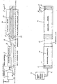
- An embodiment of the invention will now be described by way of example with reference to the accompanying illustrative drawings in which:-
- Figure 1 is a side elevation of a plant for coagulating and drying rubber latex, and
- Figure 2 is a plan view of the plant of Figure 1.
- Referring to the drawings, the material from which the rubber is formed is a fully compounded natural rubber latex containing a chemical dispersion of sulphur, zinc oxide, accelerators, antiozidants, antidegradents and a heat sensitising agent. This latex is prepared in a mixing and metering unit (2) and the prepared latex is fed through a feed pipe (4) and a dispenser (6) onto an endless conveyor belt (8) which is coated with polytetrafluoroethylene (PTFE) to prevent coagulated rubber from sticking to the belt. The feed of the latex onto the belt (8) is controlled to provide a uniform thickness of latex in the range from 1.0mm to 15.0mm across the full width of the conveyor belt (8).
- The belt (8) feeds the latex through a coagulator (10) which produces a combination of microwave energy and a supply of hot air to raise the temperature of the latex to a level to cause the latex to coagulate. The coagulation temperature is normally in the range from 30°C to 90°C depending on the specific formulation of the latex used.
- The coagulator is 12.5 metres in length which includes a 1 metre long latex feed system at the inlet of the coagulator (10). The endless belt (8) extends around a drive pulley and a driven pulley located at the inlet and outlet of the coagulator (10) so that the belt (8) returns through the coagulator (10). The belt is dimensioned to support a latex product width of 1.25 metres and the belt is located up to 1.0 metres from Lhe floor of the coagulator (10). The belt specification and the support structure are designed so that the belt is flat and level over its complete length within plus or minus 0.1mm. The belt drive system is designed to ensure correct and consistent tracking of the belt (8) and provision is made to allow any inclination of the belt from the horizontal to be adjusted on site.
- The invention is not restricted to plant components of any specific size. For example, the width of the apparatus can be varied according to the required width of the product. The length of the coagulator (10) is determined by the required flow rate of the latex; the higher the required latex flow rate, the longer the coagulator (10) has to be.
- A liquid catch tray and a scraper are fitted around the drive pulley to collect and remove uncoagulated latex from the belt. A lightweight roller is fitted at the outlet of the coagulator to assist in removal of uncoagulated latex from the belt. This roller is designed for easy removal to allow access for cleaning the catch tray and scraper. A belt cleaning unit is provided, and this unit is designed so that the belt (8) can be replaced without removing any other part of the apparatus. An illuminated viewing port is fitted to the coagulator so that the coagulation process can be examined.
- A stretch unit (12) consists of an endless conveyor belt (14) coated with PTFE. The belt (14) is dimensioned to accommodate a product width of 1.25 metres. The belt (14) travels around a drive pulley and a driven pulley which are designed to ensure correct and consistent tracking of the belt. The invention is not restricted to plant components for handling a specific product width.
- A pneumatically-operated nip roller is located above the driven return roller of the belt (14).
- In operation, the belt (14) of the stretch unit is driven at a higher speed than the belt (8) of the coagulator (10) so as to increase the speed at which the coagulated rubber leaving the coagulator (10) is conveyed. This speed increase of the coagulated rubber stretches the rubber so as to increase the surface area of the rubber thereby reducing the time the rubber takes to dry.
- The stretched rubber is then conveyed into a drying unit (16) containing three endless conveyor belts (18), (20) and (22) located one above the other. All three belts have an open mesh to improve the drying rate of the rubber, and are coated with PTFE. The three belts are dimensioned to accommodate a product width of 1.25 metres, and the drying unit (16) is designed so that all three belts can be replaced without having to remove any other part of the drying unit.
- The three belts each pass around their associated drive pulley and driven pulley, and the belt drive system is designed to ensure correct and consistent tracking of the belts.
- The coagulated rubber leaving the stretch unit belt (14) passes onto the inlet of the upper drying unit belt (18) which travels in a clockwise direction to deposit rubber from its outlet end onto the inlet end of the intermediate belt (20) which travels in an anti-clockwise direction to deposit the rubber from its own outlet end onto the inlet end ot the lower belt (22) which travels in a clockwise direction. This
lower belt 22 conveys the coagulated rubber to the outlet of the drying unit (16). - The drying unit (16) uses a combination of microwave energy and hot air in the belt triple-pass system to reduce the final moisture content of the coagulated rubber to leas than 1.5%.
- The drying belt (16) in this example of the invention is three pass, i.e. the coagulated rubber is passed in sequence over three belts located in series. The drying unit (16) could however have any odd number of belts in series. The important feature is that the coagulated rubber is retained in the drying unit sufficiently long to dry the rubber to a required level.
- The dispenser (6) is a fully welded construction using stainless steel to ensure that there is no rusting that can lead to contamination of the product.
- To ensure the dispenser is easy to clean all surfaces that come into contact with the latex are coated with polytetrafluoroethylene (PTFE) (Teflon).
- The dispenser (6) is set level across the width of the belt (8) on to which the latex is deposited. This has to be set up very accurately using a built-in levelling system, to ensure that, together with the constant flow delivered via a metering system, the correct thickness of product is achieved.
- The dispenser is moved from the standby position to the ready position using a small compressed air cylinder.
- The design of the dispenser ensures that there are minimum restrictions in the system to provide an even flow to the product. This design, along with the flow and levelness of the system, is essential in giving accurate control to the thickness of the product.
- Microwave chokes are provided at both ends of the above units. These chokes are designed for a maximum product thickness of 150mm but they are adjustable to suit a minimum product thickness of 1.5mm. Microwave leakage detectors are fitted at both ends of each of the above units.
- The recirculating hot air system of the coagulator (10) and the drying unit (16) is designed for automatic control at any temperature from ambient up to a maximum temperature of 100°C, and the warm-up time from ambient to maximum temperature will not exceed 15 minutes.
- Should the system be capable of generating temperatures in excess of the required maximum then interlocks must be provided to prevent this taking place. The control of the recirculating hot air will be carried out by use of a variable speed fan. Distribution of airflow into the units must be such that it does not cause either the leading edge of the product to fall back upon itself or, specifically and of the upmost importance in the coagulator (10), a wave effect on the product surface. All units will be lagged such that the external temperature of any part of the units does not exceed 40°C. All units will be fitted with access doors to facilitate access for cleaning. These doors will be nterlocked to shut down the unit in the event of entering during operation, and to prevent the unit being started up unless all the doors are in position and locked. The interlocks will be wired for no auto-restart. In this embodiment of the invention the metal used will be stainless steel, grade 304L. Product sensors are fitted and linked to the microwave power system to provide automatic power adjustment during the start-up and shutdown, or any other breaks in production.
- The microwave heating process in the coagulator (10) has the following advantages:
- (1) the temperature of the latex can be controlled with great accuracy,
- (2) the coagulation process time is significantly reduced as the microwave energy heats the water containing the rubber from within. In previously known processes the coagulation time could be up to several hours whereas in this process the coagulation time is less than five minutes, and
- (3) this process is energy-efficient when compared to previously known processes.
- The microwave heating process in the drying unit (16) has similar advantages to that of the coagulator (10). The drying time in the drying unit (16) is less than 30 minutes compared to more than 15 hours in a previously known process.
Claims (20)
- A process for the continuous coagulation and drying of rubber latex, the process comprising passing a stream of the latex through a coagulator to form coagulated rubber, introducing the coagulated rubber stream from the coagulator into a dryer downstream of the coagulator, and passing the coagulated rubber through the dryer to dry the rubber, in which the latex stream in the coagulator is heated to cause the latex to coagulate characterised in that the latex stream in the coagulator is heated by a combination of microwave energy and hot air.
- A process as claimed in claim 1 in which the coagulation temperature is in the range from 30°C to 90°C.
- A process as claimed in claim 1 or claim 2 in which the latex stream entering the coagulator has a thickness in the range from 1.0mm to 15.0mm.
- A process as claimed in any preceding claim in which the coagulated rubber in the dryer is heated by a combination of microwave energy and hot air to dry the rubber.
- A process as claimed in claim 4 in which the rubber is dried to a moisture content of less than 1.5%.
- A process as claimed in any preceding claim in which the latex stream speeds, rubber temperatures and microwave energy consumption are computer-controlled.
- A process as claimed in any preceding claim including stretching the coagulated rubber stream as it passes between the coagulator and the dryer.
- A process as claimed in claim 7 in which the coagulated rubber stream is stretched by increasing the speed at which it is conveyed to the dryer.
- An apparatus for the continuous coagulation (10) and drying of rubber latex, the apparatus comprising a coagulator (10), first feeding means to pass a stream of latex through the coagulator (10) to form coagulated rubber, a primary heating means to coagulate the latex stream passing through the coagulator (10), a dryer (16) to receive the coagulated rubber stream from the coagulator (10), second feeding means to pass the coagulated latex stream through the dryer (16), and secondary heating means to dry the coagulated rubber passing through the dryer (16) characterised in that the primary heating means is operable to provide a combination of microwave energy and hot air.
- An apparatus as claimed in claim 9 in which the primary heating means is operable to provide a coagulation temperature in the range from 30°C to 90°C.
- An apparatus as claimed in claim 9 or claim 10 in which the first feeding means is a conveyor belt (8).
- An apparatus as claimed in claim 11 in which the conveyor belt (8) is coated with polytetrafluoroethylene (PTFE).
- An apparatus as claimed in any one of claims 9 to 12 in which the secondary heating means is operable to provide a combination of microwave energy and hot air to dry the rubber.
- An apparatus as claimed in any one of claims 9 to 13 in which the second feeding means is a conveyor belt (18).
- An apparatus as claimed in claim 14 in which the second feeding means is a plurality of conveyor belts (18, 20, 22) arranged so that the coagulated rubber is passed from one belt to the other.
- An apparatus as claimed in claim 14 or claim 15 in which the or each belt (18, 20, 22) is coated with polytetrafluoroethylene (PTFE).
- An apparatus as claimed in any one of claims 9 to 16 including a stretch unit (12) to stretch the coagulated rubber stream leaving the coagulator (10) for the dryer (16).
- An apparatus as claimed in claim 17 in which the stretch unit (12) is operable to increase the speed at which the coagulated rubber stream leaves the coagulator (10) and enters the dryer (16).
- An apparatus as claimed in claim 17 or claim 18 in which the stretch unit (12) comprises a conveyor belt (14) to receive the coagulated rubber leaving the coagulator (10) and to pass the coagulated rubber to the input of the dryer (16).
- An apparatus as claimed in claim 19 in which the belt (14) is coated with polytetrafluoroethylene (PTFE).
Applications Claiming Priority (2)
| Application Number | Priority Date | Filing Date | Title |
|---|---|---|---|
| MY0003975 | 2000-08-29 | ||
| MYPI20003975A MY135746A (en) | 2000-08-29 | 2000-08-29 | A process and apparatus for coagulating and drying latex |
Publications (3)
| Publication Number | Publication Date |
|---|---|
| EP1184148A2 EP1184148A2 (en) | 2002-03-06 |
| EP1184148A3 EP1184148A3 (en) | 2003-08-13 |
| EP1184148B1 true EP1184148B1 (en) | 2006-04-19 |
Family
ID=19749474
Family Applications (1)
| Application Number | Title | Priority Date | Filing Date |
|---|---|---|---|
| EP01115188A Expired - Lifetime EP1184148B1 (en) | 2000-08-29 | 2001-06-22 | A process and apparatus for coagulating and drying latex |
Country Status (5)
| Country | Link |
|---|---|
| US (1) | US6808672B2 (en) |
| EP (1) | EP1184148B1 (en) |
| AT (1) | ATE323574T1 (en) |
| DE (1) | DE60118851D1 (en) |
| MY (1) | MY135746A (en) |
Families Citing this family (7)
| Publication number | Priority date | Publication date | Assignee | Title |
|---|---|---|---|---|
| MY135746A (en) * | 2000-08-29 | 2008-06-30 | Linatex Rubber Products Sdn Bhd | A process and apparatus for coagulating and drying latex |
| CN1330753C (en) * | 2000-08-30 | 2007-08-08 | 北卡罗莱纳州立大学 | Transgenic plants containing molecular inducers that alter protein content |
| KR100569417B1 (en) * | 2004-08-13 | 2006-04-07 | 현대자동차주식회사 | Continuous Surface Modification of Waste Rubber Powder Using Microwave and Surface Modification Method Using the Same |
| WO2007108774A1 (en) * | 2006-03-17 | 2007-09-27 | Sekhar Research Innovations Sdn. Bhd. | An apparatus for use in the rubber drying process |
| DE102008014215A1 (en) * | 2008-03-13 | 2009-09-17 | Krones Ag | Device for heating containers |
| KR102858770B1 (en) * | 2020-10-23 | 2025-09-10 | 주식회사 엘지화학 | Super absorbent polymer drying apparatus |
| CN116834352A (en) * | 2023-06-28 | 2023-10-03 | 常州金橡树橡塑高分子有限公司 | Device and method for producing infinitely long double-color latex tube |
Family Cites Families (15)
| Publication number | Priority date | Publication date | Assignee | Title |
|---|---|---|---|---|
| US2444626A (en) * | 1942-05-09 | 1948-07-06 | Goodrich Co B F | Method and apparatus for continuously transforming a dispersion of a rubbery material into a sheet |
| US3145088A (en) * | 1961-03-03 | 1964-08-18 | Phillips Petroleum Co | Rubber drying |
| US3434220A (en) * | 1967-10-10 | 1969-03-25 | Exxon Research Engineering Co | Microwave drying process for synthetic polymers |
| US3771234A (en) * | 1969-09-09 | 1973-11-13 | Exxon Research Engineering Co | Microwave drying process for synthetic polymers |
| US4055001A (en) * | 1971-11-18 | 1977-10-25 | Exxon Research & Engineering Co. | Microwave drying process for synthetic polymers |
| GB1484342A (en) * | 1974-09-02 | 1977-09-01 | Rubber Res Inst Of Malaysia | Coagulation of rubber latex |
| CA1145896A (en) * | 1979-07-19 | 1983-05-03 | Klaas Tebbens | Coagulation of latex |
| US4391765A (en) * | 1982-06-25 | 1983-07-05 | Dow Corning Corporation | Microwave cured silicone elastomeric foam |
| US4499036A (en) * | 1982-09-20 | 1985-02-12 | W. R. Grace & Co. | Microwave curing of latex-based compositions |
| US4566804A (en) * | 1982-12-16 | 1986-01-28 | Cem Corporation | Apparatuses, processes and articles for controllably heating and drying materials by microwave radiation |
| NL8401784A (en) * | 1984-06-04 | 1986-01-02 | Stahl Chemical Ind | METHOD FOR MANUFACTURING A COAGULE |
| GB2166446B (en) * | 1984-11-02 | 1989-07-05 | Malaysia The Board Of The Rubb | Method and apparatus for the coagulation of natural rubber latex |
| FR2767541B1 (en) * | 1997-08-21 | 1999-10-08 | Hutchinson | SPONGIOUS MATERIAL, MANUFACTURING METHOD THEREOF AND APPLICATIONS THEREOF |
| US6299808B1 (en) * | 2000-06-05 | 2001-10-09 | The Dow Chemical Company | Continuous process for polymerizing, curing and drying high internal phase emulsions |
| MY135746A (en) * | 2000-08-29 | 2008-06-30 | Linatex Rubber Products Sdn Bhd | A process and apparatus for coagulating and drying latex |
-
2000
- 2000-08-29 MY MYPI20003975A patent/MY135746A/en unknown
-
2001
- 2001-06-22 DE DE60118851T patent/DE60118851D1/en not_active Expired - Lifetime
- 2001-06-22 EP EP01115188A patent/EP1184148B1/en not_active Expired - Lifetime
- 2001-06-22 AT AT01115188T patent/ATE323574T1/en not_active IP Right Cessation
- 2001-08-29 US US09/940,494 patent/US6808672B2/en not_active Expired - Lifetime
Also Published As
| Publication number | Publication date |
|---|---|
| MY135746A (en) | 2008-06-30 |
| EP1184148A3 (en) | 2003-08-13 |
| EP1184148A2 (en) | 2002-03-06 |
| US6808672B2 (en) | 2004-10-26 |
| ATE323574T1 (en) | 2006-05-15 |
| DE60118851D1 (en) | 2006-05-24 |
| US20030105181A1 (en) | 2003-06-05 |
Similar Documents
| Publication | Publication Date | Title |
|---|---|---|
| US9939199B2 (en) | Multiple product belt drier for drying pasty and/or powdery materials, particularly for drying sludges from treatment plants or biomass | |
| CN206909658U (en) | The infrared circulation dryer of jujube | |
| US6808672B2 (en) | Process and apparatus for coagulating and drying latex | |
| CN109373739A (en) | A drying system with intelligent control of drying speed | |
| CN106579121A (en) | Method for fast producing dried bamboo shoots | |
| CN213066970U (en) | Device for drying medicinal materials before slicing | |
| EP0409849A1 (en) | Method and device for drying granular material. | |
| CN206463249U (en) | A kind of belt sterilizing and drying cooling system | |
| US20090260255A1 (en) | Drying apparatus for plate elements for electronics and the like, and relative method | |
| CN109405506A (en) | A kind of incrementally hot wind counter-current drying device and method | |
| CN104544531B (en) | Apparatus and method for the puffed tobacco material in the equipment of the tobacco industry | |
| CN108851171A (en) | A kind of blade redrying system and its control method with waste gas circulation function | |
| KR101797431B1 (en) | Multi-Pass Continuous type High-moisture waste and biomass dryer | |
| CN207280146U (en) | A kind of multilayer mesh belt formula ox bed regeneration bedding and padding device | |
| TWI675735B (en) | Solution film forming method | |
| CN115406212B (en) | A device and method for drying grain by microwave heat pump | |
| CN109965334B (en) | A system and method for ensuring the temperature of materials at the entrance of a slice baking machine | |
| WO2004040216A3 (en) | Thermodynamic air treatment machine, method for treating bulk products with treated air using said machine and automatic drier therefor | |
| CN114076516A (en) | A microwave atmospheric pressure automatic drying rubber production line | |
| CN103148689A (en) | Band drying device for preparing polytetrafluoroethylene (PTFE) resin polymerized by dispersion method | |
| CN207079014U (en) | The depolymerization of precipitated calcium carbonate powder, reforming system | |
| CN206377931U (en) | A kind of continuous type heat pump vacuum drier | |
| CN106811807A (en) | Unginned cotton regain regulating system and method before cotton ginning | |
| CN214371595U (en) | A closed-loop intelligent tea dryer | |
| CN204653561U (en) | A kind of curing equipment of potato dough |
Legal Events
| Date | Code | Title | Description |
|---|---|---|---|
| PUAI | Public reference made under article 153(3) epc to a published international application that has entered the european phase |
Free format text: ORIGINAL CODE: 0009012 |
|
| AK | Designated contracting states |
Kind code of ref document: A2 Designated state(s): AT BE CH CY DE DK ES FI FR GB GR IE IT LI LU MC NL PT SE TR |
|
| AX | Request for extension of the european patent |
Free format text: AL;LT;LV;MK;RO;SI |
|
| PUAL | Search report despatched |
Free format text: ORIGINAL CODE: 0009013 |
|
| AK | Designated contracting states |
Designated state(s): AT BE CH CY DE DK ES FI FR GB GR IE IT LI LU MC NL PT SE TR |
|
| AX | Request for extension of the european patent |
Extension state: AL LT LV MK RO SI |
|
| RIC1 | Information provided on ipc code assigned before grant |
Ipc: 7C 08C 1/14 B Ipc: 7C 08C 3/00 B Ipc: 7B 29B 15/04 B Ipc: 7B 29B 13/06 A |
|
| 17P | Request for examination filed |
Effective date: 20040129 |
|
| AKX | Designation fees paid |
Designated state(s): AT BE CH CY DE DK ES FI FR GB GR IE IT LI LU MC NL PT SE TR |
|
| 17Q | First examination report despatched |
Effective date: 20040407 |
|
| GRAP | Despatch of communication of intention to grant a patent |
Free format text: ORIGINAL CODE: EPIDOSNIGR1 |
|
| RTI1 | Title (correction) |
Free format text: A PROCESS AND APPARATUS FOR COAGULATING AND DRYING LATEX |
|
| GRAS | Grant fee paid |
Free format text: ORIGINAL CODE: EPIDOSNIGR3 |
|
| GRAA | (expected) grant |
Free format text: ORIGINAL CODE: 0009210 |
|
| AK | Designated contracting states |
Kind code of ref document: B1 Designated state(s): AT BE CH CY DE DK ES FI FR GB GR IE IT LI LU MC NL PT SE TR |
|
| PG25 | Lapsed in a contracting state [announced via postgrant information from national office to epo] |
Ref country code: IT Free format text: LAPSE BECAUSE OF FAILURE TO SUBMIT A TRANSLATION OF THE DESCRIPTION OR TO PAY THE FEE WITHIN THE PRESCRIBED TIME-LIMIT;WARNING: LAPSES OF ITALIAN PATENTS WITH EFFECTIVE DATE BEFORE 2007 MAY HAVE OCCURRED AT ANY TIME BEFORE 2007. THE CORRECT EFFECTIVE DATE MAY BE DIFFERENT FROM THE ONE RECORDED. Effective date: 20060419 Ref country code: LI Free format text: LAPSE BECAUSE OF FAILURE TO SUBMIT A TRANSLATION OF THE DESCRIPTION OR TO PAY THE FEE WITHIN THE PRESCRIBED TIME-LIMIT Effective date: 20060419 Ref country code: CH Free format text: LAPSE BECAUSE OF FAILURE TO SUBMIT A TRANSLATION OF THE DESCRIPTION OR TO PAY THE FEE WITHIN THE PRESCRIBED TIME-LIMIT Effective date: 20060419 Ref country code: BE Free format text: LAPSE BECAUSE OF FAILURE TO SUBMIT A TRANSLATION OF THE DESCRIPTION OR TO PAY THE FEE WITHIN THE PRESCRIBED TIME-LIMIT Effective date: 20060419 Ref country code: NL Free format text: LAPSE BECAUSE OF FAILURE TO SUBMIT A TRANSLATION OF THE DESCRIPTION OR TO PAY THE FEE WITHIN THE PRESCRIBED TIME-LIMIT Effective date: 20060419 Ref country code: AT Free format text: LAPSE BECAUSE OF FAILURE TO SUBMIT A TRANSLATION OF THE DESCRIPTION OR TO PAY THE FEE WITHIN THE PRESCRIBED TIME-LIMIT Effective date: 20060419 Ref country code: FI Free format text: LAPSE BECAUSE OF FAILURE TO SUBMIT A TRANSLATION OF THE DESCRIPTION OR TO PAY THE FEE WITHIN THE PRESCRIBED TIME-LIMIT Effective date: 20060419 |
|
| REG | Reference to a national code |
Ref country code: GB Ref legal event code: FG4D |
|
| REF | Corresponds to: |
Ref document number: 60118851 Country of ref document: DE Date of ref document: 20060524 Kind code of ref document: P |
|
| REG | Reference to a national code |
Ref country code: IE Ref legal event code: FG4D |
|
| PG25 | Lapsed in a contracting state [announced via postgrant information from national office to epo] |
Ref country code: IE Free format text: LAPSE BECAUSE OF NON-PAYMENT OF DUE FEES Effective date: 20060622 |
|
| PG25 | Lapsed in a contracting state [announced via postgrant information from national office to epo] |
Ref country code: MC Free format text: LAPSE BECAUSE OF NON-PAYMENT OF DUE FEES Effective date: 20060630 |
|
| PG25 | Lapsed in a contracting state [announced via postgrant information from national office to epo] |
Ref country code: GB Free format text: LAPSE BECAUSE OF NON-PAYMENT OF DUE FEES Effective date: 20060719 Ref country code: DK Free format text: LAPSE BECAUSE OF FAILURE TO SUBMIT A TRANSLATION OF THE DESCRIPTION OR TO PAY THE FEE WITHIN THE PRESCRIBED TIME-LIMIT Effective date: 20060719 Ref country code: SE Free format text: LAPSE BECAUSE OF FAILURE TO SUBMIT A TRANSLATION OF THE DESCRIPTION OR TO PAY THE FEE WITHIN THE PRESCRIBED TIME-LIMIT Effective date: 20060719 |
|
| PG25 | Lapsed in a contracting state [announced via postgrant information from national office to epo] |
Ref country code: DE Free format text: LAPSE BECAUSE OF FAILURE TO SUBMIT A TRANSLATION OF THE DESCRIPTION OR TO PAY THE FEE WITHIN THE PRESCRIBED TIME-LIMIT Effective date: 20060720 |
|
| PG25 | Lapsed in a contracting state [announced via postgrant information from national office to epo] |
Ref country code: ES Free format text: LAPSE BECAUSE OF FAILURE TO SUBMIT A TRANSLATION OF THE DESCRIPTION OR TO PAY THE FEE WITHIN THE PRESCRIBED TIME-LIMIT Effective date: 20060730 |
|
| PG25 | Lapsed in a contracting state [announced via postgrant information from national office to epo] |
Ref country code: PT Free format text: LAPSE BECAUSE OF FAILURE TO SUBMIT A TRANSLATION OF THE DESCRIPTION OR TO PAY THE FEE WITHIN THE PRESCRIBED TIME-LIMIT Effective date: 20060919 |
|
| NLV1 | Nl: lapsed or annulled due to failure to fulfill the requirements of art. 29p and 29m of the patents act | ||
| REG | Reference to a national code |
Ref country code: CH Ref legal event code: PL |
|
| PLBE | No opposition filed within time limit |
Free format text: ORIGINAL CODE: 0009261 |
|
| STAA | Information on the status of an ep patent application or granted ep patent |
Free format text: STATUS: NO OPPOSITION FILED WITHIN TIME LIMIT |
|
| 26N | No opposition filed |
Effective date: 20070122 |
|
| GBPC | Gb: european patent ceased through non-payment of renewal fee |
Effective date: 20060719 |
|
| EN | Fr: translation not filed | ||
| PG25 | Lapsed in a contracting state [announced via postgrant information from national office to epo] |
Ref country code: GR Free format text: LAPSE BECAUSE OF FAILURE TO SUBMIT A TRANSLATION OF THE DESCRIPTION OR TO PAY THE FEE WITHIN THE PRESCRIBED TIME-LIMIT Effective date: 20060720 Ref country code: FR Free format text: LAPSE BECAUSE OF FAILURE TO SUBMIT A TRANSLATION OF THE DESCRIPTION OR TO PAY THE FEE WITHIN THE PRESCRIBED TIME-LIMIT Effective date: 20070309 |
|
| PG25 | Lapsed in a contracting state [announced via postgrant information from national office to epo] |
Ref country code: TR Free format text: LAPSE BECAUSE OF FAILURE TO SUBMIT A TRANSLATION OF THE DESCRIPTION OR TO PAY THE FEE WITHIN THE PRESCRIBED TIME-LIMIT Effective date: 20060419 Ref country code: LU Free format text: LAPSE BECAUSE OF NON-PAYMENT OF DUE FEES Effective date: 20060622 |
|
| PG25 | Lapsed in a contracting state [announced via postgrant information from national office to epo] |
Ref country code: FR Free format text: LAPSE BECAUSE OF FAILURE TO SUBMIT A TRANSLATION OF THE DESCRIPTION OR TO PAY THE FEE WITHIN THE PRESCRIBED TIME-LIMIT Effective date: 20060419 Ref country code: CY Free format text: LAPSE BECAUSE OF FAILURE TO SUBMIT A TRANSLATION OF THE DESCRIPTION OR TO PAY THE FEE WITHIN THE PRESCRIBED TIME-LIMIT Effective date: 20060419 |