EP1184088A2 - Coating method and apparatus - Google Patents
Coating method and apparatus Download PDFInfo
- Publication number
- EP1184088A2 EP1184088A2 EP01307181A EP01307181A EP1184088A2 EP 1184088 A2 EP1184088 A2 EP 1184088A2 EP 01307181 A EP01307181 A EP 01307181A EP 01307181 A EP01307181 A EP 01307181A EP 1184088 A2 EP1184088 A2 EP 1184088A2
- Authority
- EP
- European Patent Office
- Prior art keywords
- substrate
- applicator
- wiper
- arms
- arm
- Prior art date
- Legal status (The legal status is an assumption and is not a legal conclusion. Google has not performed a legal analysis and makes no representation as to the accuracy of the status listed.)
- Granted
Links
- 238000000576 coating method Methods 0.000 title claims abstract description 82
- 239000011248 coating agent Substances 0.000 claims abstract description 75
- 238000000034 method Methods 0.000 claims abstract description 21
- 239000000758 substrate Substances 0.000 claims description 47
- 238000012546 transfer Methods 0.000 claims description 20
- 239000000463 material Substances 0.000 description 11
- 238000004519 manufacturing process Methods 0.000 description 7
- 238000005507 spraying Methods 0.000 description 5
- 238000011161 development Methods 0.000 description 4
- 238000007639 printing Methods 0.000 description 4
- 229920001971 elastomer Polymers 0.000 description 3
- 239000000126 substance Substances 0.000 description 3
- 238000007598 dipping method Methods 0.000 description 2
- 229920001973 fluoroelastomer Polymers 0.000 description 2
- 238000010586 diagram Methods 0.000 description 1
- 230000000694 effects Effects 0.000 description 1
- 230000007613 environmental effect Effects 0.000 description 1
- 239000005002 finish coating Substances 0.000 description 1
- 238000007429 general method Methods 0.000 description 1
- 230000005484 gravity Effects 0.000 description 1
- 238000010438 heat treatment Methods 0.000 description 1
- 230000006698 induction Effects 0.000 description 1
- 238000003780 insertion Methods 0.000 description 1
- 230000037431 insertion Effects 0.000 description 1
- 239000010410 layer Substances 0.000 description 1
- 239000002184 metal Substances 0.000 description 1
- 108091008695 photoreceptors Proteins 0.000 description 1
- 239000002861 polymer material Substances 0.000 description 1
- 238000004886 process control Methods 0.000 description 1
- 238000012545 processing Methods 0.000 description 1
- 230000005855 radiation Effects 0.000 description 1
- 239000012858 resilient material Substances 0.000 description 1
- 238000005096 rolling process Methods 0.000 description 1
- 239000007921 spray Substances 0.000 description 1
- 239000002344 surface layer Substances 0.000 description 1
- 238000013519 translation Methods 0.000 description 1
- 238000009827 uniform distribution Methods 0.000 description 1
Images


Classifications
-
- B—PERFORMING OPERATIONS; TRANSPORTING
- B05—SPRAYING OR ATOMISING IN GENERAL; APPLYING FLUENT MATERIALS TO SURFACES, IN GENERAL
- B05C—APPARATUS FOR APPLYING FLUENT MATERIALS TO SURFACES, IN GENERAL
- B05C11/00—Component parts, details or accessories not specifically provided for in groups B05C1/00 - B05C9/00
- B05C11/02—Apparatus for spreading or distributing liquids or other fluent materials already applied to a surface ; Controlling means therefor; Control of the thickness of a coating by spreading or distributing liquids or other fluent materials already applied to the coated surface
- B05C11/04—Apparatus for spreading or distributing liquids or other fluent materials already applied to a surface ; Controlling means therefor; Control of the thickness of a coating by spreading or distributing liquids or other fluent materials already applied to the coated surface with blades
-
- B—PERFORMING OPERATIONS; TRANSPORTING
- B05—SPRAYING OR ATOMISING IN GENERAL; APPLYING FLUENT MATERIALS TO SURFACES, IN GENERAL
- B05C—APPARATUS FOR APPLYING FLUENT MATERIALS TO SURFACES, IN GENERAL
- B05C5/00—Apparatus in which liquid or other fluent material is projected, poured or allowed to flow on to the surface of the work
- B05C5/002—Apparatus in which liquid or other fluent material is projected, poured or allowed to flow on to the surface of the work the work consisting of separate articles
Definitions
- Fusing rolls which are used to fix the toner image on a substrate, represent a component that is typically in the form of polymeric rolls or belts.
- bias charge rolls BCRS
- bias transfer rolls BTRS
- Such rolls and belts include the pressure or backup roll used with a fusing roll to fix the toner image on a substrate, donor rolls which transfer oil to the fuser roll that assists in releasing the toner from the fuser roll, intermediate transfer rolls and belts that transfer developed images, photoconductive belts and rolls, and those belts and rolls used in Hybrid Scavangeless Development (HSD). All of these a polymeric rolls and belts are typically manufactured by spraying or by dipping of the above mentioned components.
- the fusing of the toner image to the paper to form a permanent record of the image is an important part of the xerographic process. Fusing of the toner image is typically done by heat fixation.
- the heat fixation may be in the form of radiation, conduction, convection or induction.
- Most modern xerographic processes utilize conduction heating of the toner image to adhere the image to the paper.
- a fusing roll is placed in rolling contact with a backup roll forming a nip.
- the paper having the transferred toner image is fed between the rolls through the nip. Heat from the fusing roll together with the pressure within the nip, between the fuser roll and the backup roll, serve to fuse the image to the paper. Heat is typically applied internally within the roll and is transferred through the substrate of the roll onto the periphery of the roll and onto the paper.
- the rolls typically include a thermally conductive substrate with a surface layer which is also thermally conductive.
- the fuser roll coating is conformable to the paper.
- the coating may be in the form of a rubber or polymer material, e.g. a fluoroelastomer coating. Applying fluorelastomer and other rubber type coatings to fuser roll substrates are fraught with many problems.
- the coating may be applied to the substrate by two typical methods which are dipping of the substrate into a bath of coating solution or spraying the surface of the substrate with the coating material.
- Spraying is the typical method for the manufacture of fluoroelastomer rollers and it is slow and costly. Also, the spraying process requires having the coating solution in a form that is volatile including many volatile organic chemicals. Further, the spraying process is prone to air pockets or pits forming in the coating. These pits or air pockets in the coating material of the roll result in improper fusing and poor image quality. Because of the nature of the spray process, much of the coating material is lost in the atmosphere requiring an excess amount of the expensive coating material utilized. Also, the loss of the volatile chemicals result in expensive containment costs for systems to contain the volatile chemicals as well as disposal costs of these materials.
- This invention is intended to alleviate at least some of the above-mentioned problems for at least some of the several components in the electrophotographic printing process described above which are in the form of polymeric rolls and belts.
- a more recent process attempts to apply coating solution by dripping material over a horizontally rotating cylinder. With this process a portion of the material adheres to the cylinder and the remainder drips from the cylinder.
- the amount of material added to the roll is not precisely controlled as the percentage that adheres varies as parameters change over the production run. Also the material forms a wavy coating surface where the material is poured.
- This so called flow coating method may be enhanced by means of a flexible wiper applied to the surface of the roll as the coating is applied, as described in US-A-5,871,832. This tends to provide a more even coating thickness.
- a flow coating process is adapted to apply a coating to the end surfaces of a cylindrical fuser roll.
- a coating station is designed for insertion within the coating operation of a fuser production line.
- the coating station comprises a nozzle mounted in the path of the production line for applying a flouroelastomer (polymeric) coating solution to a cylindrical fuser roll.
- the fuser roll is secured on a transport for movement through the coating station in a direction transverse to the axis of the roll.
- the fuser roll is mounted on the transport for rotary movement about its longitudinal axis.
- the process control stops the fuser roll in the station and rotates the roll under the nozzle while the nozzle translates over the roll in a motion which is parallel to the axis of the roll.
- To coat the ends of the roll the nozzle is held stationery at the ends of the roll, while the roll is rotated.
- a pair of arms are mounted on a transfer head in the station for movement parallel to and coordinated with the nozzle.
- Each of the arms are constructed to independently rotate towards and away from the fuser roll between a retracted position and an operational position. Rotation of the arms is controlled so that only one nozzle is operational at a given time.
- the arm assembly In the operational position, the arm assembly is located at the end of the fuser roll and one of the arms extends generally horizontal under the nozzle.
- the nozzle When the nozzle begins its application cycle, it will generally be positioned above one end of the fuser roll. According to this invention, the arm assembly is positioned at the same axial location as the nozzle either just ahead or just behind the roll. In the operative position the stream of solution from the nozzle will flow vertically downward immediately adjacent to the end of the roll. The operative arm is rotated under the stream to cause a deflection of the stream towards the end of the roll.
- Each of the arms are formed having a near edge and a far edge relative to the end of the fuser roll.
- the near edge is constructed having a surface which is shaped to deflect the coating stream towards the end surface of the roller.
- the far edge is shaped to direct excess coating solution away from the roller to avoid splattering the cylindrical surface and marring the finish coating of the cylinder.
- apparatus 100 is shown for coating polymeric printing rolls or belts for example: xerographic fuser roll 48. It should be appreciated that the apparatus 100 may be utilized for flow coating any of a number of polymeric printing rolls or belts including but not limited to bias charge rolls (BCRs), bias transfer rolls (BTRs), pressure rolls, backup rolls, fuser donor rolls, intermediate transfer rolls and belts, photoconductive belts and rolls, development rolls and belts and development donor rolls and belts, and Hybrid Scavangeless Development rolls and belts.
- BCRs bias charge rolls
- BTRs bias transfer rolls
- pressure rolls backup rolls
- fuser donor rolls intermediate transfer rolls and belts
- photoconductive belts and rolls development rolls and belts and development donor rolls and belts
- Hybrid Scavangeless Development rolls and belts Hybrid Scavangeless Development rolls and belts.
- the apparatus 100 may be used to apply coating solution 102 to surface 104 of the fuser roll 48.
- the coating solution is pumped via pump 106 through a conduit typically in the form of a pipe 110 to an applicator 112 including nozzle 114 through which the coating solution 102 flows onto cylindrical surface 104 of the roll 48.
- the coating solution 102 is applied to the surface 104 in a spiral fashion by rotating fuser roll 48 about its longitudinal axis 116, while the applicator 112 translates in a direction parallel to the longitudinal axis 116. This process is referred to as flow coating.
- the apparatus 100 may have any suitable form and may consist of any equipment capable of rotating the fuser roll 48 about longitudinal axis 116 while translating the applicator 112 in a direction parallel to the longitudinal axis 116. Specialty equipment may be designed which will rotate the fuser roll while translating the applicator within a controlled space, thereby permitting the proper enclosure of the apparatus 100 to contain the volatile coating solution and to maintain the environmental conditions necessary for quality coatings from this process.
- a member in the form of a loop type guide or wiper 103 against the surface 104 of the roll 48 as the coating solution 102 is applied to the roll significantly improves the uniformity of the coating as it is applied to the surface 104 of roll 48.
- the longitudinal axis 116 of the roll 48 is positioned horizontally with respect to the floor of the building in which the apparatus is housed to allow the affects of gravity to properly distribute the coating solution 102 about the surface 104.
- wiper 103 is shown extending towards roll 48 from the support block 2 and will engage surface 104 during the coating operation.
- the tip 105 of the wiper 103 is formed as a loop of thin flexible material which deforms slightly to conform to the contour of the roll 48.
- the coating solution 102 is applied in alignment with the wiper 103.
- the applicator 112 is preferably positioned above the fuser roll 48 so that the stream of coating solution coming from the nozzle 114 may flow over the surface 104 of the roll 48.
- Tip 118 of nozzle 114 is preferably spaced a distance H above the surface 104 of the roll 48. If the tip 118 is placed too far from the surface 104 the coating solution 102 congeal before it reaches the surface 104. If the tip 118 is placed too closely to the surface 104, it will touch with an undesirable effect.
- a distance H of approximately 1/4 of an inch (6mm) is acceptable to position the applicator 112 at a position F of approximately one inch (25mm) from vertical axis 122 of the roll in the direction of rotation 124 of the roll.
- the dynamics of the rotation of the roll and its position on the surface of the roll assist in the uniform distribution of the solution 102 on the roll.
- the flow coating process described above is further adapted to apply the polymeric coating to the ends of a fuser roll.
- the process and apparatus of this invention is not limited to fuser rolls, but includes the manufacturing of all similar rolls.
- an end coating module 1 is mounted on a transfer frame 11 through a support block 2.
- Support block 2 is mounted for movement along guide rail 3 in a direction parallel to the roll 48.
- a pair of arms 4 and 5 are mounted on drive blocks 9 and 10 for rotary movement about the guide rail 3 towards and away from the roller 48.
- Support block 2 is shown in figure 1 to be part of the transfer frame 11. Accordingly the end coating module 1 will move axially as a unit with the coating solution applicator 112.
- end roll 48 is depicted having a forward end 12 and a rear end 13. As shown in figure 2, each of the ends has a resilient edge 7, a metallic end plate 6, and a bearing journal 14.
- the bearing journal 14 is constructed to receive a mounting shaft for final assembly.
- the roll 48 is mounted on its shaft for rotation in the clockwise direction, as shown by arrow 124. This rotary motion coupled with the translation of the applicator 112 will apply the coating to the cylindrical surface 104 of the roll 48 with a pitch.
- the end coating module 1 allows the flow coating method to be used for applying polymeric coating to the end plates 6 and edge 7 of the roller 48 to seal the edge and protect the underlying substrate.
- the applicator must be controlled to direct the flow of coating solution to the edge of the wiper arms 4 and 5. Coordination of the position of the support block 2 and the applicator 112 is needed.
- the applicator is mounted on the transfer frame for movement relative to the support block 2 between multiple positions, one at which the coating solution is applied to the edge of the forward arm 5 and the other position at which the solution 102 is applied to the rear arm 4. In the event that full coating of the surface 104 is also to be accomplished at the same station, the nozzle 118 must be aligned with the wiper 103.
- arm 4 it is preferred to use a pair of arms for reasons that will be described later in this application.
- the forward and rear wiper arms 4 and 5 are fixed to drive blocks 9 and 10.
- the drive blocks may be associated with any appropriate drive mechanism such as motor driven gears or belts to provide a suitably controllable rotary motion to arms 4 and 5.
- the arms 4 and 5 may be mounted independently of the guide rail 3.
- the arms 4 and 5 rotate between two positions an operational position and a retracted position, as shown in figures 1 and 2. Only one of the arms will be rotated to its operational position at the same time depending on whether the forward end 12 or rear end 13 is being coated. Both of the arms will be in the retracted position when the assembly is moved from one end to the other.
- Arms 4 and 5 are shaped, as shown in figures 2b and 2c, and are constructed generally with a flexible edge 15 fixed to a stub 17.
- Stub 17 extends at an angle to the body 16 of the arms 4 and 5 to facilitate the wiping action of the edge 15.
- the extended body portion 16 is designed to direct excess amounts of coating solution 102 away from the roll 48 to prevent splattering and resulting marring of the finish of the cylindrical surface of roll 48.
- the arms 4 and 5 are constructed with opposing profiles to properly engage and cooperate in the desired manner with the applicator 112.
- arms 4 and 5 could be constructed as shown in figure 5.
- a rigid arm 20 extends outward from the drive block 21 and a flexible end blade 22 is connected at the end 23 of arm 20.
- the wiping action is provided by forward edge 24 or rear edge 25, depending on which end of the roll is being processed. In the event that two end wiper arms are provided as described above then only one of the edges of the blade 22 will be operational.
- a microprocessor 18 or other computer component is provided.
- Microprocessor 18 is connected to receive data from sensors 19 and 20.
- Sensor 19 monitors the position of the arms 4 and 5 on support block 2, while sensor 20 monitors the axial position of the applicator 112.
- Sensor data is processed by microprocessor 18 and signals are generated to appropriately align the components and adjust the arms to their appropriate positions.
- the process starts at the rear end 13 and when the components are sensed to be in this position, wiper arm 4 is rotated into position engaging edge 15 against the end 13 of the roll 48.
- the applicator is aligned with wiper arm 4 and coating solution 102 is dispensed.
- the solution 102 flows over edge 15 to coat the end surface 13 with excess being directed away by the body portion 16 of arm 4.
- This invention may also be effective in coating rolls which have highly angular profiles or tapers.
Landscapes
- Coating Apparatus (AREA)
- Application Of Or Painting With Fluid Materials (AREA)
Abstract
Description
- Several components in the electrophotographic printing process are in the form of polymeric rolls and belts. Fusing rolls, which are used to fix the toner image on a substrate, represent a component that is typically in the form of polymeric rolls or belts. Also included among these components are bias charge rolls (BCRS) and bias transfer rolls (BTRS) which electrostatically charge the photoreceptor. In addition such rolls and belts include the pressure or backup roll used with a fusing roll to fix the toner image on a substrate, donor rolls which transfer oil to the fuser roll that assists in releasing the toner from the fuser roll, intermediate transfer rolls and belts that transfer developed images, photoconductive belts and rolls, and those belts and rolls used in Hybrid Scavangeless Development (HSD). All of these a polymeric rolls and belts are typically manufactured by spraying or by dipping of the above mentioned components.
- It is particularly difficult to manufacture fuser rolls and belts because of the elevated temperatures and pressures to which these rolls are subjected and the accurate size and finish requirements necessary to ensure proper copy quality.
- The fusing of the toner image to the paper to form a permanent record of the image is an important part of the xerographic process. Fusing of the toner image is typically done by heat fixation. The heat fixation may be in the form of radiation, conduction, convection or induction. Most modern xerographic processes utilize conduction heating of the toner image to adhere the image to the paper. To accomplish this purpose a fusing roll is placed in rolling contact with a backup roll forming a nip. The paper having the transferred toner image is fed between the rolls through the nip. Heat from the fusing roll together with the pressure within the nip, between the fuser roll and the backup roll, serve to fuse the image to the paper. Heat is typically applied internally within the roll and is transferred through the substrate of the roll onto the periphery of the roll and onto the paper.
- The rolls typically include a thermally conductive substrate with a surface layer which is also thermally conductive. To assure uniform transfer of the image onto the paper, typically the fuser roll coating is conformable to the paper. For example, the coating may be in the form of a rubber or polymer material, e.g. a fluoroelastomer coating. Applying fluorelastomer and other rubber type coatings to fuser roll substrates are fraught with many problems. The coating may be applied to the substrate by two typical methods which are dipping of the substrate into a bath of coating solution or spraying the surface of the substrate with the coating material.
- Spraying is the typical method for the manufacture of fluoroelastomer rollers and it is slow and costly. Also, the spraying process requires having the coating solution in a form that is volatile including many volatile organic chemicals. Further, the spraying process is prone to air pockets or pits forming in the coating. These pits or air pockets in the coating material of the roll result in improper fusing and poor image quality. Because of the nature of the spray process, much of the coating material is lost in the atmosphere requiring an excess amount of the expensive coating material utilized. Also, the loss of the volatile chemicals result in expensive containment costs for systems to contain the volatile chemicals as well as disposal costs of these materials.
- This invention is intended to alleviate at least some of the above-mentioned problems for at least some of the several components in the electrophotographic printing process described above which are in the form of polymeric rolls and belts.
- A more recent process attempts to apply coating solution by dripping material over a horizontally rotating cylinder. With this process a portion of the material adheres to the cylinder and the remainder drips from the cylinder. The amount of material added to the roll is not precisely controlled as the percentage that adheres varies as parameters change over the production run. Also the material forms a wavy coating surface where the material is poured. This so called flow coating method may be enhanced by means of a flexible wiper applied to the surface of the roll as the coating is applied, as described in US-A-5,871,832. This tends to provide a more even coating thickness.
- During the processing in accordance with the prior art there is little attention paid to the end surfaces of the rolls. It is generally desirable to coat the ends of the roll to close the edges of the coating and seal the metal end plates. It is a purpose of this invention to provide an apparatus and method for coating the ends of a fuser roll in conjunction with the coating of the cylindrical surface of such rolls.
- A flow coating process is adapted to apply a coating to the end surfaces of a cylindrical fuser roll. To accomplish this purpose a coating station is designed for insertion within the coating operation of a fuser production line. The coating station comprises a nozzle mounted in the path of the production line for applying a flouroelastomer (polymeric) coating solution to a cylindrical fuser roll. The fuser roll is secured on a transport for movement through the coating station in a direction transverse to the axis of the roll. The fuser roll is mounted on the transport for rotary movement about its longitudinal axis. The process control stops the fuser roll in the station and rotates the roll under the nozzle while the nozzle translates over the roll in a motion which is parallel to the axis of the roll. To coat the ends of the roll, the nozzle is held stationery at the ends of the roll, while the roll is rotated.
- A pair of arms are mounted on a transfer head in the station for movement parallel to and coordinated with the nozzle. Each of the arms are constructed to independently rotate towards and away from the fuser roll between a retracted position and an operational position. Rotation of the arms is controlled so that only one nozzle is operational at a given time. In the operational position, the arm assembly is located at the end of the fuser roll and one of the arms extends generally horizontal under the nozzle.
- When the nozzle begins its application cycle, it will generally be positioned above one end of the fuser roll. According to this invention, the arm assembly is positioned at the same axial location as the nozzle either just ahead or just behind the roll. In the operative position the stream of solution from the nozzle will flow vertically downward immediately adjacent to the end of the roll. The operative arm is rotated under the stream to cause a deflection of the stream towards the end of the roll.
- Each of the arms are formed having a near edge and a far edge relative to the end of the fuser roll. The near edge is constructed having a surface which is shaped to deflect the coating stream towards the end surface of the roller. The far edge is shaped to direct excess coating solution away from the roller to avoid splattering the cylindrical surface and marring the finish coating of the cylinder.
- A particular embodiment in accordance with this invention will now be described with reference to the accompanying drawings; in which:-
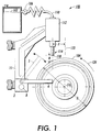
- Figure 1 is schematic illustration of the roll coating apparatus of this invention;
- Figure 2a is schematic illustration of the end coating apparatus of this invention;
- Figure 2b is an illustration showing the engagement of the wiper arms with the ends of the roll;
- Figure 2c is an end view showing the profile of the wiper arms;
- Figure 3 is a chart of the process of this invention; and,
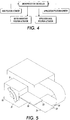
- Figure 4 is a block diagram of the control system for the apparatus of this invention.
-
- Referring now to Figure 1,
apparatus 100 is shown for coating polymeric printing rolls or belts for example:xerographic fuser roll 48. It should be appreciated that theapparatus 100 may be utilized for flow coating any of a number of polymeric printing rolls or belts including but not limited to bias charge rolls (BCRs), bias transfer rolls (BTRs), pressure rolls, backup rolls, fuser donor rolls, intermediate transfer rolls and belts, photoconductive belts and rolls, development rolls and belts and development donor rolls and belts, and Hybrid Scavangeless Development rolls and belts. - The
apparatus 100 may be used to applycoating solution 102 tosurface 104 of thefuser roll 48. The coating solution is pumped viapump 106 through a conduit typically in the form of apipe 110 to anapplicator 112 includingnozzle 114 through which thecoating solution 102 flows ontocylindrical surface 104 of theroll 48. - The
coating solution 102 is applied to thesurface 104 in a spiral fashion by rotatingfuser roll 48 about itslongitudinal axis 116, while theapplicator 112 translates in a direction parallel to thelongitudinal axis 116. This process is referred to as flow coating. - The
apparatus 100 may have any suitable form and may consist of any equipment capable of rotating thefuser roll 48 aboutlongitudinal axis 116 while translating theapplicator 112 in a direction parallel to thelongitudinal axis 116. Specialty equipment may be designed which will rotate the fuser roll while translating the applicator within a controlled space, thereby permitting the proper enclosure of theapparatus 100 to contain the volatile coating solution and to maintain the environmental conditions necessary for quality coatings from this process. - According to the present invention, applicants have found that the placement of a member in the form of a loop type guide or
wiper 103 against thesurface 104 of theroll 48 as thecoating solution 102 is applied to the roll, significantly improves the uniformity of the coating as it is applied to thesurface 104 ofroll 48. In some instances, thelongitudinal axis 116 of theroll 48 is positioned horizontally with respect to the floor of the building in which the apparatus is housed to allow the affects of gravity to properly distribute thecoating solution 102 about thesurface 104. - In figure 2a,
wiper 103 is shown extending towardsroll 48 from thesupport block 2 and will engagesurface 104 during the coating operation. Thetip 105 of thewiper 103 is formed as a loop of thin flexible material which deforms slightly to conform to the contour of theroll 48. During the coating of thecylindrical portion 104 of theroll 48, thecoating solution 102 is applied in alignment with thewiper 103. - The
applicator 112 is preferably positioned above thefuser roll 48 so that the stream of coating solution coming from thenozzle 114 may flow over thesurface 104 of theroll 48.Tip 118 ofnozzle 114 is preferably spaced a distance H above thesurface 104 of theroll 48. If thetip 118 is placed too far from thesurface 104 thecoating solution 102 congeal before it reaches thesurface 104. If thetip 118 is placed too closely to thesurface 104, it will touch with an undesirable effect. For a roll having a diameter D of approximately four inches (100mm), the applicants have found that a distance H of approximately 1/4 of an inch (6mm) is acceptable to position theapplicator 112 at a position F of approximately one inch (25mm) fromvertical axis 122 of the roll in the direction ofrotation 124 of the roll. The dynamics of the rotation of the roll and its position on the surface of the roll assist in the uniform distribution of thesolution 102 on the roll. - In accordance with this invention, the flow coating process described above is further adapted to apply the polymeric coating to the ends of a fuser roll. As stated above the process and apparatus of this invention is not limited to fuser rolls, but includes the manufacturing of all similar rolls. As shown in figures 1 and 2, an
end coating module 1 is mounted on atransfer frame 11 through asupport block 2.Support block 2 is mounted for movement along guide rail 3 in a direction parallel to theroll 48. - A pair of
arms drive blocks roller 48.Support block 2 is shown in figure 1 to be part of thetransfer frame 11. Accordingly theend coating module 1 will move axially as a unit with thecoating solution applicator 112. These components of the system need not necessarily be one unit as long as their axial movement relative to theroll 48 is coordinated. - For the purpose of this description,
end roll 48 is depicted having aforward end 12 and arear end 13. As shown in figure 2, each of the ends has a resilient edge 7, ametallic end plate 6, and abearing journal 14. In general the type of rolls processed by this apparatus have a soft outer layer constructed of rubber or other similar resilient material, however a rigid substrate may also be coated by using this invention. The bearingjournal 14 is constructed to receive a mounting shaft for final assembly. In the production line of this process, theroll 48 is mounted on its shaft for rotation in the clockwise direction, as shown byarrow 124. This rotary motion coupled with the translation of theapplicator 112 will apply the coating to thecylindrical surface 104 of theroll 48 with a pitch. - The
end coating module 1 allows the flow coating method to be used for applying polymeric coating to theend plates 6 and edge 7 of theroller 48 to seal the edge and protect the underlying substrate. To accomplish this the applicator must be controlled to direct the flow of coating solution to the edge of thewiper arms support block 2 and theapplicator 112 is needed. The applicator is mounted on the transfer frame for movement relative to thesupport block 2 between multiple positions, one at which the coating solution is applied to the edge of theforward arm 5 and the other position at which thesolution 102 is applied to therear arm 4. In the event that full coating of thesurface 104 is also to be accomplished at the same station, thenozzle 118 must be aligned with thewiper 103. Although it may be advantageous in some circumstances to use only a single wiper arm, for example:arm 4, it is preferred to use a pair of arms for reasons that will be described later in this application. - The forward and
rear wiper arms blocks arms arms arms forward end 12 orrear end 13 is being coated. Both of the arms will be in the retracted position when the assembly is moved from one end to the other. -
Arms stub 17.Stub 17 extends at an angle to thebody 16 of thearms extended body portion 16 is designed to direct excess amounts ofcoating solution 102 away from theroll 48 to prevent splattering and resulting marring of the finish of the cylindrical surface ofroll 48. Thearms applicator 112. - In the alternative, the shape of
arms rigid arm 20 extends outward from thedrive block 21 and aflexible end blade 22 is connected at theend 23 ofarm 20. The wiping action is provided byforward edge 24 orrear edge 25, depending on which end of the roll is being processed. In the event that two end wiper arms are provided as described above then only one of the edges of theblade 22 will be operational. - In order to control the operation of the components of the system of this invention, a microprocessor 18 or other computer component is provided. Microprocessor 18 is connected to receive data from
sensors 19 and 20. Sensor 19 monitors the position of thearms support block 2, whilesensor 20 monitors the axial position of theapplicator 112. Sensor data is processed by microprocessor 18 and signals are generated to appropriately align the components and adjust the arms to their appropriate positions. In the chart of figure 4, the process starts at therear end 13 and when the components are sensed to be in this position,wiper arm 4 is rotated into position engaging edge 15 against theend 13 of theroll 48. The applicator is aligned withwiper arm 4 andcoating solution 102 is dispensed. Thesolution 102 flows over edge 15 to coat theend surface 13 with excess being directed away by thebody portion 16 ofarm 4. - It should be noted that while the
solution 102 is being applied to theend surface 13, the roll is rotating, but the wiper arm assembly is axially stationary. After a predetermined length of time has expired, the controller 18 will actuate movement of theapplicator 112 to theforward end 12 for coating the other end of the roll. During such movement, thewiper arms movement coating solution 102 may be applied to the cylindrical surface ofroll 48. It may be preferable to coat this surface at a different station. To continue coatingsurface 104,Arm 4 is raised to avoid contact with theroll 48 and theapplicator 112 is aligned with thewiper 103.Roll 48 turns as the coating components traverse the length of theroll 48. At theforward end 12,arm 5 is lowered and theapplicator 112 is aligned witharm 5 to coat thefar end 12. - In this manner the general method of flowing coating is used effectively apply polymeric coating to the sides a cylindrical roll. This invention may also be effective in coating rolls which have highly angular profiles or tapers.
Claims (8)
- A wiper assembly (1) for use in the application of a polymeric coating to the ends of a substrate (48), in which the substrate (48) is positioned to receive a stream of coating solution from an applicator (118) mounted generally above the substrate (48), said substrate (48) being mounted to rotate under said applicator (118) about a first axis, said wiper assembly (1) comprising:wherein said applicator (118) applies coating solution to the wiper arm (4,5) when said arm (4,5) is rotated into engagement with said first or second end of said substrate (48) and said coating solution is allowed to flow onto the end of the substrate (48) as it is rotated.a transfer block (2) mounted for movement relative to the substrate (48) in a direction parallel to said first axis of rotation of the substrate (48) from a first end of said substrate to a second end of said substrate (48) ;at least one wiper arm (4,5) mounted on the transfer block (2) for rotation about a second axis parallel to said first axis, said second axis being displaced from said first axis a predetermined distance, and said wiper arm (4,5) having a length sufficient to bridge said predetermined distance and engage said first or second ends of said substrate (48) ;a rotary drive (10) operatively associated with said wiper arm (4,5) to cause rotary movement of said wiper arm (4,5) between a position of engagement with said first or second ends and a position displaced from said substrate (48);a linear drive operatively associated with said transfer block (2) to cause said transfer block (2) to move parallel to said first axis in coordination with said applicator (118); and,
- A wiper assembly according to claim 1, further comprising a controller operatively connected to said drives and the applicator (118) to align said applicator with said wiper arm (4,5) and apply coating solution to said wiper arm (4,5) when said wiper arm is adjacent to said end of said substrate (48).
- A wiper assembly according to claim 1 or 2,
wherein said at least one arm comprises a pair of arms (4,5) mounted on said transfer block (2) for rotary motion in parallel planes, wherein one of said arms (4) is positioned to engage said first end (6) of said substrate (48) and the other of said arms (5) is positioned to engage said second end (12) of said substrate (148), and wherein said applicator (118) is coordinated with one or the other of said pair of wiper arms depending on the location of the applicator (118) and transfer block (2). - A wiper assembly according to claim 3, wherein said applicator (118) is mounted for movement relative to said transfer block (2) to allow said applicator (118) to be aligned with either of said wiper arms (4,5) of said pair.
- A wiper assembly according to any one of the preceding claims, wherein said wiper arm (4,5) is constructed having a rigid portion and a flexible portion, said flexible portion connected to the rigid portion for engagement with the substrate.
- A wiper assembly according to any one of the preceding claims, further comprising a flexible wiper blade (105) mounted on said transfer block (2) for movement therewith, said blade (105) extending towards the substrate (48) to engage the substrate (48) and wherein said applicator (118) applies coating solution to the substrate (48) in alignment with said blade (105), to allow said blade (105) to wipe said solution over said substrate (48) as it rotates and said applicator (118) and transfer block (2) are moved parallel to said first axis.
- In a system for use in the application of a polymeric coating a substrate, in which the substrate is positioned to receive a stream of coating solution from an applicator mounted generally above the substrate, said substrate being mounted to rotate under said applicator about a first axis, a method of applying said coating to the ends of said substrate comprising the steps of:constructing a wiper assembly having at least one arm for engagement with said ends of the substrate;providing coordinated movement of said applicator and said wiper assembly relative to said substrate in a direction parallel to the said first axis;moving said applicator to an end of said substrate and engaging said wiper arm with said end of said substrate;applying said coating solution to the wiper arm and allowing said solution to flow to the end of said substrate as the substrate is rotated;when said end is coated withdrawing said wiper arm to a position at which there is a clearance between said wiper arm and said substrate; andmoving said applicator and wiper assembly in coordination to said other end of said substrate.
- A method according to claim 7, wherein said step of constructing said wiper assembly having at least one arm further includes constructing a pair of first and second arms mounted for rotary motion in parallel planes, wherein one of said arms is positioned to engage said first end of said substrate and the other of said arms is positioned to engage said second end of said substrate, and further comprising the steps of:moving said arms into a retracted position to allow movement of the wiper assembly from one end of said substrate to the other end;engaging one of said first and second arms with its respective end of said substrate; andaligning said applicator with said engaged arms.
Applications Claiming Priority (2)
| Application Number | Priority Date | Filing Date | Title |
|---|---|---|---|
| US09/655,078 US6540830B1 (en) | 2000-09-05 | 2000-09-05 | Apparatus for coating the ends of fuser rolls |
| US655078 | 2000-09-05 |
Publications (3)
| Publication Number | Publication Date |
|---|---|
| EP1184088A2 true EP1184088A2 (en) | 2002-03-06 |
| EP1184088A3 EP1184088A3 (en) | 2002-11-20 |
| EP1184088B1 EP1184088B1 (en) | 2004-11-03 |
Family
ID=24627403
Family Applications (1)
| Application Number | Title | Priority Date | Filing Date |
|---|---|---|---|
| EP01307181A Expired - Lifetime EP1184088B1 (en) | 2000-09-05 | 2001-08-23 | Coating method and apparatus |
Country Status (3)
| Country | Link |
|---|---|
| US (1) | US6540830B1 (en) |
| EP (1) | EP1184088B1 (en) |
| DE (1) | DE60106828T2 (en) |
Families Citing this family (1)
| Publication number | Priority date | Publication date | Assignee | Title |
|---|---|---|---|---|
| JP6391652B2 (en) * | 2016-11-02 | 2018-09-19 | 上村工業株式会社 | Surface treatment equipment |
Citations (1)
| Publication number | Priority date | Publication date | Assignee | Title |
|---|---|---|---|---|
| US5871832A (en) | 1996-06-26 | 1999-02-16 | Xerox Corporation | Leveling blade for flow coating process for manufacture of polymeric printer roll and belt components |
Family Cites Families (7)
| Publication number | Priority date | Publication date | Assignee | Title |
|---|---|---|---|---|
| US21192A (en) * | 1858-08-17 | photo-litho | ||
| US2131606A (en) * | 1937-02-06 | 1938-09-27 | New Jersey Machine Corp | Adhesive applying means |
| US3304909A (en) * | 1963-05-13 | 1967-02-21 | Chemechanical Inc | Apparatus for coating cylinders with urethane |
| US4035212A (en) * | 1974-07-25 | 1977-07-12 | Carolina Rubber Hose Company | Process of and composition for covering the ends of metal rolls |
| US5681618A (en) * | 1989-07-03 | 1997-10-28 | Consolidated Papers, Inc. | Method for applying coating to paper web including successive doctoring steps |
| US5871818A (en) * | 1995-11-01 | 1999-02-16 | Illinois Superconductor Corporation | Thick film coating process |
| JP2000272091A (en) * | 1999-03-25 | 2000-10-03 | Matsushita Electric Ind Co Ltd | Screen printing squeegee and screen printing method |
-
2000
- 2000-09-05 US US09/655,078 patent/US6540830B1/en not_active Expired - Lifetime
-
2001
- 2001-08-23 DE DE60106828T patent/DE60106828T2/en not_active Expired - Lifetime
- 2001-08-23 EP EP01307181A patent/EP1184088B1/en not_active Expired - Lifetime
Patent Citations (1)
| Publication number | Priority date | Publication date | Assignee | Title |
|---|---|---|---|---|
| US5871832A (en) | 1996-06-26 | 1999-02-16 | Xerox Corporation | Leveling blade for flow coating process for manufacture of polymeric printer roll and belt components |
Also Published As
| Publication number | Publication date |
|---|---|
| EP1184088A3 (en) | 2002-11-20 |
| DE60106828D1 (en) | 2004-12-09 |
| DE60106828T2 (en) | 2005-03-31 |
| US6540830B1 (en) | 2003-04-01 |
| EP1184088B1 (en) | 2004-11-03 |
Similar Documents
| Publication | Publication Date | Title |
|---|---|---|
| EP0149860B1 (en) | Contact fixing device | |
| US6656529B1 (en) | Pressure feed coating application system | |
| JP2625383B2 (en) | Adhesive application method for bookbinding | |
| US6344087B2 (en) | Board coating system | |
| US9878532B2 (en) | Imaging device having fluid container | |
| KR960005504B1 (en) | Method of forming a thin film on the surface of a substrate using a roll coater | |
| KR20010022734A (en) | Method and device for continuous coating of at least one metal strip with a fluid cross-linkable polymer film | |
| GB2559960A (en) | A system for applying a masking material to a substrate | |
| EP1184088B1 (en) | Coating method and apparatus | |
| EP0829777A1 (en) | Fusing apparatus | |
| US5871832A (en) | Leveling blade for flow coating process for manufacture of polymeric printer roll and belt components | |
| US7362994B2 (en) | Release agent application apparatus and method | |
| EP0460965B1 (en) | Apparatus for supplying gravure coating material | |
| EP3240690B1 (en) | Application of coating fluid | |
| US7559990B2 (en) | Coating apparatus and method | |
| US9771653B2 (en) | Apparatus, printers, and methods to remove material from a printer surface | |
| CN209935101U (en) | Gluing equipment and composite metal pipeline production system | |
| JPH08137331A (en) | Serial type electrophotographic device | |
| US8995873B2 (en) | System and method for refurbishing print cartridges and print cartridge toner blades | |
| JP4739809B2 (en) | Manufacturing method of large-diameter tubular product | |
| JPH0546042Y2 (en) | ||
| CN223970258U (en) | Point coating device | |
| US6827517B2 (en) | Replaceable breakaway link for coating head assembly | |
| JP2557289B2 (en) | Roll coater | |
| US20050249532A1 (en) | Apparatus and method for applying a load to a fusing nip in a printing machine fuser |
Legal Events
| Date | Code | Title | Description |
|---|---|---|---|
| PUAI | Public reference made under article 153(3) epc to a published international application that has entered the european phase |
Free format text: ORIGINAL CODE: 0009012 |
|
| AK | Designated contracting states |
Kind code of ref document: A2 Designated state(s): AT BE CH CY DE DK ES FI FR GB GR IE IT LI LU MC NL PT SE TR |
|
| AX | Request for extension of the european patent |
Free format text: AL;LT;LV;MK;RO;SI |
|
| PUAL | Search report despatched |
Free format text: ORIGINAL CODE: 0009013 |
|
| AK | Designated contracting states |
Kind code of ref document: A3 Designated state(s): AT BE CH CY DE DK ES FI FR GB GR IE IT LI LU MC NL PT SE TR |
|
| AX | Request for extension of the european patent |
Free format text: AL;LT;LV;MK;RO;SI |
|
| 17P | Request for examination filed |
Effective date: 20030520 |
|
| AKX | Designation fees paid |
Designated state(s): DE FR GB |
|
| 17Q | First examination report despatched |
Effective date: 20030724 |
|
| GRAP | Despatch of communication of intention to grant a patent |
Free format text: ORIGINAL CODE: EPIDOSNIGR1 |
|
| GRAS | Grant fee paid |
Free format text: ORIGINAL CODE: EPIDOSNIGR3 |
|
| GRAA | (expected) grant |
Free format text: ORIGINAL CODE: 0009210 |
|
| AK | Designated contracting states |
Kind code of ref document: B1 Designated state(s): DE FR GB |
|
| REG | Reference to a national code |
Ref country code: GB Ref legal event code: FG4D |
|
| REF | Corresponds to: |
Ref document number: 60106828 Country of ref document: DE Date of ref document: 20041209 Kind code of ref document: P |
|
| REG | Reference to a national code |
Ref country code: IE Ref legal event code: FG4D |
|
| REG | Reference to a national code |
Ref country code: GB Ref legal event code: 746 Effective date: 20050512 |
|
| ET | Fr: translation filed | ||
| PLBE | No opposition filed within time limit |
Free format text: ORIGINAL CODE: 0009261 |
|
| STAA | Information on the status of an ep patent application or granted ep patent |
Free format text: STATUS: NO OPPOSITION FILED WITHIN TIME LIMIT |
|
| 26N | No opposition filed |
Effective date: 20050804 |
|
| PGFP | Annual fee paid to national office [announced via postgrant information from national office to epo] |
Ref country code: DE Payment date: 20130722 Year of fee payment: 13 |
|
| PGFP | Annual fee paid to national office [announced via postgrant information from national office to epo] |
Ref country code: FR Payment date: 20130820 Year of fee payment: 13 Ref country code: GB Payment date: 20130725 Year of fee payment: 13 |
|
| REG | Reference to a national code |
Ref country code: DE Ref legal event code: R119 Ref document number: 60106828 Country of ref document: DE |
|
| GBPC | Gb: european patent ceased through non-payment of renewal fee |
Effective date: 20140823 |
|
| REG | Reference to a national code |
Ref country code: DE Ref legal event code: R119 Ref document number: 60106828 Country of ref document: DE Effective date: 20150303 |
|
| REG | Reference to a national code |
Ref country code: FR Ref legal event code: ST Effective date: 20150430 |
|
| PG25 | Lapsed in a contracting state [announced via postgrant information from national office to epo] |
Ref country code: DE Free format text: LAPSE BECAUSE OF NON-PAYMENT OF DUE FEES Effective date: 20150303 Ref country code: GB Free format text: LAPSE BECAUSE OF NON-PAYMENT OF DUE FEES Effective date: 20140823 |
|
| PG25 | Lapsed in a contracting state [announced via postgrant information from national office to epo] |
Ref country code: FR Free format text: LAPSE BECAUSE OF NON-PAYMENT OF DUE FEES Effective date: 20140901 |