EP1184020B1 - Topsheet comprising continuous filaments for absorbent articles - Google Patents
Topsheet comprising continuous filaments for absorbent articles Download PDFInfo
- Publication number
- EP1184020B1 EP1184020B1 EP01307310A EP01307310A EP1184020B1 EP 1184020 B1 EP1184020 B1 EP 1184020B1 EP 01307310 A EP01307310 A EP 01307310A EP 01307310 A EP01307310 A EP 01307310A EP 1184020 B1 EP1184020 B1 EP 1184020B1
- Authority
- EP
- European Patent Office
- Prior art keywords
- continuous filaments
- surface member
- layer
- lower layer
- upper layer
- Prior art date
- Legal status (The legal status is an assumption and is not a legal conclusion. Google has not performed a legal analysis and makes no representation as to the accuracy of the status listed.)
- Expired - Lifetime
Links
Images


Classifications
-
- A—HUMAN NECESSITIES
- A61—MEDICAL OR VETERINARY SCIENCE; HYGIENE
- A61F—FILTERS IMPLANTABLE INTO BLOOD VESSELS; PROSTHESES; DEVICES PROVIDING PATENCY TO, OR PREVENTING COLLAPSING OF, TUBULAR STRUCTURES OF THE BODY, e.g. STENTS; ORTHOPAEDIC, NURSING OR CONTRACEPTIVE DEVICES; FOMENTATION; TREATMENT OR PROTECTION OF EYES OR EARS; BANDAGES, DRESSINGS OR ABSORBENT PADS; FIRST-AID KITS
- A61F13/00—Bandages or dressings; Absorbent pads
- A61F13/15—Absorbent pads, e.g. sanitary towels, swabs or tampons for external or internal application to the body; Supporting or fastening means therefor; Tampon applicators
- A61F13/51—Absorbent pads, e.g. sanitary towels, swabs or tampons for external or internal application to the body; Supporting or fastening means therefor; Tampon applicators characterised by the outer layers
- A61F13/511—Topsheet, i.e. the permeable cover or layer facing the skin
Definitions
- the present invention relates to an absorbent article, such as sanitary napkin, disposable diaper or the like, which has a surface member formed of continuous filaments.
- Absorbent articles such as sanitary napkins, disposable diapers or the like are generally constructed such that a liquid impermeable backing sheet is stacked on the back side of an absorbent layer, and a liquid permeable surface member is stacked on the surface side as a liquid-receiving side.
- a function of the surface member of the absorbent article is that it is required to have superior liquid permeability for permitting liquid to flow toward the absorbent layer, and to achieve high effect in preventing liquid from flowing back.
- the phenomenon where liquid once absorbed in absorbent layer flows back toward the surface side is often referred to as "rewet".
- Japanese Unexamined Patent Publication No. 5-176954 there is disclosed a surface member, in which a spun bonded non-woven fabric formed of hydrophobic continuous filaments and a thin paper formed of pulp fibers are stacked and the continuous filaments and the pulp fibers are entangled by action of water flow.
- a spun bonded non-woven fabric formed of hydrophobic continuous filaments and a thin paper formed of pulp fibers are stacked and the continuous filaments and the pulp fibers are entangled by action of water flow.
- this conventional surface member requires a process step of applying water flow, production cost becomes high. Also, since water flow is applied, basis weight becomes high and bulkiness becomes low to lack soft feeling as a surface member.
- Japanese Unexamined Patent Publication No. 9-510374 there is disclosed a surface member in which a first sheet and a second sheet are stacked in spaced apart relationship via a spacer to exhibit capillary effect by a gap defined between the first and second sheets to easily pass the body fluid.
- this conventional surface member employs complicated structure for requiring placing two sheets in spaced apart relationship by the spacer, difficulty is encountered in manufacturing and this is less practical.
- Japanese Unexamined Utility Model Publication No. 57-13609 Japanese Unexamined Utility Model Publication No. 56-141612 and so forth, disclose absorbent articles, in which a layer of hydrophobic continuous filaments is provided on the surface side of the absorbent layer.
- the surface layer has a low filament density and a high bulkiness. Therefore, it can provide soft contact feeling on the skin of a wearer.
- the relatively bulky, hydrophobic filament layer is present between the absorbent layer and the skin of a wearer, flowing back of liquid once absorbed in the absorbent layer (i.e., rewet) can be easily prevented.
- the present invention has been worked out in view of the problem in the prior art set forth above. It is, therefore, an object of the present invention to provide an absorbent article having a surface member which provides soft contact feeling on the skin of a wearer, high liquid permeability and high rewet-preventing property, and which is easy to manufacture.
- the present invention provides the absorbent article of independent claim 1.
- the dependent claims specify preferred but optional features.
- an absorbent article comprising:
- the first and second continuous filaments may be respectively prepared by applying a hydrophilic oil solution on surfaces of hydrophobic filaments, and durability of a hydrophilic oil solution applied to the second continuous filaments may be higher than that of a hydrophilic oil solution applied to the first continuous filaments.
- first and second continuous filaments may be respectively prepared by applying a hydrophilic oil solution on surfaces of hydrophobic filaments, and the application amount of the hydrophilic oil solution to the second continuous filaments may be greater than the application amount of the hydrophilic oil solution to the first continuous filaments.
- a density of the first continuous filaments in the upper layer is different from a density of the second continuous filaments in the lower layer. More preferably, a density of the second continuous filaments in the lower layer is higher than a density of the first continuous filaments in the upper layer.
- number of crimp in the first continuous filaments and number of crimp in the second continuous filaments may be respectively in a range of 5 to 30 per 25.4 mm (1 inch), but may be different from each other so that the difference in density is caused by the difference in number of crimp, and/or crimp modulus of elasticity of the first continuous filaments and crimp modulus of elasticity of the second continuous filaments may be respectively greater than or equal to 70%, but may be different from each other so that the difference in density is caused by the difference in crimp modulus of elasticity.
- the surface member is formed of the continuous filaments to have a low density and a high bulk, it provides soft contact feeling to the skin of a wearer.
- the individual continuous filaments extend over the entire length of the surface member to have no fiber end appearing on the surface, the surface is made so smooth.
- the surface member having the layers of different hydrophilicities can be easily manufactured by continuously feeding the continuous filaments of different hydrophilicities and by partially fixing them.
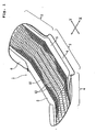
- Fig. 1 is a perspective view showing an absorbent article according to one embodiment of the present invention
- Fig. 2 is a partial plan view of a surface member of the absorbent article shown in Fig. 1
- Fig. 3A is a partial section showing a condition where continuous filaments of an upper layer is stacked on continuous filaments of a lower layer
- Fig. 3B is a partial section showing a condition where stacked continuous filaments are partially fusion bonded for forming the surface member
- Fig. 4 is a partial section showing a surface member according to another embodiment of the present invention
- Fig. 5 is a partial section showing the absorbent article and the surface member.
- An absorbent article 1 shown in Fig. 1 is a sanitary napkin, in which a width direction is defined as X direction and a longitudinal direction is defined as Y direction.
- the absorbent article 1 has an intermediate portion 2, and front and rear portions 3 and 4 lying opposite one another in the longitudinal direction and having the intermediate portion 2 located therebetween.
- side leakage preventing walls 5 and 5 extending in the longitudinal direction (Y direction) are provided.
- elastic members for exhibiting elastic contracting force in the longitudinal direction are provided to the leakage preventing walls 5 and 5.
- the main body of the absorbent article 1 is curved in the longitudinal direction, and the leakage preventing walls 5 and 5 are three-dimensionally raised from the liquid-receiving face of the main body, mainly at the intermediate portion 2.
- the main body of the absorbent article 1 is constructed to include a liquid impermeable backing sheet 7, an absorbent core (absorbent layer) 8 stacked on the backing sheet 7, and a liquid permeable surface member 10 stacked over the absorbent core 8.
- the surface member 10 is formed of at least two kinds of continuous filaments having different hydrophilicities.
- the absorbent core 8 is provided from the intermediate portion 2 to part of the front and rear portions 3 and 4.
- the surface member 10 is provided between the leakage preventing walls 5 and 5 to extend over the entire length of the main body of the absorbent article 1 (i.e., from end edge of the front portion 3, through the intermediate portion 2, to the end edge of the rear portion 4).
- Each leakage preventing wall 5 is formed of a sheet such as non-woven fabric, which is joined to the surface member 10 at a position inside of the leakage preventing wall 5, and is extended outwardly of the leakage preventing wall 5 and joined to the backing sheet 7 with a hot melt adhesive or the like, at a flap portion 6 outside of the leakage preventing wall 5.
- the surface member 10 is provided over the entire length of the main body of the absorbent article 1, but should not be limited thereto.
- the surface member 10 may be provided only at the intermediate portion 2, especially only at the center portion of the liquid-absorbing region where the absorbent core 8 is present.
- the backing sheet 7 is impermeable to liquid, and is formed of a moisture permeable (breathable) resin film, a non-woven fabric or a laminate of a resin film and a non-woven fabric.
- the absorbent core 8 is formed of a mixture of crushed pulp and SAP (superabsorbent polymer) wrapped in liquid permeable paper, air laid pulp formed into a sheet form by binder process, absorbent paper, a non-woven fabric primarily consisted of hydrophilic fibers, or the like.
- the aforementioned sheet forming the leakage preventing wall 5 may be formed of a non-woven fabric, such as through-air bonded non-woven fabric, point bonded non-woven fabric, spun bonded non-woven fabric, spun laced non-woven fabric, melt blown non-woven fabric or air laid non-woven fabric, which is preferably hydrophobic or water repellent.
- a non-woven fabric such as through-air bonded non-woven fabric, point bonded non-woven fabric, spun bonded non-woven fabric, spun laced non-woven fabric, melt blown non-woven fabric or air laid non-woven fabric, which is preferably hydrophobic or water repellent.
- the surface member 10 is formed with an upper layer 10a appearing on a liquid-receiving side surface, and a lower layer 10b positioned adjacent to the absorbent core 8.
- the upper layer 10a and the lower layer 10b are formed of first continuous filaments 11a and second continuous filaments 11b, respectively. These individual continuous filaments 11a and 11b extend in the Y direction without any interruption. In other words, the individual continuous filaments 11a and 11b extend over the entire length of the surface member 10.
- the continuous filaments 11a and 11b are crimped.
- the upper layer 10a is formed of a filament bundle (generally called as "tow"), in which the crimped continuous filaments 11a are bundled.
- the lower layer 10b is also formed of a filament bundle (generally called as “tow”), in which the crimped continuous filaments 11b are bundled.
- These filament bundles i.e., tows
- These continuous filaments 11a and 11b are occasionally referred to as tow filaments.
- the continuous filaments 11a and 11b are made of heat-fusible, hydrophobic synthetic resin.
- the continuous filaments 11a and 11b may be mono-fibers, such as those of PE (polyethylene), PP (polypropylene), PET (polyethylene terephthalate) or the like, conjugated synthetic fibers of core-sheath structure, such as those of PE/PET, PE/PP or the like, or conjugated synthetic fibers of side-by-side structure, such as those of PE/PET, PE/PP or the like.
- the continuous filaments 11a and 11b preferably contain inorganic filler for whitening, such as titanium oxide or the like, in the content of 0.5 to 10% by weight. By whitening process, the menstrual blood absorbed in the absorbent core 8 can be easily concealed from external view.
- the individual continuous filaments may have a circular or modified cross-section.
- Crimping is provided for continuous filaments upon production by means of crimper, and number of crimp is increased by pre-heating calender or hot air treatment. In the alternative, through pre-heating calender, drawing and relaxing are repeated to cause strain in orientation of resin forming continuous filaments to cause crimp in coil form.
- Opening of a bundle of crimped continuous filaments can be performed as following. While the bundle is transported between transporting rolls, tension force is applied in the direction along which the filaments extend, and then the tension force is released. These processes are repeated to separate individual continuous filaments from each other for opening.
- the bundle transported between transporting rolls is slidingly contacted with the sliding plates, and individual filaments are separated from each other by sliding contact force for opening.
- the latter method employing the sliding plates has been disclosed in commonly owned co-pending U. S. Patent Application for "METHOD AND APPARATUS FOR OPENING CONTINUOUS FILAMENTS" (claiming priority based on Japanese Patent Application No. 2000-265458 ).
- the bundle of continuous filaments thus opened has a small filament density and a large apparent width.
- the opened filament bundle is spread (widened) in the width direction to have a uniform bulkiness and to have a width substantially matching with the width of the surface member 10 shown in Fig. 1 .
- the bundle of the continuous filaments 11a for forming the upper layer 10a and the bundle of the continuous filaments 11b for forming the lower layer 10b are opened and spread, respectively, and then stacked as shown in Fig. 3A .
- the upper layer 10a and the lower layer 10b thus stacked are clamped by welding rolls, at least one of which contains a pattern of protrusions for embossing on the peripheral surface, for forming fixing lines 12.
- the continuous filaments 11a of the upper layer 10a and the continuous filaments 11b of the lower layer 10b are heat fused or welded by induction heating with ultrasonic wave to thereby form the layers 10a and 10b into a sheet.
- the individual fixing lines 12 extend across the surface member 10 in the X direction in the form of a continuous line approximated to a trigonometric curve.
- the fixing lines 12 are spaced apart from each other by a given pitch P.
- the pitch P of the fixing lines 12 is in a range of 20 to 50 mm.
- fixing lines should not be limited to the shown wavy shape but may extend in various forms, for example, in the form of straight line or V-shaped line. It is also possible to provide a plurality of short fixing lines intermittently arranged at a given interval in the X direction, so long as consideration is given to prevention of falling out of filaments.
- the surface member 10, which consists of the upper layer 10a and the lower layer 10b, has a total basis weight in a range of 5 to 100 g/m 2 , and preferably in a range of 10 to 60 g/m 2 .
- the upper layer 10a and the lower layer 10b preferably have the same basis weight, but may have different basis weights.
- the filament weight ratio of the upper layer 10a to the lower layer 10b is in a range of 5:95 to 95:5, and preferably in a range of 30:70 to 70:30.
- the average filament density is in a range 0.002 to 0.01 g/cm 3 .
- the individual continuous filaments 11a and 11b of the respective upper and lower layers 10a and 10b have a fineness in a range of 1.1 to 20 dtex, and preferably in a range of 1.1 to 11 dtex.
- number of crimp is in a range of 5 to 30 per 25.4 mm (inch), and preferably in a range of 15 to 30, and crimp modulus of elasticity is preferably greater than or equal to 70%.
- Number of crimp is based on JIS L-1015 and crimp modulus of elasticity is based on JIS L-1074. In case of the filament of a fineness less than 5.5 dtex, an initial load of 0.49 mN is applied in pulling direction, and in case of the filament of a fineness greater than or equal to 5.5 dtex, an initial load of 0.98 mN is applied in pulling direction.
- Number of crimp referred to is number of threads (peaks) per 1 inch (25.4 mm) when the initial load is applied.
- the crimp modulus of elasticity is expressed by: b - c / b - a x 100 % wherein a is a length of filament when the initial load is applied, b is a length when the crimp is stretched by applying a tension force of 4.9 mN per 1.1 dtex for 30 seconds, and c is a length as applied the initial load again after 2 minutes from releasing the tension force.
- the continuous filaments 11a of the upper layer 10a and the continuous filaments 11b of the lower layer 10b have different hydrophilicities with each other, such that the lower layer 10b has a higher hydrophilicity than that of the upper layer 10a.
- the upper layer 10a and the lower layer 10b have different filament densities with each other, such that lower layer 10b has a higher filament density than that of the upper layer 10a.
- the upper layer 10a may have a higher filament density than that of the lower layer 10b, if desired.
- a difference in hydrophilicity represents a difference in interfacial chemical nature on the filament surface, and hydrophilicity becomes higher at lower contact angle of water, in case of hydrophobic filament.
- the continuous filaments 11a of the upper layer 10a and the continuous filaments 11b of the lower layer 10b are hydrophobic filaments, such as core-sheath type conjugated fiber of PE/PP or PE/PET.
- these hydrophobic continuous filaments 11a and 11b are both treated to be hydrophilic by applying a hydrophilic oil solution onto the surfaces of the continuous filaments, a difference in hydrophilicity can be provided by using hydrophilic oil solutions having different durabilities against liquid.
- an initial hydrophilic oil solution namely a hydrophilic oil solution which can relatively easily drop off as contacting with water or other liquid.
- This kind of initial hydrophilic oil solution may be PEG modified polyester, polyoxyethylene alkyl sulfate, alkyl phosphoric ester K salt, polyoxyethylene alkyl ester, alkylsulfonate Na salt and so forth.
- a durable hydrophilic oil solution which is difficult to drop off by water or other liquid in comparison with the initial hydrophilic oil solution.
- the durable hydrophilic oil solution may be polyether ester, ether nonion, polyether modified silicon, sulfo succinate, polyoxyethylene amide ether, alkyl imidazoline type cation, polyglycerol polyester and so forth.
- the hydrophilic oil solutions being thus selected to make the durability of hydrophilic oil solution against liquid higher in the lower layer 10b than in the upper layer 10a, the lower layer 10b is permitted to have a higher hydrophilicity than that of the upper layer 10a.
- a difference in hydrophilicity may be provided by applying the same hydrophilic oil solution onto both the continuous filaments 11a and 11b of the upper and lower layers 10a and 10b, such that an application amount of hydrophilic oil solution per unit fineness (1 dtex) of continuous filaments is greater in the lower layer 10b than in the upper layer 10a.
- a difference in density can be adjusted by varying the fineness of the continuous filaments. For example, by making the fineness of the continuous filaments 11b of the lower layer 10b smaller that of the continuous filaments 11a of the upper layer 10a, the density of the lower layer 10b can be made higher than the density of the upper layer 10a.
- a difference in density may also be provided between the upper and lower layers 10a and 10b by varying number of crimp of the continuous filaments and/or by varying crimp modulus of elasticity.
- the density of the lower layer 10b can be made higher.
- the density of the lower layer 10b can be made lower.
- a difference in number of crimp greater than or equal to 10 per 25.4 mm (inch) between the upper layer 10a and the lower layer 10b it is preferred to provide a difference in crimp modulus of elasticity in the extent greater than or equal to 10% between the upper layer 10a and the lower layer 10b.
- a difference in density between the upper layer 10a and the lower layer 10b is preferably in the extent greater than or equal to 0.003 g/cm 3 .
- the surface member 10 may further comprise a liquid permeable non-woven fabric sheet 15 formed of hydrophilic fibers.
- the continuous filaments 11b of the lower layer 10b and the continuous filaments 11a of the upper layer 10a are stacked on the non-woven fabric sheet 15, and the non-woven fabric sheet 15, the lower layer 10b and the upper layer 10a are fixed together at the fixing lines 12.
- the surface member 10 may be formed with three or more layers of mutually different continuous filaments. In this case, it is preferred to gradually increase hydrophilicity toward the lower layer.
- the surface member 10 as a portion to contact the skin of a wearer, is formed of the continuous filaments. Therefore, no fiber end appears on the surface to thereby provide smooth contact feeling to the skin. Furthermore, since the continuous filaments can move independently to follow movement of the skin, the surface member 10 becomes less irritative to the skin. Also, the surface member 10 is so bulky as to provide superior cushioning characteristics.
- the lower layer 10b has a higher hydrophilicity. Therefore, the liquid applied on the surface of the surface member 10 is drawn to the lower layer 10b and thus supplied to the absorbent core 8. This results in reducing an amount of residual liquid in the upper layer 10a. If the density of the lower layer 10b is made higher than that of the upper layer 10a, the body fluid can be drawn to the lower layer 10b by capillary effect. In this case, too, an amount of residual liquid in the upper layer 10a can be reduced. Furthermore, since the upper layer 10a serves for preventing the liquid from flowing back from the absorbent core 8, the liquid absorbed in the absorbent core 8 hardly flows back toward the skin of a wearer (i.e., rewet hardly occurs).
- the density of the upper layer 10a is made higher than the density of the lower layer 10b, on the other hand, rewet-preventing property can be enhanced by the high density of the continuous filaments 11a of the upper layer 10a.
- the liquid applied to the surface member 10 is easily guided in the longitudinal direction to thereby reduce or eliminate side leakage in the width direction (X direction). Furthermore, since the continuous filaments 11a and 11b are fixed at the fixing lines 12 spaced apart from each other by the given pitch P in the longitudinal direction, spreading or propagation of the liquid in the longitudinal direction in the surface member 10 can be restricted. Thus, the liquid can be easily guided to the absorbent core 8.
- the upper layer 10a and the lower layer 10b having different hydrophilicities and densities can be formed by simply stacking and fixing opened tows of continuous filaments, manufacturing process becomes quite simple. Furthermore, since no adhesive is disposed between the upper and lower layers 10a and 10b for fixing them at the fixing lines 12, migration of liquid toward the absorbent core may not be interfered by adhesive.
- the surface member of the absorbent article may have good liquid permeability with prevention of flowing back of the liquid. Moreover, the surface member may provide soft contact feeling on the skin of a wearer and superior cushioning characteristics. Still moreover, the surface member having a difference in hydrophilicity can be easily manufactured with simple process of stacking two opened bundles of continuous filaments.
- the surface member is formed over entire surface of at least the central portion of the absorbent article, it is also possible to form the surface member into a plurality of strips arranged in parallel in spaced apart relationship.
- Such construction has been disclosed in commonly owned co-pending U. S. Patent Application, for "ABSORBENT ARTICLE HAVING FIBROUS LAYER ON SURFACE” (claiming priority based on Japanese Patent Application No. 2000-265476 ).
Abstract
Description
- The present invention relates to an absorbent article, such as sanitary napkin, disposable diaper or the like, which has a surface member formed of continuous filaments.
- Absorbent articles, such as sanitary napkins, disposable diapers or the like are generally constructed such that a liquid impermeable backing sheet is stacked on the back side of an absorbent layer, and a liquid permeable surface member is stacked on the surface side as a liquid-receiving side.
- A function of the surface member of the absorbent article is that it is required to have superior liquid permeability for permitting liquid to flow toward the absorbent layer, and to achieve high effect in preventing liquid from flowing back. Here, the phenomenon where liquid once absorbed in absorbent layer flows back toward the surface side is often referred to as "rewet".
- For example, in Japanese Unexamined Patent Publication No.
5-176954 - However, since this conventional surface member requires a process step of applying water flow, production cost becomes high. Also, since water flow is applied, basis weight becomes high and bulkiness becomes low to lack soft feeling as a surface member.
- On the other hand, in Japanese Unexamined Patent Publication No.
9-510374 - However, since this conventional surface member employs complicated structure for requiring placing two sheets in spaced apart relationship by the spacer, difficulty is encountered in manufacturing and this is less practical.
- On the other hand, as other prior art, there is a surface member in which a hydrophilic non-woven fabric is stacked below a hydrophobic non-woven fabric and these two kinds of non-woven fabric are adhered. In this surface member, permeability of body fluid is improved by liquid absorbing ability of the lower hydrophilic non-woven fabric.
- However, in this conventional surface member, since the hydrophobic non-woven fabric and the hydrophilic non-woven fabric are adhered with a hot melt type adhesive or the like, the adhesive is inherently present on the interface between the non-woven fabrics to serve to block flow of the liquid.
- On the other hand, Japanese Unexamined Utility Model Publication No.
57-13609 56-141612 - However, since the relatively bulky, hydrophobic filament layer is present on the surface of the absorbent layer, body fluid is difficult to penetrate into the absorbent layer to cause a defect that the body fluid may be retained in the filament layer.
- The present invention has been worked out in view of the problem in the prior art set forth above. It is, therefore, an object of the present invention to provide an absorbent article having a surface member which provides soft contact feeling on the skin of a wearer, high liquid permeability and high rewet-preventing property, and which is easy to manufacture.
- The present invention provides the absorbent article of independent claim 1. The dependent claims specify preferred but optional features.
- There is therefore provided an absorbent article comprising:
- a liquid permeable surface member;
- a backing sheet;
- an absorbent layer interposed between the surface member and the backing sheet, and
- the surface member having at least two layers including an upper layer located at a liquid-receiving side surface and a lower layer located adjacent to the absorbent layer, the upper layer being formed of first continuous filaments, the lower layer being formed of second continuous filaments, the first and second continuous filaments individually extending over the entire length of the surface member, and hydrophilicity of the lower layer being higher than that of the upper layer.
- For example, the first and second continuous filaments may be respectively prepared by applying a hydrophilic oil solution on surfaces of hydrophobic filaments, and durability of a hydrophilic oil solution applied to the second continuous filaments may be higher than that of a hydrophilic oil solution applied to the first continuous filaments.
- In an alternative, the first and second continuous filaments may be respectively prepared by applying a hydrophilic oil solution on surfaces of hydrophobic filaments, and the application amount of the hydrophilic oil solution to the second continuous filaments may be greater than the application amount of the hydrophilic oil solution to the first continuous filaments.
- Preferably, a density of the first continuous filaments in the upper layer is different from a density of the second continuous filaments in the lower layer. More preferably, a density of the second continuous filaments in the lower layer is higher than a density of the first continuous filaments in the upper layer. In this case, number of crimp in the first continuous filaments and number of crimp in the second continuous filaments may be respectively in a range of 5 to 30 per 25.4 mm (1 inch), but may be different from each other so that the difference in density is caused by the difference in number of crimp, and/or crimp modulus of elasticity of the first continuous filaments and crimp modulus of elasticity of the second continuous filaments may be respectively greater than or equal to 70%, but may be different from each other so that the difference in density is caused by the difference in crimp modulus of elasticity.
- In the present invention, since the surface member is formed of the continuous filaments to have a low density and a high bulk, it provides soft contact feeling to the skin of a wearer. Especially, since the individual continuous filaments extend over the entire length of the surface member to have no fiber end appearing on the surface, the surface is made so smooth.
- Moreover, since a difference in hydrophilicity is provided between the upper layer and the lower layer in the surface member of the continuous filaments, liquid permeability of the surface member is improved and the rewet-preventing effect is enhanced.
- Still moreover, the surface member having the layers of different hydrophilicities can be easily manufactured by continuously feeding the continuous filaments of different hydrophilicities and by partially fixing them.
- The present invention will be understood more fully from the detailed description given hereinafter and from the accompanying drawings of the preferred embodiment of the present invention, which, however, should not be taken to be limitative to the invention, but are for explanation and understanding only.
- In the drawings:
-
Fig. 1 is a perspective view showing an absorbent article according one embodiment of the present invention; -
Fig. 2 is a partial plan view of a surface member of the absorbent article shown inFig. 1 ; -
Fig. 3A is a partial section showing a condition where continuous filaments of an upper layer is stacked on continuous filaments of a lower layer; -
Fig. 3B is a partial section showing a condition where stacked continuous filaments are partially fusion bonded for forming the surface member; -
Fig. 4 is a partial section showing a surface member according to another embodiment of the present invention; and -
Fig. 5 is a partial section showing the absorbent article and the surface member. - The present invention will be discussed hereinafter in detail in terms of the preferred embodiment of the present invention with reference to the accompanying drawings. In the following description, numerous specific details are set forth in order to provide a thorough understanding of the present invention. It will be obvious, however, to those skilled in the art that the present invention may be practiced without these specific details. In other instance, well-known structure are not shown in detail in order to avoid unnecessary obscurity of the present invention.
-
Fig. 1 is a perspective view showing an absorbent article according to one embodiment of the present invention,Fig. 2 is a partial plan view of a surface member of the absorbent article shown inFig. 1 ,Fig. 3A is a partial section showing a condition where continuous filaments of an upper layer is stacked on continuous filaments of a lower layer,Fig. 3B is a partial section showing a condition where stacked continuous filaments are partially fusion bonded for forming the surface member,Fig. 4 is a partial section showing a surface member according to another embodiment of the present invention, andFig. 5 is a partial section showing the absorbent article and the surface member. - An absorbent article 1 shown in
Fig. 1 is a sanitary napkin, in which a width direction is defined as X direction and a longitudinal direction is defined as Y direction. The absorbent article 1 has anintermediate portion 2, and front andrear portions 3 and 4 lying opposite one another in the longitudinal direction and having theintermediate portion 2 located therebetween. At two lateral sides of a main body of the absorbent article 1, sideleakage preventing walls leakage preventing walls leakage preventing walls intermediate portion 2. - As shown in the section of
Fig. 5 , the main body of the absorbent article 1 is constructed to include a liquid impermeable backing sheet 7, an absorbent core (absorbent layer) 8 stacked on the backing sheet 7, and a liquidpermeable surface member 10 stacked over the absorbent core 8. Thesurface member 10 is formed of at least two kinds of continuous filaments having different hydrophilicities. - The absorbent core 8 is provided from the
intermediate portion 2 to part of the front andrear portions 3 and 4. Thesurface member 10 is provided between theleakage preventing walls intermediate portion 2, to the end edge of the rear portion 4). Eachleakage preventing wall 5 is formed of a sheet such as non-woven fabric, which is joined to thesurface member 10 at a position inside of theleakage preventing wall 5, and is extended outwardly of theleakage preventing wall 5 and joined to the backing sheet 7 with a hot melt adhesive or the like, at a flap portion 6 outside of theleakage preventing wall 5. - In the embodiment shown, the
surface member 10 is provided over the entire length of the main body of the absorbent article 1, but should not be limited thereto. For example, thesurface member 10 may be provided only at theintermediate portion 2, especially only at the center portion of the liquid-absorbing region where the absorbent core 8 is present. - The backing sheet 7 is impermeable to liquid, and is formed of a moisture permeable (breathable) resin film, a non-woven fabric or a laminate of a resin film and a non-woven fabric. The absorbent core 8 is formed of a mixture of crushed pulp and SAP (superabsorbent polymer) wrapped in liquid permeable paper, air laid pulp formed into a sheet form by binder process, absorbent paper, a non-woven fabric primarily consisted of hydrophilic fibers, or the like.
- The aforementioned sheet forming the leakage preventing wall 5 (also forming the flap portion 6 together with the backing sheet 7) may be formed of a non-woven fabric, such as through-air bonded non-woven fabric, point bonded non-woven fabric, spun bonded non-woven fabric, spun laced non-woven fabric, melt blown non-woven fabric or air laid non-woven fabric, which is preferably hydrophobic or water repellent.
- As shown in
Fig. 3B , thesurface member 10 is formed with anupper layer 10a appearing on a liquid-receiving side surface, and alower layer 10b positioned adjacent to the absorbent core 8. Theupper layer 10a and thelower layer 10b are formed of firstcontinuous filaments 11a and secondcontinuous filaments 11b, respectively. These individualcontinuous filaments continuous filaments surface member 10. Here, thecontinuous filaments - As described in detail hereinafter, the
upper layer 10a is formed of a filament bundle (generally called as "tow"), in which the crimpedcontinuous filaments 11a are bundled. Similarly, thelower layer 10b is also formed of a filament bundle (generally called as "tow"), in which the crimpedcontinuous filaments 11b are bundled. These filament bundles (i.e., tows) are opened, spread into a predetermined width, and joined to each other to form thesurface member 10. Thesecontinuous filaments - The
continuous filaments continuous filaments continuous filaments - Crimping is provided for continuous filaments upon production by means of crimper, and number of crimp is increased by pre-heating calender or hot air treatment. In the alternative, through pre-heating calender, drawing and relaxing are repeated to cause strain in orientation of resin forming continuous filaments to cause crimp in coil form.
- Opening of a bundle of crimped continuous filaments can be performed as following. While the bundle is transported between transporting rolls, tension force is applied in the direction along which the filaments extend, and then the tension force is released. These processes are repeated to separate individual continuous filaments from each other for opening. In the alternative, it is also possible to perform opening of the bundle by urging sliding plates onto the bundle from opposite sides. In this method, the bundle transported between transporting rolls is slidingly contacted with the sliding plates, and individual filaments are separated from each other by sliding contact force for opening. The latter method employing the sliding plates has been disclosed in commonly owned co-pending U. S. Patent Application for "METHOD AND APPARATUS FOR OPENING CONTINUOUS FILAMENTS" (claiming priority based on Japanese Patent Application No.
2000-265458 - Furthermore, the opened filament bundle is spread (widened) in the width direction to have a uniform bulkiness and to have a width substantially matching with the width of the
surface member 10 shown inFig. 1 . - As described above, the bundle of the
continuous filaments 11a for forming theupper layer 10a and the bundle of thecontinuous filaments 11b for forming thelower layer 10b are opened and spread, respectively, and then stacked as shown inFig. 3A . Theupper layer 10a and thelower layer 10b thus stacked are clamped by welding rolls, at least one of which contains a pattern of protrusions for embossing on the peripheral surface, for forming fixing lines 12. Atrespective fixing lines 12, thecontinuous filaments 11a of theupper layer 10a and thecontinuous filaments 11b of thelower layer 10b are heat fused or welded by induction heating with ultrasonic wave to thereby form thelayers - In the embodiment shown in
Figs. 1 and2 , theindividual fixing lines 12 extend across thesurface member 10 in the X direction in the form of a continuous line approximated to a trigonometric curve. In the Y direction along which the individualcontinuous filaments lines 12 are spaced apart from each other by a given pitch P. The pitch P of the fixing lines 12 is in a range of 20 to 50 mm. However, fixing lines should not be limited to the shown wavy shape but may extend in various forms, for example, in the form of straight line or V-shaped line. It is also possible to provide a plurality of short fixing lines intermittently arranged at a given interval in the X direction, so long as consideration is given to prevention of falling out of filaments. Various alternation of the short fixing line patterns are disclosed in commonly owned co-pending U. S. patent application, for "ABSORBENT ARTICLE EMPLOYING SURFACE LAYER WITH CONTINUOUS FILAMENT AND MANUFACTURING PROCESS THEREOF" (claiming priority based on Japanese Patent Application No.2000-265467 - The
surface member 10, which consists of theupper layer 10a and thelower layer 10b, has a total basis weight in a range of 5 to 100 g/m2, and preferably in a range of 10 to 60 g/m2. Theupper layer 10a and thelower layer 10b preferably have the same basis weight, but may have different basis weights. Here, the filament weight ratio of theupper layer 10a to thelower layer 10b is in a range of 5:95 to 95:5, and preferably in a range of 30:70 to 70:30. In thesurface member 10, in which theupper layer 10a and thelower layer 10b are combined, the average filament density is in a range 0.002 to 0.01 g/cm3. - The individual
continuous filaments lower layers - In the individual
continuous filaments - Number of crimp is based on JIS L-1015 and crimp modulus of elasticity is based on JIS L-1074. In case of the filament of a fineness less than 5.5 dtex, an initial load of 0.49 mN is applied in pulling direction, and in case of the filament of a fineness greater than or equal to 5.5 dtex, an initial load of 0.98 mN is applied in pulling direction. Number of crimp referred to is number of threads (peaks) per 1 inch (25.4 mm) when the initial load is applied.
- On the other hand, the crimp modulus of elasticity is expressed by:

- In the
surface member 10, thecontinuous filaments 11a of theupper layer 10a and thecontinuous filaments 11b of thelower layer 10b have different hydrophilicities with each other, such that thelower layer 10b has a higher hydrophilicity than that of theupper layer 10a. In addition, theupper layer 10a and thelower layer 10b have different filament densities with each other, such thatlower layer 10b has a higher filament density than that of theupper layer 10a. However, theupper layer 10a may have a higher filament density than that of thelower layer 10b, if desired. - Here, a difference in hydrophilicity represents a difference in interfacial chemical nature on the filament surface, and hydrophilicity becomes higher at lower contact angle of water, in case of hydrophobic filament.
- As set forth, the
continuous filaments 11a of theupper layer 10a and thecontinuous filaments 11b of thelower layer 10b are hydrophobic filaments, such as core-sheath type conjugated fiber of PE/PP or PE/PET. In the case where these hydrophobiccontinuous filaments - For example, onto the
continuous filaments 11a of theupper layer 10a, applied is an initial hydrophilic oil solution, namely a hydrophilic oil solution which can relatively easily drop off as contacting with water or other liquid. This kind of initial hydrophilic oil solution may be PEG modified polyester, polyoxyethylene alkyl sulfate, alkyl phosphoric ester K salt, polyoxyethylene alkyl ester, alkylsulfonate Na salt and so forth. On the other hand, onto thecontinuous filaments 11b of thelower layer 10b, applied is a durable hydrophilic oil solution which is difficult to drop off by water or other liquid in comparison with the initial hydrophilic oil solution. The durable hydrophilic oil solution may be polyether ester, ether nonion, polyether modified silicon, sulfo succinate, polyoxyethylene amide ether, alkyl imidazoline type cation, polyglycerol polyester and so forth. With the hydrophilic oil solutions being thus selected to make the durability of hydrophilic oil solution against liquid higher in thelower layer 10b than in theupper layer 10a, thelower layer 10b is permitted to have a higher hydrophilicity than that of theupper layer 10a. - In an alternative, a difference in hydrophilicity may be provided by applying the same hydrophilic oil solution onto both the
continuous filaments lower layers lower layer 10b than in theupper layer 10a. - Next, a difference in density can be adjusted by varying the fineness of the continuous filaments. For example, by making the fineness of the
continuous filaments 11b of thelower layer 10b smaller that of thecontinuous filaments 11a of theupper layer 10a, the density of thelower layer 10b can be made higher than the density of theupper layer 10a. - Alternatively, a difference in density may also be provided between the upper and
lower layers continuous filaments 11b of thelower layer 10b than that of thecontinuous filaments 11a of theupper layer 10a, the density of thelower layer 10b can be made higher. On the other hand, by making the crimp modulus of elasticity of thecontinuous filaments 11b of thelower layer 10b higher than the crimp modulus of elasticity of thecontinuous filaments 11a ofupper layer 10a, the density of thelower layer 10b can be made lower. - Here, it is preferred to provide a difference in number of crimp greater than or equal to 10 per 25.4 mm (inch) between the
upper layer 10a and thelower layer 10b, and it is also preferred to provide a difference in crimp modulus of elasticity in the extent greater than or equal to 10% between theupper layer 10a and thelower layer 10b. Also, a difference in density between theupper layer 10a and thelower layer 10b is preferably in the extent greater than or equal to 0.003 g/cm3. - On the other hand, as shown in
Fig. 4 , thesurface member 10 may further comprise a liquid permeablenon-woven fabric sheet 15 formed of hydrophilic fibers. In this construction, thecontinuous filaments 11b of thelower layer 10b and thecontinuous filaments 11a of theupper layer 10a are stacked on thenon-woven fabric sheet 15, and thenon-woven fabric sheet 15, thelower layer 10b and theupper layer 10a are fixed together at the fixing lines 12. - Also, it is possible to provide one or more intermediate layers of continuous filaments between the
upper layer 10a and thelower layer 10b. In other words, thesurface member 10 may be formed with three or more layers of mutually different continuous filaments. In this case, it is preferred to gradually increase hydrophilicity toward the lower layer. - In the absorbent article 1 as has been described above, the
surface member 10 as a portion to contact the skin of a wearer, is formed of the continuous filaments. Therefore, no fiber end appears on the surface to thereby provide smooth contact feeling to the skin. Furthermore, since the continuous filaments can move independently to follow movement of the skin, thesurface member 10 becomes less irritative to the skin. Also, thesurface member 10 is so bulky as to provide superior cushioning characteristics. - Furthermore, in the
surface member 10 composed of theupper layer 10a and thelower layer 10b, thelower layer 10b has a higher hydrophilicity. Therefore, the liquid applied on the surface of thesurface member 10 is drawn to thelower layer 10b and thus supplied to the absorbent core 8. This results in reducing an amount of residual liquid in theupper layer 10a. If the density of thelower layer 10b is made higher than that of theupper layer 10a, the body fluid can be drawn to thelower layer 10b by capillary effect. In this case, too, an amount of residual liquid in theupper layer 10a can be reduced. Furthermore, since theupper layer 10a serves for preventing the liquid from flowing back from the absorbent core 8, the liquid absorbed in the absorbent core 8 hardly flows back toward the skin of a wearer (i.e., rewet hardly occurs). - If the density of the
upper layer 10a is made higher than the density of thelower layer 10b, on the other hand, rewet-preventing property can be enhanced by the high density of thecontinuous filaments 11a of theupper layer 10a. - On the other hand, since the individual
continuous filaments surface member 10 is easily guided in the longitudinal direction to thereby reduce or eliminate side leakage in the width direction (X direction). Furthermore, since thecontinuous filaments lines 12 spaced apart from each other by the given pitch P in the longitudinal direction, spreading or propagation of the liquid in the longitudinal direction in thesurface member 10 can be restricted. Thus, the liquid can be easily guided to the absorbent core 8. - Since the
upper layer 10a and thelower layer 10b having different hydrophilicities and densities can be formed by simply stacking and fixing opened tows of continuous filaments, manufacturing process becomes quite simple. Furthermore, since no adhesive is disposed between the upper andlower layers lines 12, migration of liquid toward the absorbent core may not be interfered by adhesive. - As set forth above, in the present invention, the surface member of the absorbent article may have good liquid permeability with prevention of flowing back of the liquid. Moreover, the surface member may provide soft contact feeling on the skin of a wearer and superior cushioning characteristics. Still moreover, the surface member having a difference in hydrophilicity can be easily manufactured with simple process of stacking two opened bundles of continuous filaments.
- Although the present invention has been illustrated and described with respect to exemplary embodiment thereof, it should be understood by those skilled in the art that the foregoing and various other changes, omission and additions may be made therein and thereto, without departing from the spirit and scope of the present invention. Therefore, the present invention should not be understood as limited to the specific embodiment set out above but to include all possible embodiments which can be embodied within a scope encompassed and equivalent thereof with respect to the feature set out in the appended claims.
- For instance, while the surface member is formed over entire surface of at least the central portion of the absorbent article, it is also possible to form the surface member into a plurality of strips arranged in parallel in spaced apart relationship. Such construction has been disclosed in commonly owned co-pending U. S. Patent Application, for "ABSORBENT ARTICLE HAVING FIBROUS LAYER ON SURFACE" (claiming priority based on Japanese Patent Application No.
2000-265476
Claims (7)
- An absorbent article (1) comprising:a liquid permeable surface member (10);a backing sheet (7); andan absorbent layer (8) interposed between said surface member and said backing sheet,said surface member having at least two layers including an upper layer (10a) located at a liquid-receiving side surface and a lower layer (10b) located adjacent to said absorbent layer, said upper layer being formed of first continuous hydrophobic filaments (11a), said lower layer being formed of second continuous hydrophobic filaments (11b), said first and second continuous filaments individually extending over an entire length of said surface member,wherein the surfaces of said first continuous filaments (11a) have at least one compound selected from the group consisting of PEG modified polyester, polyoxyethylene alkyl sulphate, alkyl phosphoric ester K salt, polyoxyethylene alkyl ester and alkylsulfonate Na salt, andthe surfaces of said second continuous filaments (11b) have at least one compound selected from the group consisting of polyether ester, ether nonion, polyether modified silicon, sulfo succinate, polyoxyethylene amide ether, alkyl imidazoline type cation and polyglycerol polyester,so that a hydrophilicity of said lower layer is higher than a hydrophilicity of said upper layer.
- An absorbent article as claimed in Claim 1, wherein the durability of the compound on the second continuous filaments is higher than that of the compound on said first continuous filaments.
- An absorbent article as claimed in Claim 1, wherein the amount of the compound on said second continuous filaments is greater than the amount of compound on said first continuous filaments.
- An absorbent article as claimed in any preceding claim, wherein a density of said first continuous filaments in said upper layer is different from a density of said second continuous filaments in said lower layer.
- An absorbent article as claimed in Claim 4, wherein number of crimp in said first continuous filaments and number of crimp in said second continuous filaments are respectively in a range of 5 to 30 per 25.4mm (1 inch) but are different from each other so that said difference in density is caused by said difference in number of crimp.
- An absorbent article as claimed in Claim 4, wherein crimp modulus of elasticity of said first continuous filaments and crimp modulus of elasticity of said second continuous filaments are respectively greater than or equal to 70%, but are different from each other so that said difference in density is caused by said difference in crimp modulus of elasticity.
- An absorbent article as claimed in any one of Claims 4 to 6, wherein a density of said second continuous filaments in said lower layer is higher than a density of said first continuous filaments in said upper layer.
Applications Claiming Priority (2)
| Application Number | Priority Date | Filing Date | Title |
|---|---|---|---|
| JP2000265496 | 2000-09-01 | ||
| JP2000265496A JP3875009B2 (en) | 2000-09-01 | 2000-09-01 | Absorbent articles using continuous filament surface material |
Publications (3)
| Publication Number | Publication Date |
|---|---|
| EP1184020A2 EP1184020A2 (en) | 2002-03-06 |
| EP1184020A3 EP1184020A3 (en) | 2004-09-08 |
| EP1184020B1 true EP1184020B1 (en) | 2010-09-15 |
Family
ID=18752751
Family Applications (1)
| Application Number | Title | Priority Date | Filing Date |
|---|---|---|---|
| EP01307310A Expired - Lifetime EP1184020B1 (en) | 2000-09-01 | 2001-08-29 | Topsheet comprising continuous filaments for absorbent articles |
Country Status (12)
| Country | Link |
|---|---|
| US (1) | US6646178B2 (en) |
| EP (1) | EP1184020B1 (en) |
| JP (1) | JP3875009B2 (en) |
| KR (1) | KR100796225B1 (en) |
| CN (1) | CN1222264C (en) |
| AT (1) | ATE481071T1 (en) |
| BR (1) | BR0103837B1 (en) |
| CA (1) | CA2355525C (en) |
| DE (1) | DE60143068D1 (en) |
| MY (1) | MY127547A (en) |
| SG (1) | SG101459A1 (en) |
| TW (1) | TW565439B (en) |
Cited By (2)
| Publication number | Priority date | Publication date | Assignee | Title |
|---|---|---|---|---|
| US10590577B2 (en) | 2016-08-02 | 2020-03-17 | Fitesa Germany Gmbh | System and process for preparing polylactic acid nonwoven fabrics |
| US11441251B2 (en) | 2016-08-16 | 2022-09-13 | Fitesa Germany Gmbh | Nonwoven fabrics comprising polylactic acid having improved strength and toughness |
Families Citing this family (27)
| Publication number | Priority date | Publication date | Assignee | Title |
|---|---|---|---|---|
| EP1292729B1 (en) * | 2000-04-18 | 2004-07-14 | Lohmann GmbH & Co. KG | Non woven textile structure incorporating stabilized filament assemblies |
| JP3875008B2 (en) * | 2000-09-01 | 2007-01-31 | ユニ・チャーム株式会社 | Method for producing absorbent article having fiber layer on surface |
| ATE342031T1 (en) * | 2001-07-26 | 2006-11-15 | Procter & Gamble | ABSORBENT ARTICLES WITH ELASTIC TOP LAYERS |
| AR034469A1 (en) * | 2002-06-11 | 2004-02-25 | Freudenberg S A | A TRANSFER LAYER OF LIQUID FLUIDS AND ABSORBENT ARTICLE THAT INCLUDES IT. |
| JP3878085B2 (en) * | 2002-08-09 | 2007-02-07 | ユニ・チャーム株式会社 | Disposable body fluid absorbent article |
| EP1417945B1 (en) * | 2002-11-08 | 2008-12-31 | The Procter & Gamble Company | Disposable absorbent articles with masking topsheet |
| ATE319399T1 (en) * | 2002-11-08 | 2006-03-15 | Procter & Gamble | DISPOSABLE ABSORBENT ARTICLE WITH IMPROVED TOP LAYER |
| JP4140835B2 (en) * | 2003-09-19 | 2008-08-27 | 大王製紙株式会社 | Absorbent articles |
| JP4282428B2 (en) * | 2003-09-30 | 2009-06-24 | 花王株式会社 | Composite sheet |
| DE60333368D1 (en) * | 2003-10-02 | 2010-08-26 | Procter & Gamble | Absorbent article with elastomeric material |
| US20050215965A1 (en) * | 2004-03-29 | 2005-09-29 | The Procter & Gamble Company | Hydrophilic nonwovens with low retention capacity comprising cross-linked hydrophilic polymers |
| CN100512784C (en) * | 2004-04-15 | 2009-07-15 | 花王株式会社 | Surface sheet of absorptive article |
| JP4566051B2 (en) * | 2004-04-15 | 2010-10-20 | 花王株式会社 | Absorbent article surface sheet |
| JP4593986B2 (en) * | 2004-06-30 | 2010-12-08 | 大王製紙株式会社 | Absorber |
| JP4518906B2 (en) * | 2004-10-20 | 2010-08-04 | 花王株式会社 | Top sheet for absorbent articles |
| EP1845913B2 (en) * | 2004-12-29 | 2019-08-07 | SCA Hygiene Products AB | Absorbent article having improved properties of handling low-viscosity fecal materials |
| US20080167634A1 (en) * | 2005-03-23 | 2008-07-10 | Takuya Kouta | Absorbent Article |
| CN101378714A (en) * | 2006-02-01 | 2009-03-04 | 宝洁公司 | Absorbent article with urine-permeable coversheet |
| JP5133639B2 (en) * | 2007-09-21 | 2013-01-30 | 大王製紙株式会社 | Absorbent articles |
| JP5421720B2 (en) * | 2009-10-09 | 2014-02-19 | ユニ・チャーム株式会社 | Non-woven |
| EP2623308B1 (en) * | 2010-09-28 | 2015-03-25 | Sumitomo Seika Chemicals Co., Ltd. | Water absorbent sheet structure |
| DE102011018985A1 (en) * | 2011-04-28 | 2012-10-31 | Evonik Industries Ag | Elastic, absorbent hygiene product for absorption of body fluids |
| JP6005019B2 (en) * | 2013-09-30 | 2016-10-12 | 大王製紙株式会社 | Absorbent articles |
| CN104873335A (en) * | 2014-02-27 | 2015-09-02 | 金红叶纸业集团有限公司 | Absorption product and surface layer thereof |
| TR201802629T1 (en) * | 2015-08-24 | 2018-03-21 | Kao Corp | Nonwoven fabric and the absorbent article obtained therefrom. |
| WO2018129701A1 (en) | 2017-01-13 | 2018-07-19 | The Procter & Gamble Company | Nonwoven and absorbent articles having same |
| RU2713963C1 (en) * | 2017-03-15 | 2020-02-11 | Као Корпорейшн | Multilayer nonwoven material, method for its production, absorbent article and sweat absorbing sheet |
Family Cites Families (15)
| Publication number | Priority date | Publication date | Assignee | Title |
|---|---|---|---|---|
| US3949130A (en) * | 1974-01-04 | 1976-04-06 | Tuff Spun Products, Inc. | Spun bonded fabric, and articles made therefrom |
| JPS56141612A (en) | 1980-04-07 | 1981-11-05 | Hitachi Ltd | Elastic surface wave equipment |
| JPS5713609A (en) | 1980-06-28 | 1982-01-23 | Toshiba Electric Equip | Illuminator |
| JPH05176954A (en) | 1991-09-04 | 1993-07-20 | Oji Paper Co Ltd | Surface material of sanitary material, such as disposable diaper |
| US5997989A (en) * | 1992-02-03 | 1999-12-07 | Bba Nonwovens Simpsonville, Inc. | Elastic nonwoven webs and method of making same |
| CA2107170A1 (en) * | 1993-05-20 | 1994-11-21 | Kimberly-Clark Worldwide, Inc. | Lightweight nonwoven web laminates with improved comfort and barrier properties |
| US5500270A (en) | 1994-03-14 | 1996-03-19 | The Procter & Gamble Company | Capillary laminate material |
| EP0782428B1 (en) * | 1994-09-09 | 2000-03-08 | Kimberly-Clark Worldwide, Inc. | Z-direction liquid transport medium |
| JP3012475B2 (en) * | 1995-01-26 | 2000-02-21 | ユニ・チャーム株式会社 | Liquid permeable composite nonwoven fabric for body fluid absorbent articles |
| US5752945A (en) * | 1997-04-25 | 1998-05-19 | Fibertech Group, Inc. | Absorbent article with liquid transfer layer |
| SE516777C2 (en) * | 1997-12-03 | 2002-02-26 | Sca Hygiene Prod Ab | Absorbent articles with layers of continuous fibers |
| SE514391C2 (en) * | 1997-12-03 | 2001-02-19 | Sca Hygiene Prod Ab | Absorbent articles |
| EP0953323A1 (en) * | 1998-05-02 | 1999-11-03 | The Procter & Gamble Company | Disposable absorbent article having an improved topsheet |
| SE516036C2 (en) * | 2000-03-27 | 2001-11-12 | Sca Hygiene Prod Ab | Fiber-based material layer comprising at least two continuous fibers webs, so-called tow, method of making it, and absorbent articles containing the layer |
| US6488670B1 (en) * | 2000-10-27 | 2002-12-03 | Kimberly-Clark Worldwide, Inc. | Corrugated absorbent system for hygienic products |
-
2000
- 2000-09-01 JP JP2000265496A patent/JP3875009B2/en not_active Expired - Fee Related
-
2001
- 2001-08-22 US US09/934,957 patent/US6646178B2/en not_active Expired - Lifetime
- 2001-08-22 SG SG200105138A patent/SG101459A1/en unknown
- 2001-08-22 CA CA002355525A patent/CA2355525C/en not_active Expired - Fee Related
- 2001-08-23 MY MYPI20013957A patent/MY127547A/en unknown
- 2001-08-29 AT AT01307310T patent/ATE481071T1/en not_active IP Right Cessation
- 2001-08-29 EP EP01307310A patent/EP1184020B1/en not_active Expired - Lifetime
- 2001-08-29 DE DE60143068T patent/DE60143068D1/en not_active Expired - Lifetime
- 2001-08-31 TW TW090121682A patent/TW565439B/en not_active IP Right Cessation
- 2001-08-31 KR KR1020010053258A patent/KR100796225B1/en not_active IP Right Cessation
- 2001-08-31 CN CNB011393165A patent/CN1222264C/en not_active Expired - Fee Related
- 2001-08-31 BR BRPI0103837-0A patent/BR0103837B1/en not_active IP Right Cessation
Cited By (2)
| Publication number | Priority date | Publication date | Assignee | Title |
|---|---|---|---|---|
| US10590577B2 (en) | 2016-08-02 | 2020-03-17 | Fitesa Germany Gmbh | System and process for preparing polylactic acid nonwoven fabrics |
| US11441251B2 (en) | 2016-08-16 | 2022-09-13 | Fitesa Germany Gmbh | Nonwoven fabrics comprising polylactic acid having improved strength and toughness |
Also Published As
| Publication number | Publication date |
|---|---|
| MY127547A (en) | 2006-12-29 |
| CN1349787A (en) | 2002-05-22 |
| EP1184020A2 (en) | 2002-03-06 |
| TW565439B (en) | 2003-12-11 |
| CA2355525A1 (en) | 2002-03-01 |
| KR100796225B1 (en) | 2008-01-21 |
| BR0103837A (en) | 2002-05-07 |
| KR20020018599A (en) | 2002-03-08 |
| EP1184020A3 (en) | 2004-09-08 |
| CN1222264C (en) | 2005-10-12 |
| BR0103837B1 (en) | 2009-08-11 |
| SG101459A1 (en) | 2004-01-30 |
| CA2355525C (en) | 2006-05-09 |
| US20020029024A1 (en) | 2002-03-07 |
| ATE481071T1 (en) | 2010-10-15 |
| JP3875009B2 (en) | 2007-01-31 |
| DE60143068D1 (en) | 2010-10-28 |
| JP2002065738A (en) | 2002-03-05 |
| US6646178B2 (en) | 2003-11-11 |
Similar Documents
| Publication | Publication Date | Title |
|---|---|---|
| EP1184020B1 (en) | Topsheet comprising continuous filaments for absorbent articles | |
| EP1184019B1 (en) | Topsheet comprising continuous filaments for absorbent articles | |
| EP1184022B1 (en) | Absorbent article with backing sheet having continuous filaments | |
| EP1184018B1 (en) | Topsheet comprising continuous filaments for absorbent articles | |
| EP1290995B1 (en) | Absorbent article | |
| US7067711B2 (en) | Elongated absorbent article | |
| US6803334B2 (en) | Absorbent article having fibrous layer on surface | |
| KR101840995B1 (en) | Absorbent article | |
| EP0937792B1 (en) | Method of producing a fibrous layer, for an absorbent article | |
| EP0903136A2 (en) | Liquid-permeable topsheet for absorbent articles and method of making this topsheet | |
| EP1348413A1 (en) | Absorbant article and manufacturing method thereof | |
| JP4520475B2 (en) | Absorbent article using continuous filament surface structure | |
| AU6560701A (en) | Absorbent article employing surface layer with continuous filament and manufacturing process thereof | |
| EP1214922B1 (en) | Absorbent article with surface member of continuous filaments | |
| JP3564246B2 (en) | Surface layer of disposable body fluid absorbent article | |
| JP2018166946A (en) | Composite sheet and absorbent article |
Legal Events
| Date | Code | Title | Description |
|---|---|---|---|
| PUAI | Public reference made under article 153(3) epc to a published international application that has entered the european phase |
Free format text: ORIGINAL CODE: 0009012 |
|
| AK | Designated contracting states |
Kind code of ref document: A2 Designated state(s): AT BE CH CY DE DK ES FI FR GB GR IE IT LI LU MC NL PT SE TR |
|
| AX | Request for extension of the european patent |
Free format text: AL;LT;LV;MK;RO;SI |
|
| RAP1 | Party data changed (applicant data changed or rights of an application transferred) |
Owner name: UNI-CHARM CORPORATION |
|
| PUAL | Search report despatched |
Free format text: ORIGINAL CODE: 0009013 |
|
| AK | Designated contracting states |
Kind code of ref document: A3 Designated state(s): AT BE CH CY DE DK ES FI FR GB GR IE IT LI LU MC NL PT SE TR |
|
| AX | Request for extension of the european patent |
Extension state: AL LT LV MK RO SI |
|
| 17P | Request for examination filed |
Effective date: 20050111 |
|
| AKX | Designation fees paid |
Designated state(s): AT BE CH CY DE DK ES FI FR GB GR IE IT LI LU MC NL PT SE TR |
|
| 17Q | First examination report despatched |
Effective date: 20070411 |
|
| GRAJ | Information related to disapproval of communication of intention to grant by the applicant or resumption of examination proceedings by the epo deleted |
Free format text: ORIGINAL CODE: EPIDOSDIGR1 |
|
| GRAP | Despatch of communication of intention to grant a patent |
Free format text: ORIGINAL CODE: EPIDOSNIGR1 |
|
| GRAP | Despatch of communication of intention to grant a patent |
Free format text: ORIGINAL CODE: EPIDOSNIGR1 |
|
| GRAS | Grant fee paid |
Free format text: ORIGINAL CODE: EPIDOSNIGR3 |
|
| GRAA | (expected) grant |
Free format text: ORIGINAL CODE: 0009210 |
|
| AK | Designated contracting states |
Kind code of ref document: B1 Designated state(s): AT BE CH CY DE DK ES FI FR GB GR IE IT LI LU MC NL PT SE TR |
|
| REG | Reference to a national code |
Ref country code: GB Ref legal event code: FG4D Ref country code: CH Ref legal event code: EP |
|
| REG | Reference to a national code |
Ref country code: IE Ref legal event code: FG4D |
|
| REF | Corresponds to: |
Ref document number: 60143068 Country of ref document: DE Date of ref document: 20101028 Kind code of ref document: P |
|
| REG | Reference to a national code |
Ref country code: NL Ref legal event code: VDEP Effective date: 20100915 |
|
| PG25 | Lapsed in a contracting state [announced via postgrant information from national office to epo] |
Ref country code: FI Free format text: LAPSE BECAUSE OF FAILURE TO SUBMIT A TRANSLATION OF THE DESCRIPTION OR TO PAY THE FEE WITHIN THE PRESCRIBED TIME-LIMIT Effective date: 20100915 Ref country code: AT Free format text: LAPSE BECAUSE OF FAILURE TO SUBMIT A TRANSLATION OF THE DESCRIPTION OR TO PAY THE FEE WITHIN THE PRESCRIBED TIME-LIMIT Effective date: 20100915 |
|
| PG25 | Lapsed in a contracting state [announced via postgrant information from national office to epo] |
Ref country code: CY Free format text: LAPSE BECAUSE OF FAILURE TO SUBMIT A TRANSLATION OF THE DESCRIPTION OR TO PAY THE FEE WITHIN THE PRESCRIBED TIME-LIMIT Effective date: 20100915 |
|
| PG25 | Lapsed in a contracting state [announced via postgrant information from national office to epo] |
Ref country code: SE Free format text: LAPSE BECAUSE OF FAILURE TO SUBMIT A TRANSLATION OF THE DESCRIPTION OR TO PAY THE FEE WITHIN THE PRESCRIBED TIME-LIMIT Effective date: 20100915 Ref country code: GR Free format text: LAPSE BECAUSE OF FAILURE TO SUBMIT A TRANSLATION OF THE DESCRIPTION OR TO PAY THE FEE WITHIN THE PRESCRIBED TIME-LIMIT Effective date: 20101216 |
|
| PG25 | Lapsed in a contracting state [announced via postgrant information from national office to epo] |
Ref country code: NL Free format text: LAPSE BECAUSE OF FAILURE TO SUBMIT A TRANSLATION OF THE DESCRIPTION OR TO PAY THE FEE WITHIN THE PRESCRIBED TIME-LIMIT Effective date: 20100915 Ref country code: IT Free format text: LAPSE BECAUSE OF FAILURE TO SUBMIT A TRANSLATION OF THE DESCRIPTION OR TO PAY THE FEE WITHIN THE PRESCRIBED TIME-LIMIT Effective date: 20100915 Ref country code: PT Free format text: LAPSE BECAUSE OF FAILURE TO SUBMIT A TRANSLATION OF THE DESCRIPTION OR TO PAY THE FEE WITHIN THE PRESCRIBED TIME-LIMIT Effective date: 20110117 |
|
| PG25 | Lapsed in a contracting state [announced via postgrant information from national office to epo] |
Ref country code: BE Free format text: LAPSE BECAUSE OF FAILURE TO SUBMIT A TRANSLATION OF THE DESCRIPTION OR TO PAY THE FEE WITHIN THE PRESCRIBED TIME-LIMIT Effective date: 20100915 Ref country code: ES Free format text: LAPSE BECAUSE OF FAILURE TO SUBMIT A TRANSLATION OF THE DESCRIPTION OR TO PAY THE FEE WITHIN THE PRESCRIBED TIME-LIMIT Effective date: 20101226 |
|
| PLBE | No opposition filed within time limit |
Free format text: ORIGINAL CODE: 0009261 |
|
| STAA | Information on the status of an ep patent application or granted ep patent |
Free format text: STATUS: NO OPPOSITION FILED WITHIN TIME LIMIT |
|
| 26N | No opposition filed |
Effective date: 20110616 |
|
| PG25 | Lapsed in a contracting state [announced via postgrant information from national office to epo] |
Ref country code: DK Free format text: LAPSE BECAUSE OF FAILURE TO SUBMIT A TRANSLATION OF THE DESCRIPTION OR TO PAY THE FEE WITHIN THE PRESCRIBED TIME-LIMIT Effective date: 20100915 |
|
| REG | Reference to a national code |
Ref country code: DE Ref legal event code: R097 Ref document number: 60143068 Country of ref document: DE Effective date: 20110616 |
|
| PG25 | Lapsed in a contracting state [announced via postgrant information from national office to epo] |
Ref country code: MC Free format text: LAPSE BECAUSE OF NON-PAYMENT OF DUE FEES Effective date: 20110831 |
|
| REG | Reference to a national code |
Ref country code: CH Ref legal event code: PL |
|
| PG25 | Lapsed in a contracting state [announced via postgrant information from national office to epo] |
Ref country code: LI Free format text: LAPSE BECAUSE OF NON-PAYMENT OF DUE FEES Effective date: 20110831 Ref country code: CH Free format text: LAPSE BECAUSE OF NON-PAYMENT OF DUE FEES Effective date: 20110831 |
|
| REG | Reference to a national code |
Ref country code: IE Ref legal event code: MM4A |
|
| PG25 | Lapsed in a contracting state [announced via postgrant information from national office to epo] |
Ref country code: IE Free format text: LAPSE BECAUSE OF NON-PAYMENT OF DUE FEES Effective date: 20110829 |
|
| PG25 | Lapsed in a contracting state [announced via postgrant information from national office to epo] |
Ref country code: LU Free format text: LAPSE BECAUSE OF NON-PAYMENT OF DUE FEES Effective date: 20110829 |
|
| PG25 | Lapsed in a contracting state [announced via postgrant information from national office to epo] |
Ref country code: TR Free format text: LAPSE BECAUSE OF FAILURE TO SUBMIT A TRANSLATION OF THE DESCRIPTION OR TO PAY THE FEE WITHIN THE PRESCRIBED TIME-LIMIT Effective date: 20100915 |
|
| REG | Reference to a national code |
Ref country code: FR Ref legal event code: PLFP Year of fee payment: 16 |
|
| REG | Reference to a national code |
Ref country code: FR Ref legal event code: PLFP Year of fee payment: 17 |
|
| REG | Reference to a national code |
Ref country code: FR Ref legal event code: PLFP Year of fee payment: 18 |
|
| PGFP | Annual fee paid to national office [announced via postgrant information from national office to epo] |
Ref country code: GB Payment date: 20200826 Year of fee payment: 20 Ref country code: FR Payment date: 20200821 Year of fee payment: 20 Ref country code: DE Payment date: 20200824 Year of fee payment: 20 |
|
| REG | Reference to a national code |
Ref country code: DE Ref legal event code: R071 Ref document number: 60143068 Country of ref document: DE |
|
| REG | Reference to a national code |
Ref country code: GB Ref legal event code: PE20 Expiry date: 20210828 |
|
| PG25 | Lapsed in a contracting state [announced via postgrant information from national office to epo] |
Ref country code: GB Free format text: LAPSE BECAUSE OF EXPIRATION OF PROTECTION Effective date: 20210828 |