EP1182688A1 - Low pressure discharge lamp with a double helix shape - Google Patents
Low pressure discharge lamp with a double helix shape Download PDFInfo
- Publication number
- EP1182688A1 EP1182688A1 EP01306724A EP01306724A EP1182688A1 EP 1182688 A1 EP1182688 A1 EP 1182688A1 EP 01306724 A EP01306724 A EP 01306724A EP 01306724 A EP01306724 A EP 01306724A EP 1182688 A1 EP1182688 A1 EP 1182688A1
- Authority
- EP
- European Patent Office
- Prior art keywords
- lamp
- end portions
- discharge
- envelope
- discharge lamp
- Prior art date
- Legal status (The legal status is an assumption and is not a legal conclusion. Google has not performed a legal analysis and makes no representation as to the accuracy of the status listed.)
- Withdrawn
Links
- 238000007789 sealing Methods 0.000 claims abstract description 21
- OAICVXFJPJFONN-UHFFFAOYSA-N Phosphorus Chemical compound [P] OAICVXFJPJFONN-UHFFFAOYSA-N 0.000 claims abstract description 10
- 239000011248 coating agent Substances 0.000 claims abstract description 9
- 238000000576 coating method Methods 0.000 claims abstract description 9
- 238000000071 blow moulding Methods 0.000 claims description 6
- 208000028659 discharge Diseases 0.000 description 60
- QSHDDOUJBYECFT-UHFFFAOYSA-N mercury Chemical compound [Hg] QSHDDOUJBYECFT-UHFFFAOYSA-N 0.000 description 11
- 238000004519 manufacturing process Methods 0.000 description 10
- 238000005452 bending Methods 0.000 description 6
- 238000010276 construction Methods 0.000 description 5
- 229910052753 mercury Inorganic materials 0.000 description 5
- 239000007789 gas Substances 0.000 description 4
- 239000011521 glass Substances 0.000 description 4
- XKRFYHLGVUSROY-UHFFFAOYSA-N Argon Chemical compound [Ar] XKRFYHLGVUSROY-UHFFFAOYSA-N 0.000 description 2
- 238000005336 cracking Methods 0.000 description 2
- 238000010586 diagram Methods 0.000 description 2
- 238000005304 joining Methods 0.000 description 2
- 230000005855 radiation Effects 0.000 description 2
- 241000143973 Libytheinae Species 0.000 description 1
- 229910052786 argon Inorganic materials 0.000 description 1
- 230000015572 biosynthetic process Effects 0.000 description 1
- 230000003247 decreasing effect Effects 0.000 description 1
- 238000010438 heat treatment Methods 0.000 description 1
- 239000007788 liquid Substances 0.000 description 1
- 239000007791 liquid phase Substances 0.000 description 1
- 238000002844 melting Methods 0.000 description 1
- 230000008018 melting Effects 0.000 description 1
- 238000000034 method Methods 0.000 description 1
- 229910052756 noble gas Inorganic materials 0.000 description 1
- 239000002244 precipitate Substances 0.000 description 1
- 210000004894 snout Anatomy 0.000 description 1
- 230000006641 stabilisation Effects 0.000 description 1
- 238000011105 stabilization Methods 0.000 description 1
- 208000012313 wound discharge Diseases 0.000 description 1
Images


Classifications
-
- H—ELECTRICITY
- H01—ELECTRIC ELEMENTS
- H01J—ELECTRIC DISCHARGE TUBES OR DISCHARGE LAMPS
- H01J61/00—Gas-discharge or vapour-discharge lamps
- H01J61/02—Details
- H01J61/30—Vessels; Containers
- H01J61/32—Special longitudinal shape, e.g. for advertising purposes
- H01J61/327—"Compact"-lamps, i.e. lamps having a folded discharge path
Definitions
- This invention relates to a low pressure discharge lamp, and , more particularly, to a compact fluorescent lamp structure with a double helix shape.
- mercury dosed to the fill gas of the lamp is used for light generation.
- phosphor coating is provided on the interior surface of the discharge envelope.
- Lamp manufacturers attempt to set the partial pressure of mercury vapor according to the highest radiation resonance line in order to accomplish the highest luminous output at the voltage and current density applied to the electrodes of the discharge envelope and to stabilize this partial pressure, as well.
- the adjustment and stabilization of mercury vapor partial pressure at a configuration of low pressure discharge lamps known so far is feasible by setting the temperature of a specially formed cold spot of the discharge envelope which is the coldest point of the lamp.
- a helical configuration of low pressure discharge lamp is described in a patent issued in the late German Democratic Republic with No. 212 843.
- the discharge envelope of this lamp comprises a linear tube section and a helical tube section wound around the linear section with at least one loop.
- the linear section is connected to the helical section through a bridging at the upper end of the envelope further off the base of the lamp.
- This configuration of compact fluorescent lamp did not become a practical application because there would have been a need for two production lines for manufacturing the two different tube sections, which would have increased the expenses.
- Formation of the cold spot is also difficult at this configuration since this can be accomplished only by means of lengthening the upper sealed part of the linear tube section in the vicinity of the bridging which results in poor esthetical appearance.
- the part of the helical section which connects to the linear section through the bridging has to be bent under a relatively sharp angle so that it can be connected to the linear tube section positioned in the central axis of the lamp. This sharp angle bending might cause peeling of the phosphor coating on the inner curve and cracked phosphor coating on the outer curve of the bent tube section which throw difficulties in the way of faultless manufacturing.
- a double helix configuration of a low pressure discharge lamp is described in German Offenlegungsschrift DE 41 33 077 A1.
- the discharge envelope of the discharge lamp is helical in shape.
- the ends of the tube sections are bent towards the central axis of the helix and the ends are melted together through a joining section of enlarged diameter.
- This enlarged diameter section is the cold spot of the lamp.
- U.S. Patent No. 5 680 005 describes also a low pressure discharge lamp with a double helix configuration.
- the joining section of the two helical parts is formed of a slightly expanded linear tube that joins to the helically shaped tube parts through 180° bending.
- the expanded linear tube can be considered as cold spot.
- the tube diameter in the 180° bending is reduced, thus the discharge arc warms up the walls of the tube, and the generated heat is conducted to the linear section making its operation as cold spot difficult. Due to the indefinite cold spot, the partial pressure of mercury vapor cannot be set to the optimum level and the luminous output of the discharge lamp does not attain the highest possible value.
- a low pressure discharge lamp with a double helix shape comprises a lamp base and an envelope connected to the lamp base.
- the envelope has a phosphor coating on an interior surface thereof, and contains a gas fill energizable to a discharge state by electrical voltage.
- the envelope includes discharge tube sections which are wound about a longitudinal axis and fitted into each other as a double-start thread.
- the discharge tube sections have first end portions and second end portions.
- the first end portions are closer to the lamp base and each have a gas-tight sealing and electrodes in the sealing for receiving the electric voltage.
- the second end portions are farther off the lamp base and each have a gas-tight sealing.
- These second end portions are bent inwards from a pitch of the helix and extend next to each other spaced apart by a clearance.
- a passage is formed between said second end portions. The passage is spaced apart by a distance from the sealing of each said second end portion.
- This construction has the advantage over the lamp of German Democratic Republic Patent No. 212 843 that its envelope can be manufactured less expensively using only one production line and has a good esthetic appearance.
- a further advantage is over the lamp described in DE 41 33 077 A1 that this construction when manufactured is less susceptible to phosphor peeling and cracking which results in a smaller scrap rate.
- a still further advantage is also over the lamp disclosed by U.S. Patent No. 5 680 005, that this construction provides a more stable operation and higher luminous output due to well-defined cold spots.
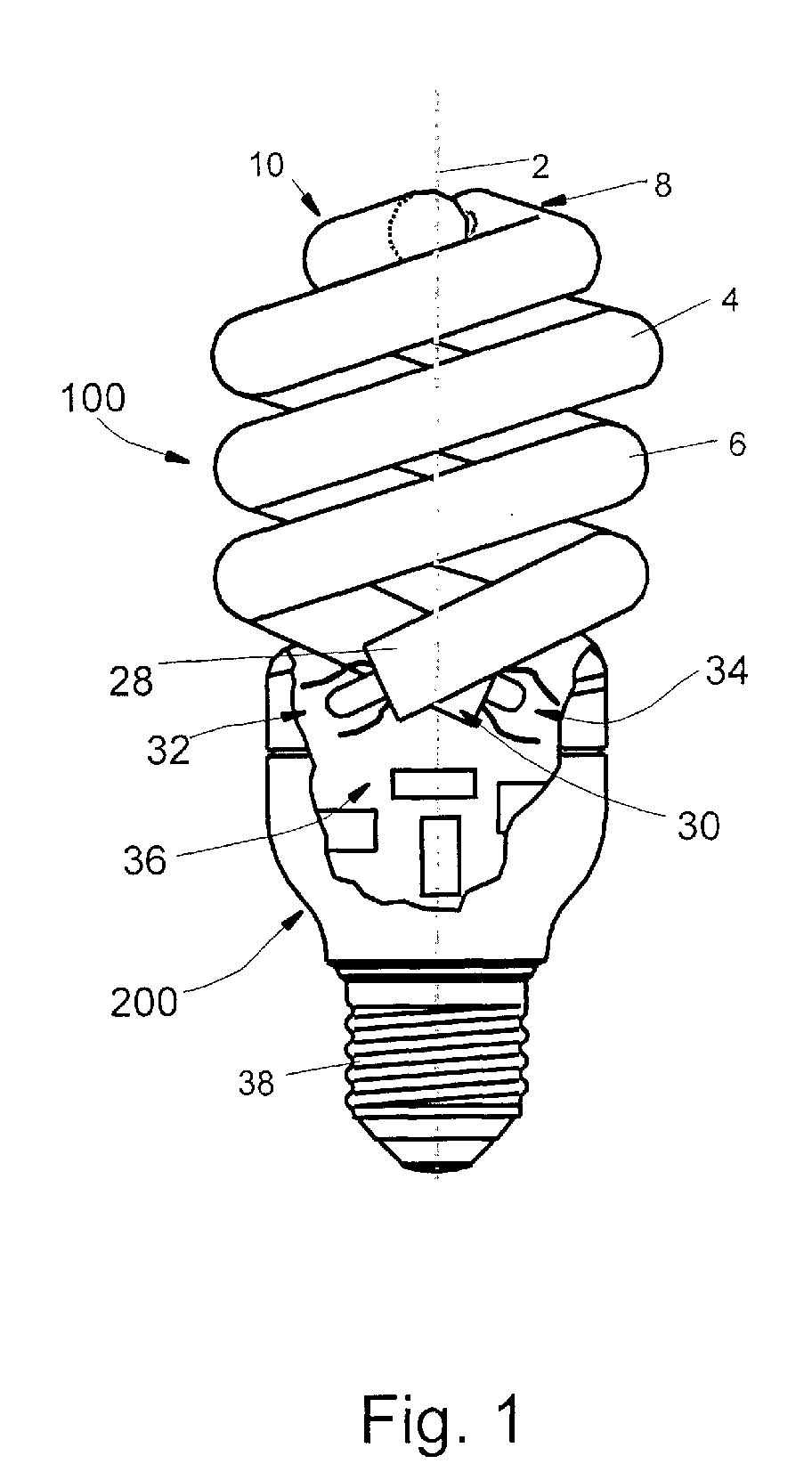
- Fig. 1 shows an embodiment of the low pressure discharge lamp having a double helix shape with an envelope 100 and mounted with a base 200 schematically.
- the mechanical and electrical connection of the low pressure discharge lamp to a suitable socket (not shown) is enabled by a threaded section 38 of the lamp base 200.
- the envelope 100 includes two discharge tube sections 4, 6 wound helically about a longitudinal axis 2.
- the pitch of the coiled discharge tube sections 4, 6 is such that it allows the discharge tube sections to be fitted into each other, i. e. there is sufficient space between the turns of one discharge tube section 4 or 6 to accept the turns of the other discharge tube section 6 or 4, respectively.
- the helically coiled discharge tube sections 4, 6 are fitted to each other as a double start thread about the longitudinal axis 2, i. e. the envelope 100 has a shape of double helix.
- the discharge tube sections 4, 6 have first end portions 28, 30 that are closer to the lamp base 200, and second end portions 8, 10 that are farther off the lamp base 200.
- the second end portions 8, 10 of the discharge tube sections 4, 6 are bent inwards diametrically opposite to each other from the pitch of the helix along a curve which is smaller than the curve of the helically wound discharge tube sections 4, 6.
- the second end portions 8, 10 bent inwardly from the pitch of the helix or, in the embodiment shown in Fig. 2, their at least approximately straight tube sections 12, 14 extend next to and overlap each other.
- the second end portions 8, 10 or their straight tube sections 12, 14 are spaced apart from each other by a clearance 24.
- the second end portions 8, 10 are sealed in a gas-tight manner, and a passage enabling a continuous discharge path is formed between the second end portions 8, 10 or, in the embodiment of Fig. 2, between the straight tube sections 12, 14 of the second end portions 8, 10.
- the passage is spaced apart from the sealing 16, 18 of each second end portion by a distance S.
- the first end portions 28, 30 of the discharge tube sections 4, 6 being closer to the lamp base 200 are sealed in a gas-tight manner, and electrodes 32, 34 are set into these seals that connect to a ballast circuit 36.
- the way of connecting the electrodes 32, 34 to the ballast circuit 36 is not detailed here, it is known to experts skilled in the art.
- the ballast circuit 36 located in the lamp base 200 generates an electrical voltage of appropriate parameters from the mains voltage which drives a gas fill in the envelope 100 in a state of discharge.
- the gas fill can be a noble gas, for example argon, to which mercury is dosed for the generation of visible light.
- Mercury radiates UV light primarily. In order to transform this UV radiation to visible light, the interior surface of the envelope 100 is provided with phosphor coating.
- the passage between the discharge tube sections 4, 6, that enables a continuous discharge arc path is a bridging 20.
- This bridging can be made by a method known from compact fluorescent lamp manufacturing.
- the discharge tube sections 4, 6 which can be made of soft glass are melted at a distance from their sealing with a thin flame. The melted spots are punctured with a blow and the snouts obtained are put together.
- the well-defined cold spot allows mercury vapor partial pressure to be set to a value corresponding to the highest intensity 253,4 nanometer resonance line of the mercury. An amount of the mercury vapor above its liquid phase giving rise to a higher partial pressure than the optimum one precipitates in the cold spot. On the other hand, when the mercury vapor partial pressure is lower than the optimum one, an appropriate amount of the liquid mercury condensed in the cold spot evaporates. Based on this, the luminous output of the low pressure discharge lamp can be set to the maximum value at a given power input.
- the double cold spot construction according to the present invention enables the discharge operation of the lamp to be more stable compared to the operation of low pressure discharge lamps with double helix shape known so far.
- a 37°C temperature of the cold spot desired at 24°C ambient temperature is influenced not only by the positioning of the discharge path in the envelope 100 but the outer air flow carrying the heat generated by the discharge lamp. This air flow heats the cold spots on the top of the envelope 100 when the lamp is positioned vertically such as seen in Fig. 1 (base down position).
- the enlarged cold spot surface is heated by the hot air flow less and the probability of heating both cold spots equally is small thus a well-defined cold spot will be formed by all means.
- the second end portions 8, 10 of the discharge tube sections 4, 6 of the lamp according to the present invention are bent with a larger angle inwardly next to the longitudinal axis 2.
- the second end portions 8, 10 pass by the longitudinal axis at a distance. Due to the bending of the tube ends with a larger angle, the risk that the phosphor coating peels on the inner curve and cracks on the outer curve is reduced as a consequence of which the scrap rate of production will be decreased, too.
- sealing 16, 18 of the second end portions 8, 10 of the discharge tube sections 4, 6 is at least approximately hemispherical in shape.
- FIGs. 3 and 4 show a further embodiment of the low pressure discharge lamp envelope with a double helix shape where the second end portions 8, 10 of the discharge tube sections 4, 6 bent inwardly next to the longitudinal axis 2 are formed with blow molding.
- the structure of the envelope 100 is similar to that shown in Figs. 1 and 2.
- the identical envelope portions are denoted with the same reference signs, and their description is not repeated herein.
- the passage between the second end portions 8, 10 is formed by a duct 26 made with blow molding.
- a straight soft glass tube may be used to start with, a middle section of which is afterwards heated to the melting point of the glass. Subsequently, this middle section is placed into a form worked out with a shape and size corresponding to those of the second end portions 8, 10, their sealing 16, 18 and the duct 26 enabling the continuous discharge path. The second end portions 8, 10, the sealing 16, 18 and the duct 26 are then formed with an air blow. The whole glass body having been formed at the middle section thereof is then warmed up, and finally the tube legs projecting from the middle section are bent on a form with double-start thread.
- Fig. 5 shows a plug-in embodiment of the low pressure discharge lamp with a double helix shape.
- the passage between the discharge tube sections 4, 6 coiled about the longitudinal axis 2 of the lamp is formed with blow molding but an envelope 100 the passage of which is formed with bridging is obviously also applicable.
- the ballast circuit is not mounted in the lamp at this embodiment but it forms a separate structural unit.
- a plug 40 projecting from the lamp base 200 serves for connecting the low pressure discharge lamp in a socket (not shown herein) mechanically, pins 42, 44 enable electrical connection to the ballast circuit (not shown herein) which forms a separate structural unit.
- Fig. 6 which is a diagram of the luminous output measured in lumens vs. the ambient temperature measured in °C, illustrates the test results.
- a dotted line shows the luminous output of a prior art lamp constructed without the passage between the end portions of the discharge tube sections similarly to the lamp disclosed by U.S. Patent 5 680 005.
- a continuous line shows the luminous output of a lamp constructed with the bridging 20. The rated power of both lamps was 32W.
Landscapes
- Vessels And Coating Films For Discharge Lamps (AREA)
Abstract
Description
- This invention relates to a low pressure discharge lamp, and , more particularly, to a compact fluorescent lamp structure with a double helix shape.
- In low pressure discharge lamps, mercury dosed to the fill gas of the lamp is used for light generation. In order to produce visible light, phosphor coating is provided on the interior surface of the discharge envelope. Lamp manufacturers attempt to set the partial pressure of mercury vapor according to the highest radiation resonance line in order to accomplish the highest luminous output at the voltage and current density applied to the electrodes of the discharge envelope and to stabilize this partial pressure, as well. The adjustment and stabilization of mercury vapor partial pressure at a configuration of low pressure discharge lamps known so far is feasible by setting the temperature of a specially formed cold spot of the discharge envelope which is the coldest point of the lamp.
- A helical configuration of low pressure discharge lamp is described in a patent issued in the late German Democratic Republic with No. 212 843. The discharge envelope of this lamp comprises a linear tube section and a helical tube section wound around the linear section with at least one loop. The linear section is connected to the helical section through a bridging at the upper end of the envelope further off the base of the lamp. This configuration of compact fluorescent lamp did not become a practical application because there would have been a need for two production lines for manufacturing the two different tube sections, which would have increased the expenses.
- Formation of the cold spot is also difficult at this configuration since this can be accomplished only by means of lengthening the upper sealed part of the linear tube section in the vicinity of the bridging which results in poor esthetical appearance. The part of the helical section which connects to the linear section through the bridging has to be bent under a relatively sharp angle so that it can be connected to the linear tube section positioned in the central axis of the lamp. This sharp angle bending might cause peeling of the phosphor coating on the inner curve and cracked phosphor coating on the outer curve of the bent tube section which throw difficulties in the way of faultless manufacturing.
- A double helix configuration of a low pressure discharge lamp is described in German Offenlegungsschrift DE 41 33 077 A1. The discharge envelope of the discharge lamp is helical in shape. At the top of the envelope, the ends of the tube sections are bent towards the central axis of the helix and the ends are melted together through a joining section of enlarged diameter. This enlarged diameter section is the cold spot of the lamp. When manufacturing this tube configuration, there is no need for two bending machines since the helical sections to be melted together are of identical shape. Nevertheless, bending under a relatively sharp angle makes faultless manufacturing also difficult due to the peeling and cracking of the phosphor coating.
- U.S. Patent No. 5 680 005 describes also a low pressure discharge lamp with a double helix configuration. The joining section of the two helical parts is formed of a slightly expanded linear tube that joins to the helically shaped tube parts through 180° bending. At this configuration of low pressure discharge lamp, the expanded linear tube can be considered as cold spot. However, the tube diameter in the 180° bending is reduced, thus the discharge arc warms up the walls of the tube, and the generated heat is conducted to the linear section making its operation as cold spot difficult. Due to the indefinite cold spot, the partial pressure of mercury vapor cannot be set to the optimum level and the luminous output of the discharge lamp does not attain the highest possible value.
- Thus there is a particular need for a low pressure discharge lamp with a double helix shape which has a well-defined cold spot, a good esthetic appearance, and the manufacturing process of which is conducive to the faultless production.
- In an exemplary embodiment of the present invention, a low pressure discharge lamp with a double helix shape comprises a lamp base and an envelope connected to the lamp base. The envelope has a phosphor coating on an interior surface thereof, and contains a gas fill energizable to a discharge state by electrical voltage. The envelope includes discharge tube sections which are wound about a longitudinal axis and fitted into each other as a double-start thread. The discharge tube sections have first end portions and second end portions. The first end portions are closer to the lamp base and each have a gas-tight sealing and electrodes in the sealing for receiving the electric voltage. The second end portions are farther off the lamp base and each have a gas-tight sealing. These second end portions are bent inwards from a pitch of the helix and extend next to each other spaced apart by a clearance. A passage is formed between said second end portions. The passage is spaced apart by a distance from the sealing of each said second end portion.
- This construction has the advantage over the lamp of German Democratic Republic Patent No. 212 843 that its envelope can be manufactured less expensively using only one production line and has a good esthetic appearance. A further advantage is over the lamp described in DE 41 33 077 A1 that this construction when manufactured is less susceptible to phosphor peeling and cracking which results in a smaller scrap rate. A still further advantage is also over the lamp disclosed by U.S. Patent No. 5 680 005, that this construction provides a more stable operation and higher luminous output due to well-defined cold spots.
- The invention will now be described in greater detail, by way of example, with reference to the drawings, in which:-
- Fig. 1 is a partly broken out front view of an embodiment of a low pressure discharge lamp of double helix shape constructed with bridging;
- Fig. 2 is a top view of an envelope of the low pressure discharge lamp of Fig. 1;
- Fig. 3 is a front view of a further embodiment of the low pressure discharge lamp envelope with a double helix shape made by blow molding;
- Fig. 4 is a top view of the low pressure discharge lamp envelope shown in Fig. 3;
- Fig. 5 is a front view of a still further embodiment of the low pressure discharge lamp mounted with the envelope shown in Figs. 3 and 4.
- Fig. 6 is a diagram showing luminous output of a prior art lamp and a lamp constructed with bridging vs. ambient temperature.
-
- Fig. 1 shows an embodiment of the low pressure discharge lamp having a double helix shape with an
envelope 100 and mounted with abase 200 schematically. The mechanical and electrical connection of the low pressure discharge lamp to a suitable socket (not shown) is enabled by a threadedsection 38 of thelamp base 200. Theenvelope 100 includes twodischarge tube sections longitudinal axis 2. The pitch of the coileddischarge tube sections discharge tube section discharge tube section discharge tube sections longitudinal axis 2, i. e. theenvelope 100 has a shape of double helix. Thedischarge tube sections first end portions lamp base 200, andsecond end portions lamp base 200. - As it is seen in a top view of the
envelope 100 shown in Fig. 2, thesecond end portions discharge tube sections discharge tube sections second end portions straight tube sections second end portions straight tube sections clearance 24. - The
second end portions second end portions straight tube sections second end portions - Returning back to Fig. 1, the
first end portions discharge tube sections lamp base 200 are sealed in a gas-tight manner, andelectrodes ballast circuit 36. The way of connecting theelectrodes ballast circuit 36 is not detailed here, it is known to experts skilled in the art. - The
ballast circuit 36 located in thelamp base 200 generates an electrical voltage of appropriate parameters from the mains voltage which drives a gas fill in theenvelope 100 in a state of discharge. The gas fill can be a noble gas, for example argon, to which mercury is dosed for the generation of visible light. Mercury radiates UV light primarily. In order to transform this UV radiation to visible light, the interior surface of theenvelope 100 is provided with phosphor coating. - In the embodiment shown in Figs. 1 and 2, the passage between the
discharge tube sections bridging 20. This bridging can be made by a method known from compact fluorescent lamp manufacturing. Thedischarge tube sections - Due to the structure of the
envelope 100 described above, two well-defined cold spots are formed in the vicinity of the sealing 16, 18 of thesecond end portions longitudinal axis 2. Experience shows that it is advantageous with respect to forming well-defined cold spots if the distance S between an axis of the passage and a top of the sealing 16, 18 of thesecond end portions - The well-defined cold spot allows mercury vapor partial pressure to be set to a value corresponding to the
highest intensity 253,4 nanometer resonance line of the mercury. An amount of the mercury vapor above its liquid phase giving rise to a higher partial pressure than the optimum one precipitates in the cold spot. On the other hand, when the mercury vapor partial pressure is lower than the optimum one, an appropriate amount of the liquid mercury condensed in the cold spot evaporates. Based on this, the luminous output of the low pressure discharge lamp can be set to the maximum value at a given power input. - The double cold spot construction according to the present invention enables the discharge operation of the lamp to be more stable compared to the operation of low pressure discharge lamps with double helix shape known so far. A 37°C temperature of the cold spot desired at 24°C ambient temperature is influenced not only by the positioning of the discharge path in the
envelope 100 but the outer air flow carrying the heat generated by the discharge lamp. This air flow heats the cold spots on the top of theenvelope 100 when the lamp is positioned vertically such as seen in Fig. 1 (base down position). In the event that the lamp has two cold spots, the enlarged cold spot surface is heated by the hot air flow less and the probability of heating both cold spots equally is small thus a well-defined cold spot will be formed by all means. - Compared to the low pressure discharge lamp with double helix shape described in German Offenlegungsschrift No. DE 41 33 077 A1, the
second end portions discharge tube sections longitudinal axis 2. Thesecond end portions - It is advantageous esthetically that the sealing 16, 18 of the
second end portions discharge tube sections - Referring now to Figs. 3 and 4, these figures show a further embodiment of the low pressure discharge lamp envelope with a double helix shape where the
second end portions discharge tube sections longitudinal axis 2 are formed with blow molding. The structure of theenvelope 100 is similar to that shown in Figs. 1 and 2. The identical envelope portions are denoted with the same reference signs, and their description is not repeated herein. However, the passage between thesecond end portions duct 26 made with blow molding. - To blow molding, a straight soft glass tube may be used to start with, a middle section of which is afterwards heated to the melting point of the glass. Subsequently, this middle section is placed into a form worked out with a shape and size corresponding to those of the
second end portions duct 26 enabling the continuous discharge path. Thesecond end portions duct 26 are then formed with an air blow. The whole glass body having been formed at the middle section thereof is then warmed up, and finally the tube legs projecting from the middle section are bent on a form with double-start thread. - Fig. 5 shows a plug-in embodiment of the low pressure discharge lamp with a double helix shape. The passage between the
discharge tube sections longitudinal axis 2 of the lamp is formed with blow molding but anenvelope 100 the passage of which is formed with bridging is obviously also applicable. The ballast circuit is not mounted in the lamp at this embodiment but it forms a separate structural unit. Aplug 40 projecting from thelamp base 200 serves for connecting the low pressure discharge lamp in a socket (not shown herein) mechanically, pins 42, 44 enable electrical connection to the ballast circuit (not shown herein) which forms a separate structural unit. - Tests were conducted in order to prove that the double cold spot construction of a low pressure discharge lamp results in a more stable discharge operation and a higher luminous output than a low pressure discharge lamp known so far at ambient temperatures relevant to IEC standard requirements. Fig. 6, which is a diagram of the luminous output measured in lumens vs. the ambient temperature measured in °C, illustrates the test results. A dotted line shows the luminous output of a prior art lamp constructed without the passage between the end portions of the discharge tube sections similarly to the lamp disclosed by U.S. Patent 5 680 005. A continuous line shows the luminous output of a lamp constructed with the bridging 20. The rated power of both lamps was 32W.
- The test results clearly show that the lamp constructed with the bridging 20 provides higher luminous outputs at
temperatures 25°C and above which are specified by the IEC standard and correspond to the operating conditions of a lamp placed in a lamp armature.
Claims (9)
- A low pressure discharge lamp having a double helix shape comprisinga lamp base (200) and an envelope (100) connected to the lamp base,the envelope (100) having a phosphor coating on an interior surface thereof and containing a gas fill energizable to a discharge state by electrical voltage, the envelope (100) including discharge tube sections (4, 6) wound helically about a longitudinal axis (2) and fitted into each other as a double-start thread,the discharge tube sections (4, 6) having first end portions (28, 30) and second end portions (8, 10),the first end portions (28, 30) being closer to the lamp base (200) and each having a gas-tight sealing and electrodes (32, 34) in the sealing for receiving the electric voltage,the second end portions (8, 10) being farther off the lamp base (200) and each having a gas-tight sealing,said second end portions (8, 10) being bent inwardly from a pitch of the helix and extending next to each other spaced apart by a clearance (24),a passage formed between said second end portions (8, 10) and spaced apart by a distance (S) from the sealing (16, 18) of each said second end portion.
- The discharge lamp of claim 1 in which said second end portions (8, 10) are bent inwards diametrically opposite to each other from the pitch of the helix.
- The discharge lamp of claim 1 or 2 in which the passage is formed by bridging (20).
- The discharge lamp of claim 1 or 2 in which the passage is formed by blow molding.
- The discharge lamp of any preceding claim in which the second end portions (8, 10) include at least approximately straight tube sections (12, 14), and the passage is formed between the straight tube sections (12, 14).
- The discharge lamp of any preceding claim in which the sealing (16, 18) of each second end portion (8, 10) is at least approximately hemispherical.
- The discharge lamp of any preceding claim in which the passage has an axis (22), and the distance (S) between the axis of the passage and a tip of the sealing of the second end portions (16, 18) is 1-4 times the discharge tube diameter (D).
- The discharge lamp of any preceding claim in which the lamp base (200) is provided with a threaded portion (38) suitable for connecting the lamp mechanically and electrically and a ballast circuit (36) is located therein.
- The discharge lamp of any one of claims 1 to 7 in which the lamp base (200) has a plug (40) suitable for connecting the lamp mechanically and pins (42, 44) suitable for connecting the lamp electrically to a ballast circuit forming a unit separated from the lamp.
Applications Claiming Priority (2)
| Application Number | Priority Date | Filing Date | Title |
|---|---|---|---|
| US643524 | 2000-08-22 | ||
| US09/643,524 US7928644B1 (en) | 2000-08-22 | 2000-08-22 | Low pressure discharge lamp with envelope having double helix shape and sealed ends |
Publications (1)
| Publication Number | Publication Date |
|---|---|
| EP1182688A1 true EP1182688A1 (en) | 2002-02-27 |
Family
ID=24581181
Family Applications (1)
| Application Number | Title | Priority Date | Filing Date |
|---|---|---|---|
| EP01306724A Withdrawn EP1182688A1 (en) | 2000-08-22 | 2001-08-07 | Low pressure discharge lamp with a double helix shape |
Country Status (3)
| Country | Link |
|---|---|
| US (1) | US7928644B1 (en) |
| EP (1) | EP1182688A1 (en) |
| CN (1) | CN1255852C (en) |
Cited By (4)
| Publication number | Priority date | Publication date | Assignee | Title |
|---|---|---|---|---|
| WO2004010460A3 (en) * | 2002-07-22 | 2005-01-13 | Matsushita Electric Industrial Co Ltd | Low-pressure mercury lamp and method for assembling the same |
| WO2009092497A1 (en) * | 2008-01-24 | 2009-07-30 | Osram Gesellschaft mit beschränkter Haftung | Discharge vessel for a discharge lamp and discharge lamp having such a discharge vessel |
| WO2009123864A1 (en) * | 2008-04-01 | 2009-10-08 | General Electric Company | Discharge tube for compact fluorescent lamp and compact fluorescent lamp |
| US7928644B1 (en) | 2000-08-22 | 2011-04-19 | General Electric Company | Low pressure discharge lamp with envelope having double helix shape and sealed ends |
Families Citing this family (3)
| Publication number | Priority date | Publication date | Assignee | Title |
|---|---|---|---|---|
| US7196462B2 (en) * | 2002-06-12 | 2007-03-27 | Matsushita Electric Industrial Co., Ltd. | Arc tube with shortened total length, manufacturing method for arc tube, and low-pressure mercury lamp |
| US8633645B2 (en) | 2011-11-09 | 2014-01-21 | General Electric Company | Fluorescent lamp assembly with improved run-up |
| US9117649B2 (en) * | 2012-12-11 | 2015-08-25 | General Electric Company | Resistive thin layer heating of fluorescent lamp |
Citations (5)
| Publication number | Priority date | Publication date | Assignee | Title |
|---|---|---|---|---|
| DD212843A1 (en) * | 1982-12-29 | 1984-08-22 | Narva Rosa Luxemburg K | LOW-PRESSURE GAS DISCHARGE LAMP IN CURVED FORM FOR SMALL PERFORMANCE |
| EP0231957A1 (en) * | 1986-01-13 | 1987-08-12 | Koninklijke Philips Electronics N.V. | Low-pressure mercury vapour discharge lamp |
| DE4133077A1 (en) * | 1991-10-02 | 1993-04-15 | Narva Gluehlampen | Compact low pressure gas discharge lamp - has enlargement at centre of straight tubular section extending between bifilar wound sections |
| EP0735570A2 (en) * | 1995-03-31 | 1996-10-02 | General Electric Company | Fluorescent lamp |
| DE19753259A1 (en) * | 1997-12-02 | 1999-06-10 | Holzer Walter Prof Dr H C Ing | Energy saving lamp with helical gas discharge tube |
Family Cites Families (10)
| Publication number | Priority date | Publication date | Assignee | Title |
|---|---|---|---|---|
| PL110567B1 (en) | 1976-09-14 | 1980-07-31 | Przedsieb Polowow Dalekom | Method of obtaining the meat from marine crustaceans,specially from antarctic krill |
| NL185479C (en) * | 1979-04-03 | 1990-04-17 | Philips Nv | LOW PRESSURE GAS DISCHARGE LAMP. |
| DE3667485D1 (en) | 1985-10-21 | 1990-01-18 | Toshiba Kawasaki Kk | PHOSPHORM MATERIAL SUITABLE FOR USE IN A CATHODE RAY TUBE. |
| US4648850A (en) * | 1986-02-24 | 1987-03-10 | Gte Products Corporation | Low-pressure arc discharge lamp having a common passageway and method of manufacturing same |
| JPH083997B2 (en) * | 1988-12-12 | 1996-01-17 | 東芝ライテック株式会社 | Low pressure mercury vapor discharge lamp |
| US5705883A (en) * | 1995-03-31 | 1998-01-06 | General Electric Company | Reduced length compact fluorescent lamp and method of forming same |
| US5675215A (en) * | 1995-03-31 | 1997-10-07 | General Electric Company | Compact fluorescent lamp having a helical lamp envelope and an efficient mounting arrangement therefor |
| DE19755680A1 (en) * | 1997-12-15 | 1999-06-17 | Holzer Walter Prof Dr H C Ing | Low power consumption gas discharge light bulb |
| US6064155A (en) * | 1998-05-04 | 2000-05-16 | Matsushita Electric Works Research And Development Labratory Inc | Compact fluorescent lamp as a retrofit for an incandescent lamp |
| US7928644B1 (en) | 2000-08-22 | 2011-04-19 | General Electric Company | Low pressure discharge lamp with envelope having double helix shape and sealed ends |
-
2000
- 2000-08-22 US US09/643,524 patent/US7928644B1/en not_active Expired - Fee Related
-
2001
- 2001-08-07 EP EP01306724A patent/EP1182688A1/en not_active Withdrawn
- 2001-08-22 CN CNB011257687A patent/CN1255852C/en not_active Expired - Fee Related
Patent Citations (5)
| Publication number | Priority date | Publication date | Assignee | Title |
|---|---|---|---|---|
| DD212843A1 (en) * | 1982-12-29 | 1984-08-22 | Narva Rosa Luxemburg K | LOW-PRESSURE GAS DISCHARGE LAMP IN CURVED FORM FOR SMALL PERFORMANCE |
| EP0231957A1 (en) * | 1986-01-13 | 1987-08-12 | Koninklijke Philips Electronics N.V. | Low-pressure mercury vapour discharge lamp |
| DE4133077A1 (en) * | 1991-10-02 | 1993-04-15 | Narva Gluehlampen | Compact low pressure gas discharge lamp - has enlargement at centre of straight tubular section extending between bifilar wound sections |
| EP0735570A2 (en) * | 1995-03-31 | 1996-10-02 | General Electric Company | Fluorescent lamp |
| DE19753259A1 (en) * | 1997-12-02 | 1999-06-10 | Holzer Walter Prof Dr H C Ing | Energy saving lamp with helical gas discharge tube |
Cited By (6)
| Publication number | Priority date | Publication date | Assignee | Title |
|---|---|---|---|---|
| US7928644B1 (en) | 2000-08-22 | 2011-04-19 | General Electric Company | Low pressure discharge lamp with envelope having double helix shape and sealed ends |
| WO2004010460A3 (en) * | 2002-07-22 | 2005-01-13 | Matsushita Electric Industrial Co Ltd | Low-pressure mercury lamp and method for assembling the same |
| US7321190B2 (en) | 2002-07-22 | 2008-01-22 | Matsushita Electric Industrial Co., Ltd. | Low-pressure mercury lamp having a spiral arc tube and method for assembling the same |
| WO2009092497A1 (en) * | 2008-01-24 | 2009-07-30 | Osram Gesellschaft mit beschränkter Haftung | Discharge vessel for a discharge lamp and discharge lamp having such a discharge vessel |
| WO2009123864A1 (en) * | 2008-04-01 | 2009-10-08 | General Electric Company | Discharge tube for compact fluorescent lamp and compact fluorescent lamp |
| US7759850B2 (en) | 2008-04-01 | 2010-07-20 | General Electric Compan | Discharge tube and lamp with cooling chambers and improved luminance |
Also Published As
| Publication number | Publication date |
|---|---|
| CN1255852C (en) | 2006-05-10 |
| US7928644B1 (en) | 2011-04-19 |
| CN1339816A (en) | 2002-03-13 |
Similar Documents
| Publication | Publication Date | Title |
|---|---|---|
| JP4054086B2 (en) | Halogen bulb | |
| KR0123797B1 (en) | Filament Support of Incandescent Lamp | |
| US7928644B1 (en) | Low pressure discharge lamp with envelope having double helix shape and sealed ends | |
| US6630779B1 (en) | Fluorescent lamp with discharge tube bent substantially in plane | |
| US7804234B2 (en) | Self-ballasted compact fluorescent lamp and method for manufacturing | |
| JPH0626115B2 (en) | Incandescent electric lamp and manufacturing method thereof | |
| CA2282219C (en) | Fluorescent lamp | |
| KR0156257B1 (en) | Double side-pinched halogen incandescent lamp | |
| US5994823A (en) | High-pressure discharge lamp, turning-on circuit device, and lighting fixture | |
| JP4676505B2 (en) | Discharge lamp | |
| CN101153699B (en) | Compact parabolic reflector lamp | |
| US7391146B2 (en) | Halogen incandescent lamp | |
| US20040145318A1 (en) | Low-pressure mercury vapor discharge lamp | |
| JP3911924B2 (en) | Tube | |
| JP3937109B2 (en) | High pressure discharge lamp with built-in ballast | |
| HU181261B (en) | Electrical source of light | |
| JPH07192696A (en) | Tubes, lighting devices and lighting fixtures | |
| JP3843632B2 (en) | Fluorescent lamp device | |
| CN102537871B (en) | Hybrid compact fluorescent lamp fixing method | |
| JP2005093355A (en) | Double tube lamp and lighting device | |
| JPS6329792B2 (en) | ||
| JPH04212256A (en) | Electric discharge lamp | |
| CN101911837A (en) | discharge lamp | |
| JPH03285253A (en) | High pressure metallic vapor discharge lamp | |
| CN103813601A (en) | Fluorescent lamp assembly with improved run-up |
Legal Events
| Date | Code | Title | Description |
|---|---|---|---|
| PUAI | Public reference made under article 153(3) epc to a published international application that has entered the european phase |
Free format text: ORIGINAL CODE: 0009012 |
|
| AK | Designated contracting states |
Kind code of ref document: A1 Designated state(s): DE FR GB IT Kind code of ref document: A1 Designated state(s): AT BE CH CY DE DK ES FI FR GB GR IE IT LI LU MC NL PT SE TR |
|
| AX | Request for extension of the european patent |
Free format text: AL;LT;LV;MK;RO;SI |
|
| 17P | Request for examination filed |
Effective date: 20020827 |
|
| AKX | Designation fees paid |
Free format text: DE FR GB IT |
|
| 17Q | First examination report despatched |
Effective date: 20081209 |
|
| STAA | Information on the status of an ep patent application or granted ep patent |
Free format text: STATUS: THE APPLICATION IS DEEMED TO BE WITHDRAWN |
|
| 18D | Application deemed to be withdrawn |
Effective date: 20090421 |