EP1182538A2 - Temperature field controlled scheduling for processing systems - Google Patents
Temperature field controlled scheduling for processing systems Download PDFInfo
- Publication number
- EP1182538A2 EP1182538A2 EP00402948A EP00402948A EP1182538A2 EP 1182538 A2 EP1182538 A2 EP 1182538A2 EP 00402948 A EP00402948 A EP 00402948A EP 00402948 A EP00402948 A EP 00402948A EP 1182538 A2 EP1182538 A2 EP 1182538A2
- Authority
- EP
- European Patent Office
- Prior art keywords
- tasks
- task
- processing circuit
- circuitry
- temperature
- Prior art date
- Legal status (The legal status is an assumption and is not a legal conclusion. Google has not performed a legal analysis and makes no representation as to the accuracy of the status listed.)
- Granted
Links
Images






Classifications
-
- G—PHYSICS
- G06—COMPUTING OR CALCULATING; COUNTING
- G06F—ELECTRIC DIGITAL DATA PROCESSING
- G06F9/00—Arrangements for program control, e.g. control units
- G06F9/06—Arrangements for program control, e.g. control units using stored programs, i.e. using an internal store of processing equipment to receive or retain programs
- G06F9/30—Arrangements for executing machine instructions, e.g. instruction decode
- G06F9/30003—Arrangements for executing specific machine instructions
- G06F9/3004—Arrangements for executing specific machine instructions to perform operations on memory
- G06F9/30043—LOAD or STORE instructions; Clear instruction
-
- G—PHYSICS
- G06—COMPUTING OR CALCULATING; COUNTING
- G06F—ELECTRIC DIGITAL DATA PROCESSING
- G06F1/00—Details not covered by groups G06F3/00 - G06F13/00 and G06F21/00
- G06F1/16—Constructional details or arrangements
- G06F1/20—Cooling means
- G06F1/206—Cooling means comprising thermal management
-
- G—PHYSICS
- G06—COMPUTING OR CALCULATING; COUNTING
- G06F—ELECTRIC DIGITAL DATA PROCESSING
- G06F1/00—Details not covered by groups G06F3/00 - G06F13/00 and G06F21/00
- G06F1/26—Power supply means, e.g. regulation thereof
- G06F1/32—Means for saving power
- G06F1/3203—Power management, i.e. event-based initiation of a power-saving mode
- G06F1/3234—Power saving characterised by the action undertaken
- G06F1/329—Power saving characterised by the action undertaken by task scheduling
-
- G—PHYSICS
- G06—COMPUTING OR CALCULATING; COUNTING
- G06F—ELECTRIC DIGITAL DATA PROCESSING
- G06F11/00—Error detection; Error correction; Monitoring
- G06F11/07—Responding to the occurrence of a fault, e.g. fault tolerance
- G06F11/0703—Error or fault processing not based on redundancy, i.e. by taking additional measures to deal with the error or fault not making use of redundancy in operation, in hardware, or in data representation
- G06F11/0706—Error or fault processing not based on redundancy, i.e. by taking additional measures to deal with the error or fault not making use of redundancy in operation, in hardware, or in data representation the processing taking place on a specific hardware platform or in a specific software environment
- G06F11/0721—Error or fault processing not based on redundancy, i.e. by taking additional measures to deal with the error or fault not making use of redundancy in operation, in hardware, or in data representation the processing taking place on a specific hardware platform or in a specific software environment within a central processing unit [CPU]
- G06F11/0724—Error or fault processing not based on redundancy, i.e. by taking additional measures to deal with the error or fault not making use of redundancy in operation, in hardware, or in data representation the processing taking place on a specific hardware platform or in a specific software environment within a central processing unit [CPU] in a multiprocessor or a multi-core unit
-
- G—PHYSICS
- G06—COMPUTING OR CALCULATING; COUNTING
- G06F—ELECTRIC DIGITAL DATA PROCESSING
- G06F9/00—Arrangements for program control, e.g. control units
- G06F9/06—Arrangements for program control, e.g. control units using stored programs, i.e. using an internal store of processing equipment to receive or retain programs
- G06F9/46—Multiprogramming arrangements
- G06F9/50—Allocation of resources, e.g. of the central processing unit [CPU]
- G06F9/5005—Allocation of resources, e.g. of the central processing unit [CPU] to service a request
- G06F9/5027—Allocation of resources, e.g. of the central processing unit [CPU] to service a request the resource being a machine, e.g. CPUs, Servers, Terminals
-
- G—PHYSICS
- G06—COMPUTING OR CALCULATING; COUNTING
- G06F—ELECTRIC DIGITAL DATA PROCESSING
- G06F9/00—Arrangements for program control, e.g. control units
- G06F9/06—Arrangements for program control, e.g. control units using stored programs, i.e. using an internal store of processing equipment to receive or retain programs
- G06F9/46—Multiprogramming arrangements
- G06F9/50—Allocation of resources, e.g. of the central processing unit [CPU]
- G06F9/5094—Allocation of resources, e.g. of the central processing unit [CPU] where the allocation takes into account power or heat criteria
-
- G—PHYSICS
- G06—COMPUTING OR CALCULATING; COUNTING
- G06F—ELECTRIC DIGITAL DATA PROCESSING
- G06F12/00—Accessing, addressing or allocating within memory systems or architectures
- G06F12/02—Addressing or allocation; Relocation
- G06F12/08—Addressing or allocation; Relocation in hierarchically structured memory systems, e.g. virtual memory systems
- G06F12/10—Address translation
- G06F12/1081—Address translation for peripheral access to main memory, e.g. direct memory access [DMA]
-
- Y—GENERAL TAGGING OF NEW TECHNOLOGICAL DEVELOPMENTS; GENERAL TAGGING OF CROSS-SECTIONAL TECHNOLOGIES SPANNING OVER SEVERAL SECTIONS OF THE IPC; TECHNICAL SUBJECTS COVERED BY FORMER USPC CROSS-REFERENCE ART COLLECTIONS [XRACs] AND DIGESTS
- Y02—TECHNOLOGIES OR APPLICATIONS FOR MITIGATION OR ADAPTATION AGAINST CLIMATE CHANGE
- Y02D—CLIMATE CHANGE MITIGATION TECHNOLOGIES IN INFORMATION AND COMMUNICATION TECHNOLOGIES [ICT], I.E. INFORMATION AND COMMUNICATION TECHNOLOGIES AIMING AT THE REDUCTION OF THEIR OWN ENERGY USE
- Y02D10/00—Energy efficient computing, e.g. low power processors, power management or thermal management
Definitions
- This invention relates in general to integrated circuits and, more particularly, to managing energy in a processor.
- processor design including designs for microprocessor units (MPUs), co-processors and digital signal processors (DSPs), has been to increase the speed and functionality of the processor.
- MPUs microprocessor units
- DSPs digital signal processors
- energy consumption has become a serious issue.
- maintaining low energy consumption, without seriously impairing speed and functionality has moved to the forefront in many designs.
- Energy consumption has become important in many applications because many systems, such as smart phones, cellular phones, PDAs (personal digital assistants), and handheld computers operate from a relatively small battery. It is desirable to maximize the battery life in these systems, since it is inconvenient to recharge the batteries after short intervals.
- DSPs will evolve to support multiple, concurrent applications, some of which will not be dedicated to a specific DSP platform, but will be loaded from a global network such as the Internet. This is especially true in wireless multimedia appliances domain, where severe cost constraints require the use of a small, low pin count, low cost, packaging technology. Accordingly, the tasks that a multiprocessor system will be able to handle without overheating will become uncertain.
- the present invention provides a method and apparatus for controlling the execution of multiple tasks in a processing circuit including several modules, where temperature-associated information is determined at various areas of the processing circuit. Tasks are executed on the plurality of modules of the processing circuit responsive to the temperature-associated information in order to prevent problems associated with one or more areas exceeding a temperature threshold.
- the present invention provides significant advantages over the prior art by providing a fully dynamic energy management based on the temperature, or estimated temperature, of various areas of a device. As the tasks executed in the device change, the energy management can build new scenarios to ensure that temperature thresholds are not exceeded in any area of the device.
- FIG. 1 illustrates a general block diagram of a general multiprocessor system 10, including an MPU 12, one or more DSPs 14 and one or more DMA channels or coprocessors (shown collectively as DMA/Coprocessor 16).
- MPU 12 includes a core 18 and a cache 20.
- the DSP 14 includes a processing core 22 and a local memory 24 (an actual embodiment could use separate instruction and data memories, or could use a unified instruction and data memory).
- a memory interface 26 couples a shared memory 28 to one or more of the MPU 12, DSP 14 or DMA/Coprocessor 16.
- Each processor (MPU 12, DSPs 14) can operate in full autonomy under its own operating system (OS) or real-time operating system (RTOS) in a real multiprocessor system, or the MPU 12 can operate the global OS that supervises shared resources and memory environment.
- OS operating system
- RTOS real-time operating system
- FIG. 2 illustrates a software layer diagram for the multiprocessor system 10.
- the MPU 12 executes the OS
- the DSP 14 executes an RTOS.
- the OS and RTOSs comprise the OS layer 30 of the software.
- a distributed application layer 32 includes JAVA, C++ and other applications 34, power management tasks 38 which use profiling data 36 and a global tasks scheduler 40.
- a middleware software layer 42 communicates between the OS layer 30 and the applications in the distributed application layer 32.
- the multiprocessor system 10 can execute a variety of tasks.
- a typical application for the multiprocessor system 10 would be in a smartphone application where the multiprocessor system 10 handles wireless communication, video and audio decompression, and user interface (i.e., LCD update, keyboard decode).
- the different embedded systems in the multiprocessor system 10 would be executing multiple tasks of different priorities.
- the OS would perform the task scheduling of different tasks to the various embedded systems.
- the present invention integrates energy consumption as a criterion in scheduling tasks.
- the power management application 38 and profiles 36 from the distributed applications layer 32 are used to build a system scenario, based on probabilistic values, for executing a list of tasks. If the scenario does not meet predetermined criteria, for example if the power consumption is too high, a new scenario is generated. After an acceptable scenario is established, the OS layer monitors the hardware activity to verify that the activity predicted in the scenario was accurate.
- the criteria for an acceptable task scheduling scenario could vary depending upon the nature of the device.
- One important criterion for mobile devices is minimum energy consumption. As stated above, as electronic communication devices are further miniaturized, the smaller battery allocation places a premium on energy consumption.
- a degraded operating mode for a task may be acceptable in order to reduce power, particularly as the batteries reach low levels. For example, reducing the LCD refresh rate will decrease power, albeit at the expense of picture quality.
- Another option is to reduce the MIPs (millions of instructions per second) of the multiprocessor system 10 to reduce power, but at the cost of slower performance.
- the power management software 38 can analyze different scenarios using different combinations of degraded performance to reach acceptable operation of the device.
- Another objective in managing power may be to find the highest MIPs, or lowest energy for a given power limit setup.
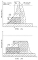
- Figures 3a and 3b illustrate an example of using the power management application 38 to prevent the multiprocessor system 10 from exceeding an average power dissipation limit.
- the DSP 14, DMA 16 and MPU 12 are concurrently running a number of tasks.
- the average power dissipation of the three embedded systems exceeds the average limit imposed on the multiprocessor system 10.
- Figure 3b illustrates a scenario where the same tasks are executed; however, an MPU task is delayed until after the DMA and DSP tasks are completed in order to maintain an acceptable average power dissipation profile.
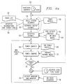
- Figure 4a illustrates a flow chart describing operation of a first embodiment of the power management tasks 38.
- the power management tasks are invoked by the global scheduler 40, which could be executed on the MPU 12 or one of the DSPs 14; the scheduler evaluate the upcoming application and splits it into tasks with associated precedence and exclusion rules.
- the task list 52 could include, for example, audio/video decoding, display control, keyboard control, character recognition, and so on.
- the task list 52 is evaluated in view of the task model file 56 and the accepted degradations file 58.
- the task model file 56 is part of the profiles 36 of the distributed applications layer 32.
- the task model file 56 is a previously generated file that assigns different models to each task in the task list.
- Each model is a collection of data, which could be derived experimentally or by computer aided software design techniques, which defines characteristics of the associated task, such as latency constraints, priority, data flows, initial energy estimate at a reference processor speed, impacts of degradations, and an execution profile on a given processor as a function of MIPs and time.
- the degradation list 58 sets forth the variety of degradations that can be used in generating the scenario.
- a scenario is built.
- the scenario allocates the various tasks to the modules and provides priority information setting the priority with which tasks are executed.
- a scenario energy estimate 59 at a reference speed can be computed from the tasks' energy estimate. If necessary or desirable, tasks may be degraded; i.e., a mode of the task that uses fewer resources may be substituted for the full version of a task. From this scenario, an activities estimate is generated in block 60.
- the activities estimate uses task activity profiles 62 (from the profiling data 36 of the distributed application layer 32) and a hardware architectural model 64 (also from the profiling data 36 of the distributed application layer 32) to generate probabilistic values for hardware activities that will result from the scenario.
- the probabilistic values include each module's wait/run time share (effective MHz), accesses to caches and memories, I/O toggling rates and DMA flow requests and data volume.
- T wait/run time share
- I/O toggling rates and DMA flow requests and data volume.
- the scenario is rejected in decision block 74. In this case, a new scenario is built in block 54 and steps 60, 66 and 70 are repeated. Otherwise, the scenario is used to execute the task list.
- the OS and RTOSs track activities by their respective modules in block 76 using counters 78 incorporated in the hardware.
- the actual activity in the modules of the multiprocessor system 10 may vary from the activities estimated in block 60.
- the data from the hardware counters are monitored on a T periodic basis to produce measured activity values. These measured activity values are used in block 66 to compute an energy value for this period, and hence, an average power value in block 66, as described above, and are compared to the package thermal model in block 72. If the measured values exceed thresholds, then a new scenario is built in block 54.
- the scenarios can be modified dynamically to stay within predefined limits or to adjust to changing environmental conditions.
- Total energy consumption over T for the chip is calculated as: where, f is the frequency, V dd is the supply voltage and ⁇ is the probabilistic (or measured, see discussion in connection with block 76 of this figure) activity.
- ⁇ T ( ⁇ ) *Cpd*f*V 2 / dd is the energy corresponding to a particular hardware module characterized by equivalent dissipation capacitance Cpd ; counters values give ⁇ T ( ⁇ ) and E is the sum of all energies for all modules in the multiprocessor system 10 dissipated within T.
- Average system power dissipation W E/T.
- measured and probabilistic energy consumption is calculated and the average power dissipation is derived from the energy consumption over period T. In most cases, energy consumption information will be more readily available. However, it would also be possible to calculate the power dissipation from measured and probabilistic power consumption.
- Figure 4b is a flow chart describing operation of a second embodiment of the power management tasks 38.
- the flow of Figure 4b is the same as that of Figure 41, except when the scenario construction algorithm is invoked (new task, task delete, real time event) in step 50, instead of choosing one new scenario, n different scenarios that match the performances constraints can be pre-computed in advance and stored in steps 54 and 59, in order to reduce the number of operations within the dynamic loop and provide faster adaptation if the power computed in the tracking loop leads to current scenario rejection in block 74.
- the scenario is rejected, another pre-computed scenario is selected in block 65. Otherwise the operation is the same as shown in Figure 4a.
- FIGS 5 - 8 illustrate the operation of various blocks of Figure 3 in greater detail.
- the build system block 54 is shown in Figure 5.
- a task list 52 In this block, a task list 52, a task model 56, and a list of possible task degradations 58 are used to generate a scenario.
- the task list is dependent upon which tasks are to be executed on the multiprocessor system 10.
- three tasks are shown: MPEG4 decode, wireless modem data receive and keyboard event monitor.
- the tasks could come from any number of sources.
- the task model sets forth conditions which must be taken in consideration in defining the scenario, such as latency and priority constraints, data flow, initial energy estimates, and the impact of degradations. Other conditions could also be used in this block.
- the output of the build system scenario block is a scenario 80, which associates the various tasks with the modules and assigns priorities to each of the tasks.
- the MPEG4 decode task has a priority of 16 and the wireless modem task has a priority of 4.
- the scenarios built in block 54 could be based on a number of different considerations. For example, the scenarios could be built based on providing the maximum performance within the packages thermal constraints. Alternatively, the scenarios could be based on using the lowest possible energy. The optimum scenario could change during operation of a device; for example, with fully charged batteries a device may operate at a maximum performance level. As the power in the batteries diminished below a preset level, the device could operate at the lowest possible power level to sustain operation.
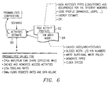
- the scenario 80 from block 54 is used by the activities estimate block 60, shown in Figure 6.
- This block performs a probabilities computation for various parameters that affect power usage in the multiprocessor system 10.
- the probabilistic activities estimate is generated in conjunction with task activity profiles 62 and hardware architectural models 64.
- the task activity profiles include information on the data access types (load/store) and occurrences for the different memories, code profiles, such as the branches and loops used in the task, and the cycles per instruction for instructions in the task.
- the hardware architectural model 64 describes in some way the impact of the task activity profiles 62 on the system latencies, that will permit computation of estimated hardware activities (such as processor run/wait time share).
- This model takes into account the characteristics of the hardware on which the task will be implemented, for example, the sizes of the caches, the width of various buses, the number of I/O pins, whether the cache is write-through or write back, the types of memories used (dynamic, static, flash, and so on) and the clock speeds used in the module.
- the model can consist of a family of curves that represent MPU and DSP effective frequency variations with different parameters, such as data cacheable/non-cacheable, read/write access shares, number of cycles per instruction, and so on.
- values for the effective frequency of each module, the number of memory accesses, the I/O toggling rates and the DMA flow are calculated. Other factors that affect power could also be calculated.
- the power compute block 66 is shown in Figure 8.
- the probabilistic activities from block 60 or the measured activities from block 76 are used to compute various energy values and, hence, power values over a period T.
- the power values are computed in association with hardware power profiles, which are specific to the hardware design of the multiprocessor system 10.
- the hardware profiles could include a Cpd for each module, logic design style (D-type flip-flop, latches, gated clocks and so on), supply voltages and capacitive loads on the outputs. Power computations can be made for integrated modules, and also for external memory or other external devices.
- Activity measure and monitor block 76 is shown in Figure 8. Counters are implemented throughout the multiprocessor system 10 to measure activities on the various modules, such as cache misses, TLB (translation lookaside buffer) misses, non-cacheable memory accesses, wait time, read/write requests for different resources, memory overhead and temperature.
- the activity measure and monitor block 76 outputs values for the effective frequency of each module, the number of memory accesses, the I/O toggling rates and the DMA flow. In a particular implementation, other values may also be measured. The output of this block is sent to the power compute block 66.
- FIG 9 illustrates and example of a multiprocessor system 10 using power/energy management software.
- the multiprocessor system 10 includes a MPU 12, executing an OS, and two DSPs 14 (individually referenced as DSP1 14a and DSP2 14b), each executing a respective RTOS.
- Each module is executing a monitor task 82, which monitors the values in various activity counters 78 throughout the multiprocessor system 10.
- the power compute task is executed on DSP 14a.
- the various monitor tasks retrieve data from associated activity counters 78 and pass the information to DSP 14a to calculate a power value based on measured activities.
- the power management tasks such as power compute task 84 and monitor task 82, can be executed along with other application tasks.
- the power management tasks 38 and profiles 36 are implemented as JAVA class packages in a JAVA real-time environment.
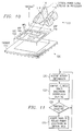
- Figure 10 illustrates an exploded view of a processing device 100, of the type shown in Figure 9, with the layout of various components displayed on a semiconductor die 102.
- the boundaries of components MPU 12, DSP1 14a and DSP2 14b are shown on Figure 10 on die 102.
- Die 102 would be mounted within packaging 110.
- Above die 102 an example of a power dissipation profile 112 that could occur during operation of the processing device 100 is shown.
- the power dissipation profile 112 shows peaks, 114, 116 and 118, which are associated with the operation of respective components. As can be seen from this Figure, power dissipation peak 114 exceeds a predetermined safe range.
- the power dissipation profile 102 can be computed from the events detected by various counters 78 associated with the components as shown in Figure 9.
- a temperature field for the die may be computer from the dissipated power profile.
- a critical power surge such as the one shown at peak 114
- a rescheduling of tasks may be computed by the power computing task 84.
- several solutions may be available to bring peak 114 down to an acceptable level. First, if the task running on MPU 12 was a high priority task, it might be possible to reschedule lower priority tasks on DSP1 14a or DSP2 14b.
- DSP1 14a and DSP2 14b Since the power dissipation in the areas designated by DSP1 14a and DSP2 14b contribute to the power dissipation in the area designated by MPU 12, rescheduling one or more of the tasks using DSP1 14a or DSP2 14b may reduce the peak. Alternatively, it may be possible to reduce the power dissipation shown at peak 114 by reducing the frequency of the MPU 12, DSP1 14a and DSP2 14b.
- Counters 78 can measure activity in many areas of the die 102. For example, for MPU 12, a first counter could measure activity of the instruction cache, a second counter could measure activity of the data cache and a third counter could measure activity of the MAC (multiplier accumulator).
- the counters 78 need not be physically located in the area of the circuit whose activity is being measured. It would also be possible for a single counter to measure activity that affects multiple areas of the die 100.
- Thresholds can be set to identify dangerous situations.
- FIG 11 illustrates a flow chart describing operation of scheduling events to avoid critical temperature effects in a specific area of a die.
- power management software receives activity information. This information is used to compute a power dissipation distribution over the semiconductor die 102 in step 122. The power dissipation distribution is analyzed in step 124. If a threshold is exceeded in any area of the semiconductor die 102, the tasks are adjusted in step 126 to reduce the power dissipation in that area.
- the power dissipation distribution is estimated using activity measurements, it would be possible to measure temperatures directly at various points on the semiconductor and schedule tasks based on actual temperature measurements. For example, the temperature could be estimated by a measured change of an I-V characteristic of a PN junction.
- the counter 78 may be used to derive information necessary to profile tasks for area-specific temperatures, in order to create schedules that avoid critical temperatures in any area of the die 102 during the execution of the tasks. This could be performed as shown in Figures 4a and 4b, with the thresholds be applied to various areas of the device 100.
- This aspect of the present invention provides significant advantages over the prior art. First, it provides for a fully dynamic power management based on the temperature, or estimated temperature, of various areas of a device. As the tasks executed in the device 100 change, the power management can build new scenarios to ensure that temperature thresholds are not exceeded in any area of the device.
- the power management software is transparent to the various tasks that it controls. Thus, even if a particular task does not provide for any power management, the power management software assumes responsibility for executing the task in a manner that is consistent with the power capabilities of the device 100.
- Figure 11 illustrates an embodiment of the invention that accurately measures energy information regarding the operation of a specific task. By increasing the accuracy of the energy information associated with a task, the probability of success for a proposed global scenario is similarly increased.
- FIG 11 provides a more detailed block diagram of MPU 12.
- An MPU core 130 includes a TaskID register 132 and a compare circuit 134.
- Core 130 is coupled to instruction cache 20a and data cache 20b.
- Counters 78 monitor activity within the core.
- Counters 78 have enable ports (En) coupled to the output of compare circuit 134.
- Each processor that may independently execute a task i.e, "autonomous" processors such as an MPU or DSP, but generally not a co-processor or a DMA physical channel
- the device shown in Figure 9 might have three TaskID registers 132 corresponding to the MPU 12, DSP1 14a and DSP2 14b.
- each task being executed by the processing system 10 has a unique identification tag, the Task ID.
- the Task ID is stored in the TaskID register 132.
- the Task ID of the specific task is loaded into comparator 134 (the Task ID of the task being monitored may be stored within comparator 134 or in a register or other memory).
- Comparator 134 outputs a first logical signal (for example, a logical "1") when the identifier in the TaskID register matches the Task ID loaded into comparator 134.
- comparator 134 outputs a second logical signal (for example, a logical "0") when the identifier in the TaskID register is different from the Task ID loaded into comparator 134.
- the output of the comparator 134 is coupled to enable ports of the various counters on the device 10.
- the counters are enabled to measure activity associated with the task.
- the counters are disabled, such that activities associated with other tasks are not measured.
- Some hardware systems are shared between multiple processors. Therefore, in order to accurately measure activity on these shared systems attributable to a distinct task, multiple counters can be coupled to respective compare circuits 134.
- the counter on the shared hardware system could have a Task ID register and comparator to allow counting only when a certain task was active.
- This embodiment can be used for generating energy information for task profiles.
- the energy information can be gathered in an "off-line” mode, where the device 10 is being operated for the purpose of gathering the energy information, or in an "on-line” mode, where the information is gathered during actual operation of the device 10, and the task profiles 36 are updated dynamically during the operation of the device to improve scheduling as tasks are created and terminated.
- a breakpoint could be set when an activity counter reaches a certain value for a given task.
- the Task ID of the current task is stored in the TaskID register 132.
- a processor switches between each current task, giving the appearance that all of the current tasks are being executed simultaneously.
- the active task various state information will be restored to the processor.
- the Task ID associated with the active task is stored in the TaskID register 132 as the state information for the task is restored.
- the counters 78 will be enabled to accumulate activity information.
- the processor switches to a different task, the counters will ignore activity.
- accurate information regarding activity associated with a task during multitasking operations can be obtained.
- the embodiment shown in Figure 12 can be used in conjunction with the embodiment shown in Figures 10 and 11 to obtain area-specific temperate data, if desired.
- This aspect of the invention provides for more accurate profile data that may be used for scheduling tasks. By providing better energy information, the success rate of computing global scenarios, as discussed in connection with Figures 4a and 4b.
- FIG. 13 illustrates an implementation of a mobile communications device 150 with microphone 152, speaker 154, keypad 156, display 158 and antenna 140.
- Internal processing circuitry 162 includes one or more processing devices with the energy saving features described herein. It is contemplated, of course, that many other types of communications systems and computer systems may also benefit from the present invention, particularly those relying on battery power. Examples of such other computer systems include personal digital assistants (PDAS), portable computers, personal digital assistants (PDAs), smart phones, web phones, and the like. As power dissipation is also of concern in desktop and line-powered computer systems and micro-controller applications, particularly from a reliability standpoint, it is also contemplated that the present invention may also provide benefits to such line-powered systems.
- PDAS personal digital assistants
- PDAs personal digital assistants
- the present invention may also provide benefits to such line-powered systems.
- Telecommunications device 150 includes microphone 152 for receiving audio input, and speaker 154 for outputting audible output, in the conventional manner.
- Microphone 152 and speaker 154 are connected to processing circuitry 162 which receives and transmits audio and data signals.
Landscapes
- Engineering & Computer Science (AREA)
- Theoretical Computer Science (AREA)
- Physics & Mathematics (AREA)
- General Engineering & Computer Science (AREA)
- General Physics & Mathematics (AREA)
- Software Systems (AREA)
- Human Computer Interaction (AREA)
- Quality & Reliability (AREA)
- Power Sources (AREA)
Abstract
Description

Claims (15)
- A method for controlling the execution of multiple tasks in a processing circuit including several modules, comprising the steps of:determining temperature-associated information at various areas of the processing circuit; andexecuting the tasks on said plurality of processing modules responsive to said temperature-associated information to prevent problems associated with one or more areas exceeding a temperature threshold.
- The method of claim 1 wherein said determining step comprises the step of monitoring operations executed by said modules.
- The method of claim 1 wherein said determining step comprises the step of calculating power dissipation information at various locations in said processing circuit.
- The method of claim 1 wherein said determining step comprises the step of calculating a current temperature at various locations in said processing circuit.
- The method of claim 1 wherein said determining step comprises the steps of:generating a task allocation scenario;estimating temperature-associated information for various locations in the processing circuit;computing the temperature associated with said activities.
- The method of claim 5 wherein said step of generating a task allocation scenario comprises the step of receiving a task list describing the tasks to be executed and a task model describing the tasks.
- The method of claim 6 wherein the task model includes initial area-specific power dissipation estimates for each task.
- A processing circuit including a plurality of processing modules for executing multiple tasks comprising:circuitry for determining temperature-associated information at various areas of the processing circuit; andcircuitry for executing the tasks on said plurality of processing modules responsive to said temperature-associated information to prevent problems associated with one or more areas exceeding a temperature threshold.
- The processing circuit of claim 8 wherein said determining circuitry comprises circuitry for monitoring operations executed by said processing modules.
- The processing circuit of claim 8 wherein said determining circuitry comprises circuitry for calculating power dissipation information at various locations in said processing circuit.
- The processing circuit of claim 8 wherein said determining circuitry comprises circuitry for calculating a current temperature at various locations in said processing circuit.
- The processing circuit of claim 8 wherein said determining circuitry comprises circuitry for generating a task allocation scenario, estimating temperature-associated information for various locations in the processing circuit and computing the temperature associated with said activities.
- The processing circuit of claim 12 wherein said circuitry for generating a task allocation scenario comprises circuitry for receiving a task list describing the tasks to be executed and a task model describing the tasks.
- The processing circuit of claim 13 wherein the task model includes initial area-specific power dissipation estimates for each task.
- A mobile communications device comprising:an antenna for receiving and transmitting signals; andreceiver/transmitter circuitry coupled to said antenna for sending and receiving audio and data signals, said receiver/transmitter circuitry including a processing circuit comprising:circuitry for determining temperature-associated information at various areas of the processing circuit; andcircuitry for executing the tasks on said plurality of processing modules responsive to said temperature-associated information to prevent problems associated with one or more areas exceeding a temperature threshold.
Priority Applications (3)
| Application Number | Priority Date | Filing Date | Title |
|---|---|---|---|
| EP00402948A EP1182538B1 (en) | 2000-08-21 | 2000-10-24 | Temperature field controlled scheduling for processing systems |
| US09/932,361 US7174194B2 (en) | 2000-10-24 | 2001-08-17 | Temperature field controlled scheduling for processing systems |
| JP2001325363A JP4039843B2 (en) | 2000-10-24 | 2001-10-23 | Method and processing circuit for controlling execution of multiple tasks |
Applications Claiming Priority (3)
| Application Number | Priority Date | Filing Date | Title |
|---|---|---|---|
| EP00402331A EP1182559B1 (en) | 2000-08-21 | 2000-08-21 | Improved microprocessor |
| EP00402331 | 2000-08-21 | ||
| EP00402948A EP1182538B1 (en) | 2000-08-21 | 2000-10-24 | Temperature field controlled scheduling for processing systems |
Publications (3)
| Publication Number | Publication Date |
|---|---|
| EP1182538A2 true EP1182538A2 (en) | 2002-02-27 |
| EP1182538A3 EP1182538A3 (en) | 2003-10-15 |
| EP1182538B1 EP1182538B1 (en) | 2010-04-07 |
Family
ID=26073545
Family Applications (1)
| Application Number | Title | Priority Date | Filing Date |
|---|---|---|---|
| EP00402948A Expired - Lifetime EP1182538B1 (en) | 2000-08-21 | 2000-10-24 | Temperature field controlled scheduling for processing systems |
Country Status (1)
| Country | Link |
|---|---|
| EP (1) | EP1182538B1 (en) |
Cited By (26)
| Publication number | Priority date | Publication date | Assignee | Title |
|---|---|---|---|---|
| EP1365312A1 (en) * | 2002-05-20 | 2003-11-26 | Texas Instruments Incorporated | Energy-aware scheduling of application execution |
| GB2406677A (en) * | 2003-10-03 | 2005-04-06 | Hewlett Packard Development Co | Managing power consumption and thermal load of rack-mounted processing equipment |
| US7120715B2 (en) * | 2000-08-21 | 2006-10-10 | Texas Instruments Incorporated | Priority arbitration based on current task and MMU |
| US7146511B2 (en) | 2003-10-07 | 2006-12-05 | Hewlett-Packard Development Company, L.P. | Rack equipment application performance modification system and method |
| WO2007062984A3 (en) * | 2005-11-29 | 2007-07-12 | Ibm | Software thermal profile generation |
| US7376532B2 (en) | 2005-11-29 | 2008-05-20 | International Business Machines Corporation | Maximal temperature logging |
| US7386414B2 (en) | 2005-11-29 | 2008-06-10 | International Business Machines Corporation | Generation of hardware thermal profiles for a set of processors |
| US7395174B2 (en) | 2005-11-29 | 2008-07-01 | International Business Machines Corporation | Generation of software thermal profiles executed on a set of processors using thermal sampling |
| CN100422942C (en) * | 2004-11-04 | 2008-10-01 | 株式会社东芝 | Processor system with temperature sensor and control method thereof |
| US7460932B2 (en) | 2005-11-29 | 2008-12-02 | International Business Machines Corporation | Support of deep power savings mode and partial good in a thermal management system |
| US7480586B2 (en) | 2005-11-29 | 2009-01-20 | International Business Machines Corporation | Thermal interrupt generation |
| US7490017B2 (en) | 2005-11-29 | 2009-02-10 | International Business Machines Corporation | Analytical generation of software thermal profiles |
| US7512513B2 (en) | 2005-11-29 | 2009-03-31 | International Business Machines Corporation | Thermal throttling control for testing of real-time software |
| US7512530B2 (en) | 2005-11-29 | 2009-03-31 | International Business Machines Corporation | Generation of software thermal profiles for applications in a simulated environment |
| US7552346B2 (en) | 2006-05-03 | 2009-06-23 | International Business Machines Corporation | Dynamically adapting software for reducing a thermal state of a processor core based on its thermal index |
| US7596430B2 (en) | 2006-05-03 | 2009-09-29 | International Business Machines Corporation | Selection of processor cores for optimal thermal performance |
| US7603576B2 (en) | 2005-11-29 | 2009-10-13 | International Business Machines Corporation | Hysteresis in thermal throttling |
| US7681053B2 (en) | 2005-11-29 | 2010-03-16 | International Business Machines Corporation | Thermal throttle control with minimal impact to interrupt latency |
| US7721128B2 (en) | 2005-11-29 | 2010-05-18 | International Business Machines Corporation | Implementation of thermal throttling logic |
| US7848901B2 (en) | 2005-11-29 | 2010-12-07 | International Business Machines Corporation | Tracing thermal data via performance monitoring |
| US8027798B2 (en) | 2007-11-08 | 2011-09-27 | International Business Machines Corporation | Digital thermal sensor test implementation without using main core voltage supply |
| US8037893B2 (en) | 2006-05-03 | 2011-10-18 | International Business Machines Corporation | Optimizing thermal performance using thermal flow analysis |
| CN103164274A (en) * | 2013-02-18 | 2013-06-19 | 华东师范大学 | Fixed priority real-time task static scheduling method based on temperature constraint |
| US8548393B2 (en) | 2007-03-23 | 2013-10-01 | Fujitsu Limited | Electronic apparatus and storage medium storing load distribution program |
| US9830889B2 (en) | 2009-12-31 | 2017-11-28 | Nvidia Corporation | Methods and system for artifically and dynamically limiting the display resolution of an application |
| EP3959582A4 (en) * | 2019-07-22 | 2022-06-15 | Samsung Electronics Co., Ltd. | ELECTRONIC DEVICE AND METHOD FOR CONTROLLING DATA RATE BASED ON HEAT GENERATION IN AN ELECTRONIC DEVICE |
Families Citing this family (8)
| Publication number | Priority date | Publication date | Assignee | Title |
|---|---|---|---|---|
| US7849332B1 (en) | 2002-11-14 | 2010-12-07 | Nvidia Corporation | Processor voltage adjustment system and method |
| US7886164B1 (en) | 2002-11-14 | 2011-02-08 | Nvidia Corporation | Processor temperature adjustment system and method |
| US7882369B1 (en) | 2002-11-14 | 2011-02-01 | Nvidia Corporation | Processor performance adjustment system and method |
| US9134782B2 (en) | 2007-05-07 | 2015-09-15 | Nvidia Corporation | Maintaining optimum voltage supply to match performance of an integrated circuit |
| US8370663B2 (en) | 2008-02-11 | 2013-02-05 | Nvidia Corporation | Power management with dynamic frequency adjustments |
| US8477499B2 (en) | 2009-06-05 | 2013-07-02 | Laird Technologies, Inc. | Assemblies and methods for dissipating heat from handheld electronic devices |
| US9256265B2 (en) | 2009-12-30 | 2016-02-09 | Nvidia Corporation | Method and system for artificially and dynamically limiting the framerate of a graphics processing unit |
| US8839006B2 (en) | 2010-05-28 | 2014-09-16 | Nvidia Corporation | Power consumption reduction systems and methods |
Family Cites Families (3)
| Publication number | Priority date | Publication date | Assignee | Title |
|---|---|---|---|---|
| US5339445A (en) * | 1992-11-16 | 1994-08-16 | Harris Corporation | Method of autonomously reducing power consumption in a computer sytem by compiling a history of power consumption |
| DE69532596T2 (en) * | 1994-05-09 | 2004-08-05 | Canon K.K. | Method for controlling the power supply in a multi-process operating environment |
| CN1159021A (en) * | 1996-03-06 | 1997-09-10 | 三菱电机株式会社 | System clock setting device |
-
2000
- 2000-10-24 EP EP00402948A patent/EP1182538B1/en not_active Expired - Lifetime
Cited By (40)
| Publication number | Priority date | Publication date | Assignee | Title |
|---|---|---|---|---|
| US7120715B2 (en) * | 2000-08-21 | 2006-10-10 | Texas Instruments Incorporated | Priority arbitration based on current task and MMU |
| EP1365312A1 (en) * | 2002-05-20 | 2003-11-26 | Texas Instruments Incorporated | Energy-aware scheduling of application execution |
| US8032891B2 (en) | 2002-05-20 | 2011-10-04 | Texas Instruments Incorporated | Energy-aware scheduling of application execution |
| GB2406677A (en) * | 2003-10-03 | 2005-04-06 | Hewlett Packard Development Co | Managing power consumption and thermal load of rack-mounted processing equipment |
| GB2406677B (en) * | 2003-10-03 | 2007-06-06 | Hewlett Packard Development Co | A rack equipment management system and method |
| US7363516B2 (en) | 2003-10-03 | 2008-04-22 | Hewlett-Packard Development Company, L.P. | Rack equipment management system and method |
| US7146511B2 (en) | 2003-10-07 | 2006-12-05 | Hewlett-Packard Development Company, L.P. | Rack equipment application performance modification system and method |
| CN100422942C (en) * | 2004-11-04 | 2008-10-01 | 株式会社东芝 | Processor system with temperature sensor and control method thereof |
| US7756666B2 (en) | 2005-11-29 | 2010-07-13 | International Business Machines Corporation | Generation of hardware thermal profiles for a set of processors |
| US7756668B2 (en) | 2005-11-29 | 2010-07-13 | International Business Machines Corporation | Maximal temperature logging |
| US7376532B2 (en) | 2005-11-29 | 2008-05-20 | International Business Machines Corporation | Maximal temperature logging |
| US7460932B2 (en) | 2005-11-29 | 2008-12-02 | International Business Machines Corporation | Support of deep power savings mode and partial good in a thermal management system |
| US7480586B2 (en) | 2005-11-29 | 2009-01-20 | International Business Machines Corporation | Thermal interrupt generation |
| US7480585B2 (en) | 2005-11-29 | 2009-01-20 | International Business Machines Corporation | Tracing thermal data via performance monitoring |
| US7490017B2 (en) | 2005-11-29 | 2009-02-10 | International Business Machines Corporation | Analytical generation of software thermal profiles |
| US7512513B2 (en) | 2005-11-29 | 2009-03-31 | International Business Machines Corporation | Thermal throttling control for testing of real-time software |
| US7386414B2 (en) | 2005-11-29 | 2008-06-10 | International Business Machines Corporation | Generation of hardware thermal profiles for a set of processors |
| US9097590B2 (en) | 2005-11-29 | 2015-08-04 | International Business Machines Corporation | Tracing thermal data via performance monitoring |
| WO2007062984A3 (en) * | 2005-11-29 | 2007-07-12 | Ibm | Software thermal profile generation |
| US7603576B2 (en) | 2005-11-29 | 2009-10-13 | International Business Machines Corporation | Hysteresis in thermal throttling |
| US7681053B2 (en) | 2005-11-29 | 2010-03-16 | International Business Machines Corporation | Thermal throttle control with minimal impact to interrupt latency |
| US7698089B2 (en) | 2005-11-29 | 2010-04-13 | International Business Machines Corporation | Generation of software thermal profiles executed on a set of processors using processor activity |
| US7395174B2 (en) | 2005-11-29 | 2008-07-01 | International Business Machines Corporation | Generation of software thermal profiles executed on a set of processors using thermal sampling |
| US7721128B2 (en) | 2005-11-29 | 2010-05-18 | International Business Machines Corporation | Implementation of thermal throttling logic |
| US7512530B2 (en) | 2005-11-29 | 2009-03-31 | International Business Machines Corporation | Generation of software thermal profiles for applications in a simulated environment |
| US7747407B2 (en) | 2005-11-29 | 2010-06-29 | International Business Machines Corporation | Thermal interrupt generation |
| CN1975628B (en) * | 2005-11-29 | 2010-07-21 | 国际商业机器公司 | Method and system for generating hardware thermal distribution of a set of processors |
| US7848901B2 (en) | 2005-11-29 | 2010-12-07 | International Business Machines Corporation | Tracing thermal data via performance monitoring |
| US7957848B2 (en) | 2005-11-29 | 2011-06-07 | International Business Machines Corporation | Support of deep power savings mode and partial good in a thermal management system |
| US7596430B2 (en) | 2006-05-03 | 2009-09-29 | International Business Machines Corporation | Selection of processor cores for optimal thermal performance |
| US8037893B2 (en) | 2006-05-03 | 2011-10-18 | International Business Machines Corporation | Optimizing thermal performance using thermal flow analysis |
| US7552346B2 (en) | 2006-05-03 | 2009-06-23 | International Business Machines Corporation | Dynamically adapting software for reducing a thermal state of a processor core based on its thermal index |
| US8548393B2 (en) | 2007-03-23 | 2013-10-01 | Fujitsu Limited | Electronic apparatus and storage medium storing load distribution program |
| US8027798B2 (en) | 2007-11-08 | 2011-09-27 | International Business Machines Corporation | Digital thermal sensor test implementation without using main core voltage supply |
| US9830889B2 (en) | 2009-12-31 | 2017-11-28 | Nvidia Corporation | Methods and system for artifically and dynamically limiting the display resolution of an application |
| CN103164274A (en) * | 2013-02-18 | 2013-06-19 | 华东师范大学 | Fixed priority real-time task static scheduling method based on temperature constraint |
| CN103164274B (en) * | 2013-02-18 | 2016-06-01 | 华东师范大学 | The static scheduling method of the real-time task of a kind of fixing priority based on temperature restraint |
| EP3959582A4 (en) * | 2019-07-22 | 2022-06-15 | Samsung Electronics Co., Ltd. | ELECTRONIC DEVICE AND METHOD FOR CONTROLLING DATA RATE BASED ON HEAT GENERATION IN AN ELECTRONIC DEVICE |
| US11977931B2 (en) | 2019-07-22 | 2024-05-07 | Samsung Electronics Co., Ltd. | Electronic device and method for controlling data throughput based on heat generation in electronic device |
| US20240231955A1 (en) * | 2019-07-22 | 2024-07-11 | Samsung Electronics Co., Ltd. | Electronic device and method for controlling data throughput based on heat generation in electronic device |
Also Published As
| Publication number | Publication date |
|---|---|
| EP1182538A3 (en) | 2003-10-15 |
| EP1182538B1 (en) | 2010-04-07 |
Similar Documents
| Publication | Publication Date | Title |
|---|---|---|
| US7174194B2 (en) | Temperature field controlled scheduling for processing systems | |
| EP1182556B1 (en) | Task based adaptive profiling and debugging | |
| EP1182538B1 (en) | Temperature field controlled scheduling for processing systems | |
| EP1096360B1 (en) | Intelligent power management for distributed processing systems | |
| US6901521B2 (en) | Dynamic hardware control for energy management systems using task attributes | |
| US6889330B2 (en) | Dynamic hardware configuration for energy management systems using task attributes | |
| US7346787B2 (en) | System and method for adaptive power management | |
| US7770034B2 (en) | Performance monitoring based dynamic voltage and frequency scaling | |
| US7814485B2 (en) | System and method for adaptive power management based on processor utilization and cache misses | |
| US6769052B2 (en) | Cache with selective write allocation | |
| CN104583900B (en) | Dynamically switch workloads between heterogeneous cores of a processor | |
| US20160378168A1 (en) | Dynamic power management optimization | |
| US20140344599A1 (en) | Method and System for Power Management | |
| CN104778112B (en) | The system and method for adaptive voltage frequency adjustment | |
| Mittal et al. | Master: A multicore cache energy-saving technique using dynamic cache reconfiguration | |
| US20130080803A1 (en) | Estimating Temperature Of A Processor Core In A Low Power State | |
| Paul | Real-time power management for embedded M2M using intelligent learning methods | |
| Sartor et al. | HiLITE: Hierarchical and lightweight imitation learning for power management of embedded SoCs | |
| US10275007B2 (en) | Performance management for a multiple-CPU platform | |
| KR20240025227A (en) | Processor for performing dynamic voltage and frequency scaling, electronic device having the same, and operating method thereof | |
| KR100830747B1 (en) | Intelligent power management for distributed processing systems | |
| Zhong et al. | Frequency-aware energy optimization for real-time periodic and aperiodic tasks | |
| US9766672B2 (en) | System for managing power provided to a processor or memory based on a measured memory consumption characteristic | |
| KR20240088453A (en) | A system on chip and method of operation thereof | |
| Mercati et al. | Blast: Battery lifetime-constrained adaptation with selected target in mobile devices |
Legal Events
| Date | Code | Title | Description |
|---|---|---|---|
| PUAI | Public reference made under article 153(3) epc to a published international application that has entered the european phase |
Free format text: ORIGINAL CODE: 0009012 |
|
| AK | Designated contracting states |
Kind code of ref document: A2 Designated state(s): AT BE CH CY DE DK ES FI FR GB GR IE IT LI LU MC NL PT SE |
|
| AX | Request for extension of the european patent |
Free format text: AL;LT;LV;MK;RO;SI |
|
| PUAL | Search report despatched |
Free format text: ORIGINAL CODE: 0009013 |
|
| AK | Designated contracting states |
Kind code of ref document: A3 Designated state(s): AT BE CH CY DE DK ES FI FR GB GR IE IT LI LU MC NL PT SE |
|
| AX | Request for extension of the european patent |
Extension state: AL LT LV MK RO SI |
|
| RIC1 | Information provided on ipc code assigned before grant |
Ipc: 7G 06F 11/34 A Ipc: 7G 06F 1/20 B Ipc: 7G 06F 9/46 B |
|
| 17P | Request for examination filed |
Effective date: 20040224 |
|
| RAP1 | Party data changed (applicant data changed or rights of an application transferred) |
Owner name: TEXAS INSTRUMENTS FRANCE Owner name: TEXAS INSTRUMENTS INCORPORATED |
|
| AKX | Designation fees paid |
Designated state(s): AT BE CH CY DE DK ES FI FR GB GR IE IT LI LU MC NL PT SE |
|
| 17Q | First examination report despatched |
Effective date: 20050607 |
|
| GRAP | Despatch of communication of intention to grant a patent |
Free format text: ORIGINAL CODE: EPIDOSNIGR1 |
|
| GRAS | Grant fee paid |
Free format text: ORIGINAL CODE: EPIDOSNIGR3 |
|
| GRAA | (expected) grant |
Free format text: ORIGINAL CODE: 0009210 |
|
| AK | Designated contracting states |
Kind code of ref document: B1 Designated state(s): AT BE CH CY DE DK ES FI FR GB GR IE IT LI LU MC NL PT SE |
|
| REG | Reference to a national code |
Ref country code: GB Ref legal event code: FG4D |
|
| REG | Reference to a national code |
Ref country code: CH Ref legal event code: EP |
|
| REG | Reference to a national code |
Ref country code: IE Ref legal event code: FG4D |
|
| REF | Corresponds to: |
Ref document number: 60044128 Country of ref document: DE Date of ref document: 20100520 Kind code of ref document: P |
|
| REG | Reference to a national code |
Ref country code: NL Ref legal event code: VDEP Effective date: 20100407 |
|
| PG25 | Lapsed in a contracting state [announced via postgrant information from national office to epo] |
Ref country code: ES Free format text: LAPSE BECAUSE OF FAILURE TO SUBMIT A TRANSLATION OF THE DESCRIPTION OR TO PAY THE FEE WITHIN THE PRESCRIBED TIME-LIMIT Effective date: 20100718 Ref country code: SE Free format text: LAPSE BECAUSE OF FAILURE TO SUBMIT A TRANSLATION OF THE DESCRIPTION OR TO PAY THE FEE WITHIN THE PRESCRIBED TIME-LIMIT Effective date: 20100407 Ref country code: NL Free format text: LAPSE BECAUSE OF FAILURE TO SUBMIT A TRANSLATION OF THE DESCRIPTION OR TO PAY THE FEE WITHIN THE PRESCRIBED TIME-LIMIT Effective date: 20100407 |
|
| PG25 | Lapsed in a contracting state [announced via postgrant information from national office to epo] |
Ref country code: FI Free format text: LAPSE BECAUSE OF FAILURE TO SUBMIT A TRANSLATION OF THE DESCRIPTION OR TO PAY THE FEE WITHIN THE PRESCRIBED TIME-LIMIT Effective date: 20100407 Ref country code: AT Free format text: LAPSE BECAUSE OF FAILURE TO SUBMIT A TRANSLATION OF THE DESCRIPTION OR TO PAY THE FEE WITHIN THE PRESCRIBED TIME-LIMIT Effective date: 20100407 |
|
| PG25 | Lapsed in a contracting state [announced via postgrant information from national office to epo] |
Ref country code: GR Free format text: LAPSE BECAUSE OF FAILURE TO SUBMIT A TRANSLATION OF THE DESCRIPTION OR TO PAY THE FEE WITHIN THE PRESCRIBED TIME-LIMIT Effective date: 20100708 Ref country code: CY Free format text: LAPSE BECAUSE OF FAILURE TO SUBMIT A TRANSLATION OF THE DESCRIPTION OR TO PAY THE FEE WITHIN THE PRESCRIBED TIME-LIMIT Effective date: 20100407 |
|
| PG25 | Lapsed in a contracting state [announced via postgrant information from national office to epo] |
Ref country code: PT Free format text: LAPSE BECAUSE OF FAILURE TO SUBMIT A TRANSLATION OF THE DESCRIPTION OR TO PAY THE FEE WITHIN THE PRESCRIBED TIME-LIMIT Effective date: 20100809 Ref country code: DK Free format text: LAPSE BECAUSE OF FAILURE TO SUBMIT A TRANSLATION OF THE DESCRIPTION OR TO PAY THE FEE WITHIN THE PRESCRIBED TIME-LIMIT Effective date: 20100407 |
|
| PLBE | No opposition filed within time limit |
Free format text: ORIGINAL CODE: 0009261 |
|
| STAA | Information on the status of an ep patent application or granted ep patent |
Free format text: STATUS: NO OPPOSITION FILED WITHIN TIME LIMIT |
|
| PG25 | Lapsed in a contracting state [announced via postgrant information from national office to epo] |
Ref country code: BE Free format text: LAPSE BECAUSE OF FAILURE TO SUBMIT A TRANSLATION OF THE DESCRIPTION OR TO PAY THE FEE WITHIN THE PRESCRIBED TIME-LIMIT Effective date: 20100407 |
|
| 26N | No opposition filed |
Effective date: 20110110 |
|
| PG25 | Lapsed in a contracting state [announced via postgrant information from national office to epo] |
Ref country code: IT Free format text: LAPSE BECAUSE OF FAILURE TO SUBMIT A TRANSLATION OF THE DESCRIPTION OR TO PAY THE FEE WITHIN THE PRESCRIBED TIME-LIMIT Effective date: 20100407 |
|
| PG25 | Lapsed in a contracting state [announced via postgrant information from national office to epo] |
Ref country code: MC Free format text: LAPSE BECAUSE OF NON-PAYMENT OF DUE FEES Effective date: 20101031 |
|
| REG | Reference to a national code |
Ref country code: CH Ref legal event code: PL |
|
| PG25 | Lapsed in a contracting state [announced via postgrant information from national office to epo] |
Ref country code: LI Free format text: LAPSE BECAUSE OF NON-PAYMENT OF DUE FEES Effective date: 20101031 Ref country code: CH Free format text: LAPSE BECAUSE OF NON-PAYMENT OF DUE FEES Effective date: 20101031 |
|
| PG25 | Lapsed in a contracting state [announced via postgrant information from national office to epo] |
Ref country code: IE Free format text: LAPSE BECAUSE OF NON-PAYMENT OF DUE FEES Effective date: 20101024 |
|
| PG25 | Lapsed in a contracting state [announced via postgrant information from national office to epo] |
Ref country code: LU Free format text: LAPSE BECAUSE OF NON-PAYMENT OF DUE FEES Effective date: 20101024 |
|
| REG | Reference to a national code |
Ref country code: FR Ref legal event code: PLFP Year of fee payment: 17 |
|
| REG | Reference to a national code |
Ref country code: FR Ref legal event code: PLFP Year of fee payment: 18 |
|
| REG | Reference to a national code |
Ref country code: FR Ref legal event code: PLFP Year of fee payment: 19 |
|
| PGFP | Annual fee paid to national office [announced via postgrant information from national office to epo] |
Ref country code: FR Payment date: 20190924 Year of fee payment: 20 |
|
| PGFP | Annual fee paid to national office [announced via postgrant information from national office to epo] |
Ref country code: GB Payment date: 20190925 Year of fee payment: 20 |
|
| PGFP | Annual fee paid to national office [announced via postgrant information from national office to epo] |
Ref country code: DE Payment date: 20190917 Year of fee payment: 20 |
|
| REG | Reference to a national code |
Ref country code: DE Ref legal event code: R071 Ref document number: 60044128 Country of ref document: DE |
|
| REG | Reference to a national code |
Ref country code: GB Ref legal event code: PE20 Expiry date: 20201023 |
|
| PG25 | Lapsed in a contracting state [announced via postgrant information from national office to epo] |
Ref country code: GB Free format text: LAPSE BECAUSE OF EXPIRATION OF PROTECTION Effective date: 20201023 |