EP1182516A2 - Apparatus for preventing ink in a wet electrophotographic printer from polluting a roller mounted therein - Google Patents
Apparatus for preventing ink in a wet electrophotographic printer from polluting a roller mounted therein Download PDFInfo
- Publication number
- EP1182516A2 EP1182516A2 EP01304637A EP01304637A EP1182516A2 EP 1182516 A2 EP1182516 A2 EP 1182516A2 EP 01304637 A EP01304637 A EP 01304637A EP 01304637 A EP01304637 A EP 01304637A EP 1182516 A2 EP1182516 A2 EP 1182516A2
- Authority
- EP
- European Patent Office
- Prior art keywords
- roller
- ink
- stopper
- stoppers
- recesses
- Prior art date
- Legal status (The legal status is an assumption and is not a legal conclusion. Google has not performed a legal analysis and makes no representation as to the accuracy of the status listed.)
- Withdrawn
Links
Images



Classifications
-
- G—PHYSICS
- G03—PHOTOGRAPHY; CINEMATOGRAPHY; ANALOGOUS TECHNIQUES USING WAVES OTHER THAN OPTICAL WAVES; ELECTROGRAPHY; HOLOGRAPHY
- G03G—ELECTROGRAPHY; ELECTROPHOTOGRAPHY; MAGNETOGRAPHY
- G03G15/00—Apparatus for electrographic processes using a charge pattern
- G03G15/06—Apparatus for electrographic processes using a charge pattern for developing
- G03G15/10—Apparatus for electrographic processes using a charge pattern for developing using a liquid developer
- G03G15/101—Apparatus for electrographic processes using a charge pattern for developing using a liquid developer for wetting the recording material
-
- G—PHYSICS
- G03—PHOTOGRAPHY; CINEMATOGRAPHY; ANALOGOUS TECHNIQUES USING WAVES OTHER THAN OPTICAL WAVES; ELECTROGRAPHY; HOLOGRAPHY
- G03G—ELECTROGRAPHY; ELECTROPHOTOGRAPHY; MAGNETOGRAPHY
- G03G15/00—Apparatus for electrographic processes using a charge pattern
- G03G15/06—Apparatus for electrographic processes using a charge pattern for developing
- G03G15/10—Apparatus for electrographic processes using a charge pattern for developing using a liquid developer
- G03G15/11—Removing excess liquid developer, e.g. by heat
-
- G—PHYSICS
- G03—PHOTOGRAPHY; CINEMATOGRAPHY; ANALOGOUS TECHNIQUES USING WAVES OTHER THAN OPTICAL WAVES; ELECTROGRAPHY; HOLOGRAPHY
- G03G—ELECTROGRAPHY; ELECTROPHOTOGRAPHY; MAGNETOGRAPHY
- G03G21/00—Arrangements not provided for by groups G03G13/00 - G03G19/00, e.g. cleaning, elimination of residual charge
- G03G21/0088—Arrangements not provided for by groups G03G13/00 - G03G19/00, e.g. cleaning, elimination of residual charge removing liquid developer
Definitions
- the present invention relates to a wet electrophotographic printer and, more particularly, to a wet electrophotographic printer capable of preventing peripheral devices such as a photoreceptor belt from being contaminated by ink which flows outwardly at both ends of a plurality of rollers after being used for a development process.
- a wet electrophotographic printer emits a laser beam onto a photoreceptor such as a photoreceptor belt to generate an electrostatic latent image, develops the electrostatic latent image by using a developer liquid which is normally mixed with a toner in a solid state having a predetermined color, and a carrier in a liquid state functioning as a solvent, and produces a desired image on a paper through transcription.
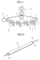
- FIG. 1 there are shown major components of a wet electrophotographic printer as described above.
- a photoreceptor belt 1 is trained over rollers 2, 3, and 4 mounted within a main body of the printer (not shown), to run or circulate therearound.
- An electostatic latent image is formed on the photoreceptor belt 1 by a beam exposing device (not shown), and then is developed by a developing device 10.
- An image formed on the photoreceptor belt 1 by the developing device 10 is dried by a drier 20, up to a level required for transcription, and finally is transcribed in a transcriber 30 onto a paper supplied from the outside.
- the developing device 10 is provided with a plurality of development units (normally four), each of which corresponds to a color.
- development unit 11 includes a development roller 13 for transcribing a developer injected from a developer injection nozzle 12 onto a region of the electrostatic latent image on the photoreceptor belt 1, and a squeegee roller 14 for removing the carrier from the developer transcribed onto the photoreceptor belt 1.
- a cleaning roller for removing sludge of the developer smeared around the squeegee roller 14 is provided in the developing device 10.
- the toner contained in the developer is moved to the region of the electrostatic latent image on the photoreceptor belt 1 to adhere thereto, due to an electric potential difference between the region of the electrostatic latent image and the development roller 13. Since a portion of the photoreceptor belt 1 unexposed to the beam has a higher electric potential than that of the development roller, the developer is smeared on the belt 1 rather than the toner.
- the electrostatic latent image is filmed over with a portion of the toner adhering to the electrostatic latent image by the squeegee roller 14 depressing the photoreceptor belt 1, and the developer with the rest of the toner is removed by the squeegee roller 14.
- the development is performed in such a manner so that the development roller 13 and the squeegee roller 14, both in close contact to the photoreceptor belt 1, depress the photoreceptor belt 1, thereby spreading the developer over the rollers 13, 14. Consequently, the remaining developer not used for the development process is driven or pushed out toward both ends of the rollers 13, 14.
- the rollers 13, 14 may be contaminated with the remaining ink, i.e., the ink pushed out which pollutes the peripheral devices including the photoreceptor belt 1.
- FIGs 2 through 5 a conventional ink contamination prevention device for preventing the contamination by the remaining ink described above is shown.
- the conventional ink contamination prevention device is provided with a pair of protrusions 40, 40' for stopping a flow of the ink toward both ends of the development roller 13.
- the ink contamination prevention device constructed in this manner can prevent the remaining ink 100 from flowing to the outside of the development roller 13, since the protrusions 40, 40' stop the flow of the remaining ink 100.
- the remaining ink may flow from an end of the squeegee roller 14 to the photoreceptor belt 1 to pollute the same, causing a degradation of the quality of the print.
- an aim of the invention to provide an ink pollution prevention device capable of preventing remaining ink from polluting rollers, peripheral devices, and a photoreceptor such as a photoreceptor belt by inhibiting a flow of the remaining ink toward the outside of a roller at both ends of the roller.
- the present invention provides an ink pollution prevention device for use in a wet electrophotographic printer, for preventing a developer from polluting a photoreceptor and peripheral devices by flowing out at the ends of a development roller, a squeegee roller, and a cleaning roller to the outside of the rollers.
- the device is provided with a pair of ink stoppers, with stoppers disposed around both sides of a shaft of each roller in a symmetrical manner with each other.
- Each ink stopper has a plurality of peaks and recesses which form a continuous helical shape in an opposite helical direction from the other ink stopper.
- the helical shape of the ink stopper is oriented so as to permit the ink in the ink stopper to flow toward the center of the roller along the recesses, when the roller is rotated.
- the ink stopper can be integrally formed with a shaft of each roller or independently formed and mounted on the shaft, as a fixed member.
- an apparatus for use in devices in which a liquid is moved to another object by using a cylindrical roller, for preventing a contamination caused by an unwanted movement of the liquid smeared on the roller comprising: a pair of stoppers, wherein each stopper is disposed at one of two sides of the roller, in a symmetrical manner with each other, each stopper having a plurality of peaks and recesses which form a continuous helical shape in an opposite helical direction from the other stopper.
- a pair of stoppers capable of being disposed at one of two sides of a roller, in a symmetrical manner with each other, each stopper having a plurality of peaks and recesses which form a continuous helical shape in an opposite helical direction from the other stopper to permit a liquid in the stopper to flow toward a center of the roller along the recesses when the roller is rotated.
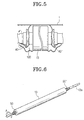
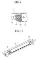
- Figures 6 through 9 show an ink pollution prevention device applied to a development roller according to the present invention.
- Figure 10 shows the ink pollution prevention device applied to a squeegee roller
- Figure 11 shows the ink pollution prevention device applied to a cleaning roller according to the present invention, respectively.
- the ink pollution prevention device comprises a pair of ink stoppers 50, 50', with stoppers formed in a symmetrical manner to each other around a shaft 13a of the development roller 13, which serve to prevent remaining ink not being used in a development process, from flowing out toward the outside of the roller 13 at both ends of the roller 13.
- each of the ink stoppers 50, 50' is formed with a plurality of peaks and recesses which are in a continuous helical form.
- the peak 51 serves to stop the flow of the remaining ink, whereas the recess 52 guides the flow of the remaining ink.
- the helical ink stoppers 50, 50' may be integrally formed on the shaft 13a or formed as a separate member to be mounted on the shaft 13a by a fixing member (not shown). Further, the size or dimension of the ink stoppers 50, 50' is not limited. It is preferable that five through ten peaks should be formed depending upon the construction of the roller.
- a helical direction of the ink stopper 50, 50' is determined by the direction of the rotation of the roller 13. That is, the helical direction is constructed in such a way so that when the roller 13 is rotated, the remaining ink accommodated in the helical recesses flow toward the center of the roller 13 along the recesses.
- Figure 1 is a front side view of the rollers. Since the development roller 13 is rotated in a direction indicated with an arrow A in Figure 6 in this embodiment, the front-sided ink stopper 50 is a right-handed helical, while the rear-sided ink stopper 50' is a left-handed helical.
- a front-sided ink stopper 50 is a right-handed helical, while a rear-sided ink stopper 50' is a left-handed helical.
- the cleaning roller 15 as shown in Figure 11 is rotated in a direction indicated with an arrow D, and thus, the front-sided ink stopper 50' is a left-handed helical, while the rear-sided ink stopper 50 is a right-handed helical.
- the operations of the development roller 13, the squeegee roller 14, and the cleaning roller 15, are basically identical to that of components in a conventional printer.
- the development roller 13 and the squeegee roller 14 retaining the photoreceptor belt 1 are rotated, depressing the photoreceptor belt 1 in a close contact relationship, thereby spreading the developer on a whole surface of the photoreceptor belt 1 to remove the developer remaining outside the region of the electrostatic latent image.
- the remaining ink 100 not being used in the development process is pushed out or moved toward the outside of the rollers 13, 14.
- the helical direction of the ink stoppers 50, 50' is formed to permit the ink to be driven to the center of the rollers when the rollers 13, 14 are rotated, the ink 100 accommodated in the ink stoppers 50, 50' is pushed out toward the center of the rollers 13, 14, in a direction indicated with an arrow B, along the helical recesses, as shown in Figure 9.
- the helical ink stoppers 50, 50' can push out the ink toward the center of the roller 13, even if the remaining ink continues to exist or continues to be supplied. Consequently, since the remaining ink does not flow to the outside of the roller 13, the contamination of the roller 13 by the remaining ink or the contamination of the photoreceptor belt 1 and peripheral devices due to a drop of the ink can be prevented.
- the pair of ink stoppers 50, 50' applied to the cleaning roller 15 as shown in Figure 11, also performs the same function as described above. Consequently, the contamination of the peripheral devices due to the remaining ink flowing toward the outside of the roller 15 can be prevented.
- the present invention has been described with respect to the development roller 13, the squeegee roller 14, and the cleaning roller 15 in this embodiment, rollers which are used in the wet electrophotographic printer, the present invention can be applied to other devices as well, devices in which liquid is moved to another object by using a cylindrical roller, thereby efficiently preventing a contamination caused by unwanted movement of the liquid smeared on the roller.
- the present invention has been described with respect to the photoreceptor belt 1 as an example of a photoreceptor in this embodiment, the present invention can be applied to the wet electrophotographic printer that uses a photoreceptor drum instead of the photoreceptor belt 1.
- the present invention constructed in this manner can stop the flow of the remaining ink at the ends of the development roller 13, the squeegee roller 14, and the cleaning roller 15, by mounting a pair of ink stoppers 50, 50' on the rollers 13, 14, 15. Further, since the helical direction of the ink stopper is formed to permit the ink to be driven toward the center of the roller when the roller is rotated, the ink accommodated in the ink stopper is pushed out toward the center of the roller along the helical recesses. Accordingly, the contamination of the rollers 13, 14, 15 the photoreceptor belt 1, and other peripheral devices, which occurs when the remaining ink flows to the outside of the rollers at both ends of the rollers, can be inherently prevented. As a result, the peripheral device can maintain a proper lifetime and a quality of the print can be enhanced.
Landscapes
- Physics & Mathematics (AREA)
- General Physics & Mathematics (AREA)
- Wet Developing In Electrophotography (AREA)
- Cleaning In Electrography (AREA)
Abstract
Description
Claims (6)
- An ink pollution prevention device for use in a wet electrophotographic printer, for preventing a developer from polluting a photoreceptor and peripheral devices by flowing out at the ends of a development roller, a squeegee roller or a cleaning roller, the device comprising:a pair of ink stoppers (50,50'), wherein each stopper is disposed at one of two sides of a shaft (13a) of the roller (13), in a symmetrical manner with each other, each stopper having a plurality of peaks (51) and recesses (52) which form a continuous helical shape in an opposite helical direction from the other ink stopper.
- The device as claimed in claim 1, wherein the helical direction of the ink stopper (50) is formed to permit the ink in the ink stopper (50) to flow toward the center of the roller along the recesses (52) when the roller (13) is rotated.
- The device as claimed in claim 1 or 2, wherein the ink stoppers (50,50') are integrally formed with the shaft (13a) of the roller (13).
- The device as claimed in claim 1 or 2, wherein the ink stoppers (50,50') are independently formed and mounted on the shaft (13a) of the roller (13).
- An apparatus for use in devices in which a liquid is moved to another object by using a cylindrical roller, for preventing a contamination caused by an unwanted movement of the liquid smeared on the roller, the apparatus comprising:a pair of stoppers (50,50'), wherein each stopper is disposed at one of two sides of the roller (13), in a symmetrical manner with each other, each stopper having a plurality of peaks (51) and recesses (52) which form a continuous helical shape in an opposite helical direction from the other stopper.
- A pair of stoppers (50,50') capable of being disposed at one of two sides of a roller (13), in a symmetrical manner with each other, each stopper (50,50') having a plurality of peaks (51) and recesses (52) which form a continuous helical shape in an opposite helical direction from the other stopper (50,50') to permit a liquid in the stopper to flow toward a center of the roller along the recesses when the roller is rotated.
Applications Claiming Priority (2)
| Application Number | Priority Date | Filing Date | Title |
|---|---|---|---|
| KR1020000049018A KR20020015883A (en) | 2000-08-23 | 2000-08-23 | Apparatus for preventing ink pollution of roller for wet electrophotographic printer |
| KR2000049018 | 2000-08-23 |
Publications (2)
| Publication Number | Publication Date |
|---|---|
| EP1182516A2 true EP1182516A2 (en) | 2002-02-27 |
| EP1182516A3 EP1182516A3 (en) | 2004-09-29 |
Family
ID=19684762
Family Applications (1)
| Application Number | Title | Priority Date | Filing Date |
|---|---|---|---|
| EP01304637A Withdrawn EP1182516A3 (en) | 2000-08-23 | 2001-05-25 | Apparatus for preventing ink in a wet electrophotographic printer from polluting a roller mounted therein |
Country Status (4)
| Country | Link |
|---|---|
| US (1) | US6597880B2 (en) |
| EP (1) | EP1182516A3 (en) |
| JP (1) | JP3520059B2 (en) |
| KR (1) | KR20020015883A (en) |
Families Citing this family (4)
| Publication number | Priority date | Publication date | Assignee | Title |
|---|---|---|---|---|
| US7627264B2 (en) * | 2005-09-30 | 2009-12-01 | Brother Kogyo Kabushiki Kaisha | Developing device and image forming apparatus |
| JP5335546B2 (en) * | 2009-05-12 | 2013-11-06 | キヤノン株式会社 | Image forming apparatus |
| WO2017131701A1 (en) * | 2016-01-28 | 2017-08-03 | Hewlett-Packard Development Company, L.P. | Printing liquid developer |
| CN110178090A (en) | 2017-01-31 | 2019-08-27 | 惠普深蓝有限责任公司 | Roller seals for developer units in liquid electrophotographic printers |
Family Cites Families (7)
| Publication number | Priority date | Publication date | Assignee | Title |
|---|---|---|---|---|
| US1448079A (en) * | 1920-07-08 | 1923-03-13 | Noeggerath Jacob Emil | Viscosity pump |
| JPS57142674A (en) * | 1981-02-27 | 1982-09-03 | Ricoh Co Ltd | Electrophotographic device |
| US4568253A (en) * | 1983-11-29 | 1986-02-04 | Tecumseh Products Company | Horizontal shaft oil pump |
| US4965568A (en) | 1989-03-01 | 1990-10-23 | Atalla Martin M | Multilevel security apparatus and method with personal key |
| US5322298A (en) * | 1992-06-09 | 1994-06-21 | Dresser-Rand Company | Shaft seal |
| JPH08179634A (en) | 1994-12-23 | 1996-07-12 | Ricoh Co Ltd | Wet image forming device |
| CA2233486C (en) * | 1995-10-02 | 2003-06-17 | Thomas W. Ramsay | Rotary seal and/or bearing |
-
2000
- 2000-08-23 KR KR1020000049018A patent/KR20020015883A/en not_active Ceased
-
2001
- 2001-05-04 US US09/848,502 patent/US6597880B2/en not_active Expired - Fee Related
- 2001-05-25 EP EP01304637A patent/EP1182516A3/en not_active Withdrawn
- 2001-06-19 JP JP2001185236A patent/JP3520059B2/en not_active Expired - Fee Related
Also Published As
| Publication number | Publication date |
|---|---|
| KR20020015883A (en) | 2002-03-02 |
| EP1182516A3 (en) | 2004-09-29 |
| US6597880B2 (en) | 2003-07-22 |
| US20020025182A1 (en) | 2002-02-28 |
| JP2002072694A (en) | 2002-03-12 |
| JP3520059B2 (en) | 2004-04-19 |
Similar Documents
| Publication | Publication Date | Title |
|---|---|---|
| US20050206553A1 (en) | Object detection apparatus, object detection method, object detection program, and distance sensor | |
| US7620339B2 (en) | Image forming apparatus including first and second cleaning members | |
| US6611668B2 (en) | Image forming apparatus with residual developing charging feature | |
| US5940661A (en) | Image forming apparatus with a charging member which removes smears on an image forming member | |
| EP1182516A2 (en) | Apparatus for preventing ink in a wet electrophotographic printer from polluting a roller mounted therein | |
| KR100370304B1 (en) | Liquid-developing electro-photographic printer photosensitive body cleaning method | |
| US7013106B2 (en) | Liquid electrophotographic image-forming apparatus having anti-wraparound device for developer removal | |
| US6944416B2 (en) | Image forming apparatus | |
| JP5501077B2 (en) | Image forming apparatus | |
| KR100455323B1 (en) | Charging Device and Image Forming Apparatus | |
| US5832342A (en) | Image forming machine with a contact type developing device | |
| US7120378B2 (en) | Image forming apparatus using a liquid developer in which carrier liquid backflow is inhibited | |
| KR100243237B1 (en) | Development apparatus in electrographic printer | |
| US6243553B1 (en) | Method for cleaning the developer for a liquid electrophotographic printer | |
| KR100252100B1 (en) | Wet type electrophotographic printing device | |
| KR100261094B1 (en) | Transfer roller fringing prevention device of printing press | |
| KR100503057B1 (en) | Developing unit for liquid electrophotographic printing apparatus | |
| KR100428644B1 (en) | Developing apparatus for liquid type printer | |
| KR200259771Y1 (en) | Liquid Carrier Removal Device for Wet Electrophotographic Printers | |
| KR100338752B1 (en) | Electrophotographic printer with paper guide device | |
| KR100335427B1 (en) | Transfer roller cleaning apparatus for printer | |
| KR100346716B1 (en) | Cleanng apparatus for transfer roller of liquid electrophotographic printing device | |
| KR100297757B1 (en) | Developing device of wet electronograph printer | |
| JP2005300875A (en) | Image forming apparatus | |
| JP2009025606A (en) | Image forming apparatus |
Legal Events
| Date | Code | Title | Description |
|---|---|---|---|
| PUAI | Public reference made under article 153(3) epc to a published international application that has entered the european phase |
Free format text: ORIGINAL CODE: 0009012 |
|
| 17P | Request for examination filed |
Effective date: 20010608 |
|
| AK | Designated contracting states |
Kind code of ref document: A2 Designated state(s): AT BE CH CY DE DK ES FI FR GB GR IE IT LI LU MC NL PT SE TR |
|
| AX | Request for extension of the european patent |
Free format text: AL;LT;LV;MK;RO;SI |
|
| PUAL | Search report despatched |
Free format text: ORIGINAL CODE: 0009013 |
|
| AK | Designated contracting states |
Kind code of ref document: A3 Designated state(s): AT BE CH CY DE DK ES FI FR GB GR IE IT LI LU MC NL PT SE TR |
|
| AX | Request for extension of the european patent |
Extension state: AL LT LV MK RO SI |
|
| 17Q | First examination report despatched |
Effective date: 20050208 |
|
| AKX | Designation fees paid |
Designated state(s): DE FR |
|
| GRAP | Despatch of communication of intention to grant a patent |
Free format text: ORIGINAL CODE: EPIDOSNIGR1 |
|
| STAA | Information on the status of an ep patent application or granted ep patent |
Free format text: STATUS: THE APPLICATION IS DEEMED TO BE WITHDRAWN |
|
| 18D | Application deemed to be withdrawn |
Effective date: 20061011 |