EP1182465A2 - Moving object tracking apparatus - Google Patents
Moving object tracking apparatus Download PDFInfo
- Publication number
- EP1182465A2 EP1182465A2 EP01306762A EP01306762A EP1182465A2 EP 1182465 A2 EP1182465 A2 EP 1182465A2 EP 01306762 A EP01306762 A EP 01306762A EP 01306762 A EP01306762 A EP 01306762A EP 1182465 A2 EP1182465 A2 EP 1182465A2
- Authority
- EP
- European Patent Office
- Prior art keywords
- image
- information
- moving object
- image information
- processing section
- Prior art date
- Legal status (The legal status is an assumption and is not a legal conclusion. Google has not performed a legal analysis and makes no representation as to the accuracy of the status listed.)
- Granted
Links
Images





Classifications
-
- G—PHYSICS
- G01—MEASURING; TESTING
- G01S—RADIO DIRECTION-FINDING; RADIO NAVIGATION; DETERMINING DISTANCE OR VELOCITY BY USE OF RADIO WAVES; LOCATING OR PRESENCE-DETECTING BY USE OF THE REFLECTION OR RERADIATION OF RADIO WAVES; ANALOGOUS ARRANGEMENTS USING OTHER WAVES
- G01S3/00—Direction-finders for determining the direction from which infrasonic, sonic, ultrasonic or electromagnetic waves, or particle emission, not having a directional significance, are being received
- G01S3/78—Direction-finders for determining the direction from which infrasonic, sonic, ultrasonic or electromagnetic waves, or particle emission, not having a directional significance, are being received using electromagnetic waves other than radio waves
- G01S3/782—Systems for determining direction or deviation from predetermined direction
- G01S3/785—Systems for determining direction or deviation from predetermined direction using adjustment of orientation of directivity characteristics of a detector or detector system to give a desired condition of signal derived from that detector or detector system
- G01S3/786—Systems for determining direction or deviation from predetermined direction using adjustment of orientation of directivity characteristics of a detector or detector system to give a desired condition of signal derived from that detector or detector system the desired condition being maintained automatically
- G01S3/7864—T.V. type tracking systems
Definitions
- the present invention relates to a moving object tracking apparatus for automatically tracking a moving object in the environment, in which visual field information on an environment is captured using a video camera or the like and the captured image information is processed using an image processing technique to detect the moving object.
- a moving object tracking apparatus for automatically tracking a moving object in an environment, in which visual field information on the environment is captured using a video camera or the like and the captured image information is processed using an image processing technique to detect the moving object.
- a camera itself follows a moving object.
- the above-described apparatus (1) does not function unless a moving object is present in the viewing angle of the camera, so that when a target moving object moves fast and goes outside the viewing angle of the camera, the apparatus cannot track the moving object.
- the above-described apparatus (2) has a better tracking performance the apparatus (1), a high-performance and high-speed camera controlling device is required.
- the above-described apparatus (3) employs a plurality of cameras so as to capture a wide range of information on the environment and therefore has an enhanced tracking performance.
- the use of a plurality of cameras increases the cost of the system and further a control circuit for controlling the cameras is accordingly complex.
- a method using a rotating mirror for capturing images in all directions simultaneously without a mechanical driving portion.
- a method using a hyperboloidal mirror can convert an input image to an image viewed from the focus of the mirror (a perspective projection image substantially equivalent to an image taken by a typical camera) or an image obtained by rotating a camera around a vertical axis (a cylinder-shaped panoramic image). Therefore, such a method can perform various kinds of image processing compared to methods employing mirrors having other shapes.
- Such an omnidirectional visual system employing the hyperboloidal mirror is disclosed in Japanese Laid-Open Publication No. 6-295333.
- a moving object tracking apparatus for detecting and tracking one or more moving objects in an environment, comprises an optical system including a hyperboloidal mirror for capturing visual field information on a 360° environment, a single stationary camera for converting the captured visual field information to image information, and an information processing section for processing the image information.
- the information processing section detects and tracks the one or more moving objects based on the image information.
- a visual field information on an 360° environment can be captured by an optical system including a hyperboloidal mirror.
- the visual field information obtained by the optical system is converted to image information using a single stationary camera (which is not rotated).
- a moving object in the environment can be detected and tracked. Therefore, it is possible to realize a tracking apparatus including a single camera without a mechanical portion, in which a blind spot does not occur.
- a camera itself needs to be mechanically operated (e.g., pan and tilt), or a plurality of cameras need to be switched.
- the above-described problems can be solved by use of a hyperboloidal mirror, thereby making it possible to realize a moving object tracking apparatus having low cost and high precision capabilities.
- data of each moving object is labeled so as to be managed and identified when the moving object is detected by image processing. Thereby, one or more moving objects in an image can be tracked.
- the image information includes all-direction image information.
- the information processing section converts at least a portion of the all-direction image information to panoramic image information.
- the information processing section provides a marker to each of the one or more moving objects in the panoramic image information.
- an all-direction image of a 360° environment can be easily viewed using a panoramic image.
- identification of a moving object is made easier.
- the information processing section provides a marker to each of the one or more moving objects depending on a size of each of the one or more moving objects.
- a range of an image in which an attempt is made to detect a moving object can be clearly defined by changing the size of a marker.
- the image information includes all-direction image information
- the information processing section converts at least a portion of the all-direction image information to perspective projection image information
- captured image information is converted to a perspective projection image which is an image viewed from a focus of a hyperboloidal mirror. Therefore, an image without distortion due to the hyperboloidal mirror can be obtained.
- the information processing section processes the image information using a previously prepared table.
- image conversion can be sped up by using previously prepared table.
- the information processing section processes the image information using only one kind of data out of RGB data in the image information.
- the information processing section detects the one or more moving objects based on a brightness difference between predetermined frame information of the image information and frame information previous to the predetermined frame information of the image information.
- the invention described herein makes possible the advantages of providing a moving object tracking apparatus using an optical system employing a hyperboloidal mirror in which 360° visual field information on an environment is captured, where a moving object is detected from the captured image information using an image processing technique so as to be tracked. Therefore, a mechanical driving portion is not required and there is not blind spot present in the moving object tracking apparatus.
- a moving object tracking apparatus employs an optical system using a hyperboloidal mirror for capturing 360° visual field information, in which the visual field information obtained by the optical system is converted into image information by a camera, and a moving object is detected and tracked using an image processing technique.
- image refers to a still picture
- video refers to a moving picture
- Video consists of a plurality of still pictures, so 'video” is herein included as a kind of "image”.
- the present invention can capture images in all directions simultaneously in real time.
- Image may be herein included as a kind of "video”.
- FIG. 1 is a block diagram showing a schematic configuration of a moving object tracking apparatus 1000 according to an example of the present invention.
- the moving object tracking apparatus 1000 includes a hyperboloidal mirror 10, a video camera 11, and an information processing section 14.
- the information processing section 14 includes an image processing board 12 and a computer system 13.
- the hyperboloidal mirror 10 capable of obtaining 360° visual field information is used as an optical system, and video of the environment obtained by the optical system is converted to image information by the video camera 11.
- the image information is converted to digital information by an image processing board 12, and the digital information is stored in a memory of a computer system 13.
- the digital information is subjected to image processing as described later, thereby detecting and tracking a moving object.
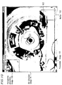
- Figure 2 shows a display screen 20 of the computer system 13 which displays the digital information obtained by capturing, using the video camera 11, an all-direction image 21 of the 360° environment obtained by the hyperboloidal mirror 10 and converting by the image processing board 12.
- video (image) of the 360° environment i.e., a certain range of image projected on the hyperboloidal mirror 10
- Moving objects are detected using image processing as described later, and the data of each moving object are labeled so as to be managed and identified. Therefore, one or more moving objects included in an image can be tracked.
- Figure 3 is a panoramic image 30 obtained by subjecting the 360° all-direction image of Figure 2 to image processing described later (panorama conversion) in order to make it easy to view the 360° all-direction image.
- image processing i.e., image
- Moving objects 33 and 34 detected in the panoramic image 30 are subjected to image processing as described later to give the moving objects 33 and 34 respective markers 31 and 32, thereby making it easy to identify the moving objects 33 and 34.
- the sizes of the markers 31 and 32 are determined depending on the areas of the moving objects 33 and 34 detected in the panoramic image 30, it is easier to identify the moving objects 33 and 34.
- the panoramic image 30 is an image obtained by developing (spreading out) the all-direction video obtained by the hyperboloidal mirror 10 in a ⁇ direction, and includes distortion due to the hyperboloidal mirror 10. Therefore, the panoramic image 30 is subjected to image processing as described later to be converted into a perspective projection image 40 which is an image viewed from a focus of the hyperboloidal mirror 10 as shown in Figure 4 (an image photographed by a typical camera), thereby obtaining an image without distortion.
- Algorithms for panorama conversion and perspective projection conversion for images obtained by the hyperboloidal mirror 10 are disclosed Japanese Laid-Open Publication No. 6-295333, for example.
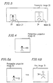
- the perspective projection image 40 of Figure 4 is an image without distortion converted from the all-direction image 21 of Figure 2, and is also regarded as an image cut from the panoramic image 30 of Figure 3. Therefore, by changing portions to be cut off the panoramic image 30 using an image processing technique as described later, operations equivalent to pan and tilt can be performed without moving a camera as shown in Figures 5A and 5B .
- Figure 5A is a perspective projection image 50
- Figure 5B is a perspective projection image 51 after a pan operation.
- the all-direction video obtained by the hyperboloidal mirror 10 is converted to digital information by the image processing board 12 as described above, three kinds of data (R, G and B) on color video are obtained when a video camera captures color images.
- the image processing described later may not be performed for all three kinds of data (R, G and B), and, for example, only one kind of data (e.g., R) is used to detect a moving object, thereby reducing the amount of image processing and therefore speeding up the processing.
- the all-direction image 21 shown in Figure 2 is obtained by processing only R data.
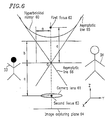
- a coordinate system is defined as follows.
- the intersection 0 of asymptotic lines 65 and 66 is an origin, a horizontal plane is formed by the X axis and the Y axis, and a vertical axis (a direction connecting between the first focus 62 and the second focus 63 ) is the Z axis.
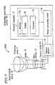
- FIG 7 is a diagram showing a schematic configuration of a moving object tracking apparatus 2000 according to an example of the present invention.
- the moving object tracking apparatus 2000 includes a hyperboloidal mirror 70, a protection dome 71, a holder 72, a video camera 73, a camera holder 74, and an information processing section 90.
- the information processing section 90 includes a camera adapter 75, an image processing board 76, and a personal computer 77.
- the protection dome 71 made of acryl is attached to the hyperboloidal mirror 70, and the video camera 73 is attached via the holder 72 in order to capture information on the environment.
- the video camera 73 is supported by the camera holder 74 so as to prevent the camera 73 from falling.
- a viewing angle is obtained where the horizontal viewing angle is 360°, the vertical viewing angle is about 90°, the elevation angle is about 25°, and the depression angle is about 65°.
- metal is shaped to produce the hyperboloidal mirror 70, a plastic material-may be shaped using a mold, and a resultant surface thereof is subjected to metal deposition in mass production, thereby making it possible to reduce production cost.
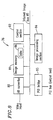
- Figure 8 is a diagram showing an internal structure block in the image processing board 76 of Figure 7 and is used for explaining an operation of the internal structure block. All-direction image data converted to an RGB signal by the camera adapter 75 is converted to digital data having 8 bits in each color of R, G and B by an AD converter 80, and the resultant digital data is stored in an image memory 81. Data in the image memory 81 is transferred via an internal image bus 85 to an image processing section 84, and various kinds of image processing ( Figure 11 ) are performed using the above-described image processing library at high speed. Processed data is transferred via a PCI bridge 83 to a PCI bus of the extended slot of the personal computer 77 and is stored in a memory 77a of the personal computer 77.
- the data is displayed on a display 78.
- a keyboard 79 shown in Figure 7 is a means for receiving commands to start and end the processes of the moving object tracking apparatus 2000.
- the control section 82 shown in Figure 8 controls transmission and reception of host commands, the image memory 81, and the image processing section 84.
- Figure 9 shows a window of the display 78 displaying data stored in the memory 77a which is obtained by transferring all-direction image data captured in the image memory 81 of the image processing board 76 to the personal computer 77.
- the screen size of this window is a VGA screen of 640 x 480 pixels, for example.
- the window corresponds to the display screen 20 of Figure 2.
- the all-direction image 91 is displayed on a VGA screen having a resolution of 640 ⁇ 480 pixels, the resolution of 410,000 pixels of the CCD camera is sufficient. It should be noted that a camera having a higher resolution is required to increase the resolution of an image.
- Figure 10 shows the above-described window into which a panoramic image 101 obtained by subjecting the all-direction image 91 of Figure 9 to panorama conversion and a perspective projection image 100 obtained by subjecting the all-direction image 91 to perspective projection conversion are integrated.
- the panoramic image 101 has a size of 640 ⁇ 160 pixels while the perspective projection image 100 has a size of 120 x 120 pixels.
- a marker 102 is given to a moving object 103 in the panoramic image 101.
- All-direction image data is converted to an RGB signal by the camera adapter 75 of Figure 7, the RGB signal is converted to digital data having 8 bits in each color of R, G and B by the AD converter 80 of Figure 8, and the digital data is stored in the image memory 81.
- step 110 of Figure 11 all-direction image frame data captured in a previous frame and all-direction image frame data captured in a current frame are subject to a subtraction operation so as to calculate a frame difference.
- a maximum pixel value in a 3 ⁇ 3 pixel window is determined in step 111.
- the image is expanded.
- the expansion of the image is carried out in order to unite the separate objects.
- an 256-gray level image is converted to a 2-gray level image having one gray level for a background and the other gray level for a moving object to be tracked.
- the background having substantially no movement amount has a brightness difference of zero.
- the moving object has a brightness difference between a previous frame and a current frame, so that the brightness difference greater than or equal to a predetermined value is detected as a moving object.
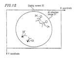
- the moving object can be tracked by detecting such a brightness difference between each frame. Referring to Figure 12, the positions of the moving objects 33 and 34 in the current frame are different from the respective positions of the moving objects 33' and 34' in the previous frame. Therefore, brightness differences are present at the positions of the moving objects 33, 34, 33' and 34'. Moving objects can be tracked by detecting such brightness differences between each frame.
- step 113 connected regions in the binary image data are numbered (labeled).
- labeling the area or the center of mass of a connected region (described later) can be extracted for each label. Further, by labeling, a plurality of moving objects can be distinguished.
- an X-Y coordinate system where the upper left corner is an origin is used as a coordinate system for the all-direction image 21 in a VGA screen of 640 x 480 pixels (the display screen 20 ).
- step 114 the area (the number of pixels) of each labeled connected region is calculated.
- step 115 whether the area is greater than or equal to a threshold is determined. If the area is less than the threshold, the labeled connected region is determined as noise. Therefore, the process flow of the present invention is resistant to noise.
- step 116 the extracted areas are sorted in decreasing order of size.
- step 117 the barycentric coordinates are calculated for each of the n largest areas.
- the barycentric coordinates of each connected region labeled in step 113 are calculated by a first-order moment calculated for the connected region being divided by the area (0-order moment).
- step 118 the n sets of barycentric coordinates in a current frame extracted in step 117 and the n sets of barycentric coordinates in a previous frame are identified, thereby detecting moving objects and tracking each moving object.
- step 119 moving objects can be detected and the barycentric coordinates thereof can be calculated. Therefore, in step 119, a radius and an angle of each moving object in a polar coordinate system are calculated based on the barycentric coordinates thereof.
- step 120 the all-direction image of a current frame is converted to a panoramic image.
- step 121 the all-direction image of a current frame is converted to a perspective projection image.
- step 120 when the panorama conversion is carried out, a marker is given to a moving object detected in step 119.
- step 110 In the moving object detection flow from step 110 to step 119, only G data of RGB data may be used so as to speed up the detection processing of moving objects, for example.
- step 120 and step 121 all RGB data are used so as to process a color image.
- moving objects are detected from all-direction image data in a current frame, and the all-direction image data can be converted to panoramic image data and perspective projection image data having markers.
- the converted image data is stored in the memory 77a of the personal computer 77, and transferred to the display 78 on which the image data is presented ( Figures 9 and 10 ).
- a next all-direction image is captured and subsequent frame data is processed, so that a moving image can be displayed.
- panorama conversion will be described with reference to Figures 13A and 13B.
- an object P (pixel) represented by coordinates (x, y) in a display screen 130 shown in Figure 13A can be projected to a panorama screen 132 shown in Figure 13B by calculating a radius r and an angle ⁇ of the object P in an all-direction image 131 where the coordinates of the center of the all-direction image 131 is (Cx, Cy).
- a radius r and an angle ⁇ of the object P in an all-direction image 131 where the coordinates of the center of the all-direction image 131 is (Cx, Cy).
- the coordinates in the all-direction image 131 calculated based on the coordinate system of the panoramic image 132 corresponding to all pixels in the panoramic image 132 are previously prepared as a table 86 ( Figure 8 ), and panorama conversion is carried out only by referencing the table 86.
- the table 86 is stored in the image memory 81, for example.
- a corresponding x coordinate is calculated in advance in accordance with formula (3) and a corresponding y coordinate is calculated in advance in accordance with formula (4).
- These x and y coordinates are stored in respective tables tbx and tby.
- the angle ⁇ ranges from 0° to 360° in 1/100° steps and the radius r ranges from 0 pixel to 160 pixels. Therefore, the size of the panoramic image 101 is 160 pixels in a lengthwise direction as shown in Figure 10.
- a pan operation can be performed in the panoramic image 132 by adding an offset toeach angle ⁇ when preparing the table. Therefore, such a pan operation can be performed in the panoramic image 132 at high speed by image processing.
- a marker adding operation since the radius and the angle of a moving object are determined in step 119 ( Figure 11). a marker is displayed (added) at a corresponding portion in a panoramic image based on such information.
- FIG. 14A For example, a sector portion surrounded by A, B, C and D in an all-direction image 141 on a display screen 140 shown in Figure 14A is subjected to perspective projection conversion.
- a radius r and an angle ⁇ of an object P (pixel) designated as coordinates (x, y) with reference to the coordinate of the center (Cx, Cy) of the all-direction image 141 are determined.
- the sector portion is projected onto a panoramic image 142 as a perspective projection image 143 as shown in Figure 14B.
- to perform such a conversion operation for each pixel is time-consuming.
- the coordinates in the all-direction image 141 corresponding to all pixels in the panoramic image 142 are previously prepared as the table 86 ( Figure 8 ), and perspective projection conversion is carried out only by referencing the table 86.
- a pixel represented by coordinates (r, ⁇ ) in the perspective projection image 143 ( Figure 14B ) is converted to coordinates (x, y) in the all-direction image 141 using formulas (3) and (4).
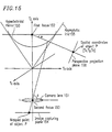
- the three-dimensional coordinates of the object P are (Tx, Ty, Tz)
- an angle of the object P viewed from a first focus 152 of a hyperboloidal mirror 150 with respect to a Tx axis is ⁇
- an angle of the object P projected on the hyperboloidal mirror 150 viewed from the center of a camera lens 151 of the video camera 151 with respect to the Tx axis is ⁇
- a
- a radius r and an angle ⁇ are calculated in advance for a set of coordinates (Tx, Ty, Tz) corresponding to each pixel on the perspective projection plane 156 in accordance with formulas (7) and (8) to prepare a ⁇ -coordinate table tb ⁇ and a r-coordinate table tbr as a portion of the table 86.
- the size of the perspective projection plane 156 is 120 ⁇ 120 pixels as described above, for example. Therefore, this size corresponds to the viewing angle obtained when assuming the video camera 73 is placed at the first focus 152 of the hyperboloidal mirror 150.
- each pixel on the perspective projection plane 156 can be converted to polar coordinates (r, ⁇ ) on the all-direction image 141 only by referencing the table tb ⁇ and the table tbr. Thereafter, the polar coordinates (r, ⁇ ) are converted to coordinates (x, y) on the the all-direction image 141 only by referencing the table tbx and the table tby.
- a pan operation can be performed in the perspective projection image 143 by adding an offset to an angle ⁇ when producing the table tb ⁇ , as in the panoramic image 142.
- a tilt operation can also be performed in the perspective projection image 143 by preparing a specialized table tbtr of a radius r.
- the tilt table tbtr lists a radius obtained by formulas (6) and (8) with respect to an angle a obtained by a tilt angle. Therefore, a pan operation and a tilt operation of the perspective projection image 143 can be performed by image processing at high speed.
- the processes in steps 110 to 114 and step 117 of Figure 11 are performed using functions included in an image processing library contained in an image processing board.
- the detection of a moving object is performed using only G data of RGB data.
- An all-direction image is converted to a panoramic image or a perspective projection image using a plurality of tables previously prepared. Therefore, a moving Image processing having a rate of 10 frames per second can be obtained in this example.
- an image processing board having a processing rate three times that of the above-described image processing board is required.
- the processes in steps 115, 116, 118 and 119 may be performed by a CPU of a personal computer rather than an image processing board.
- an optical system including a hyperboloidal mirror and a stationary camera are used instead of a mechanical driving portion. Therefore, maintenance is substantially not required during long-time operation, and highly reliable and stable operation can be realized. Further, only one camera is required, resulting in an inexpensive moving object tracking apparatus. Furthermore, visual field information on the 360° environment can be captured simultaneously. Therefore, losing track of a moving object is unlikely, and it is also possible to track a moving object which moves around the camera.
- An all-direction image obtained by using a hyperboloidal mirror in an optical system can be converted to a panoramic image so as to be easily viewed, or to a perspective projection image to obtain an image substantially without distortion. Therefore, recognition precision of a moving object can be improved.
- the moving object tracking apparatus of the present invention can be used in various applications, such as an indoor or outdoor surveillance apparatus, in a locomotive robot, and in a vehicle.
- Detecting and tracking a moving object can be realized by the above-described simple algorithms.
- the modification of a viewing angle, such as pan or tilt, can be performed.
- complicated circuitry for controlling the movements of a camera as in the conventional technology is not required. Therefore, the entire system can be made simple.
- a moving object tracking apparatus handling color moving images can also be made small.
- image information processing is carried out using a conversion table previously prepared depending on the resolution of a captured image, thereby speeding up image information processing. Further, color moving images can be processed at high speed by subjecting one color data of RGB data to image processing.
Landscapes
- Physics & Mathematics (AREA)
- Electromagnetism (AREA)
- Engineering & Computer Science (AREA)
- General Physics & Mathematics (AREA)
- Radar, Positioning & Navigation (AREA)
- Remote Sensing (AREA)
- Closed-Circuit Television Systems (AREA)
- Studio Devices (AREA)
Abstract
Description
Claims (10)
- A moving object tracking apparatus for detecting and tracking one or more moving objects in an environment, comprising:wherein the information processing section detects and tracks the one or more moving objects based on the image information.an optical system including a hyperboloidal mirror for capturing visual field information on a 360° environment;a single stationary camera for converting the captured visual field information to image information; andan information processing section for processing the image information;
- A moving object tracking apparatus according to claim 1, wherein:the image information includes all-direction image information; andthe information processing section converts at least a portion of the all-direction image information to panoramic image information.
- A moving object tracking apparatus according to claim 2, wherein the information processing section provides a marker to each of the one or more moving objects in the panoramic image information.
- A moving object tracking apparatus according to claim 3, wherein the information processing section provides a marker to each of the one or more moving objects depending on a size of each of the one or more moving objects.
- A moving object tracking apparatus according to any preceding claim, wherein:the image information includes all-direction image information; andthe information processing section converts at least a portion of the all-direction image information to perspective projection image information.
- A moving object tracking apparatus according to any preceding claim, wherein the information processing section processes the image information using a previously prepared table.
- A moving object tracking apparatus according to any preceding claim, wherein the information processing section processes the image information using only one kind of data out of RGB data in the image information.
- A moving object tracking apparatus according to any preceding claim, wherein the information processing section detects the one or more moving objects based on a brightness difference between predetermined frame information and frame information previous to the predetermined frame information of the image information.
- Apparatus comprising: stationary image-information-capture-means for capturing, by means of a hyperboloidal mirror, image information from a 360 degree field of view; and processing means for processing said captured information to detect, and preferably track, one or more objects in said field of view.
- A method comprising the steps of: capturing, by means of a hyperboloidal mirror, image information from a 360 degree field of view; and processing said captured information to detect, and preferably track, one or more objects in said field of view.
Applications Claiming Priority (2)
| Application Number | Priority Date | Filing Date | Title |
|---|---|---|---|
| JP2000247885 | 2000-08-17 | ||
| JP2000247885A JP2002064812A (en) | 2000-08-17 | 2000-08-17 | Moving object tracking device |
Publications (3)
| Publication Number | Publication Date |
|---|---|
| EP1182465A2 true EP1182465A2 (en) | 2002-02-27 |
| EP1182465A3 EP1182465A3 (en) | 2004-02-04 |
| EP1182465B1 EP1182465B1 (en) | 2006-10-04 |
Family
ID=18737887
Family Applications (1)
| Application Number | Title | Priority Date | Filing Date |
|---|---|---|---|
| EP01306762A Expired - Lifetime EP1182465B1 (en) | 2000-08-17 | 2001-08-08 | Moving object tracking apparatus |
Country Status (4)
| Country | Link |
|---|---|
| US (1) | US20020024599A1 (en) |
| EP (1) | EP1182465B1 (en) |
| JP (1) | JP2002064812A (en) |
| DE (1) | DE60123534T2 (en) |
Cited By (3)
| Publication number | Priority date | Publication date | Assignee | Title |
|---|---|---|---|---|
| EP1892665A3 (en) * | 2006-08-25 | 2010-03-31 | Imay Software Co. Ltd. | Entire-view video image process system and method thereof |
| WO2010041240A1 (en) * | 2008-10-12 | 2010-04-15 | Rafael Advanced Defense Systems Ltd. | Method and system for displaying a panoramic view to an operator |
| CN103248806A (en) * | 2013-04-26 | 2013-08-14 | 黑龙江科技学院 | Device for single camera to achieve spatial 360 degree annular panoramic and local precise imaging |
Families Citing this family (29)
| Publication number | Priority date | Publication date | Assignee | Title |
|---|---|---|---|---|
| JP4211292B2 (en) | 2002-06-03 | 2009-01-21 | ソニー株式会社 | Image processing apparatus, image processing method, program, and program recording medium |
| JP4614653B2 (en) * | 2003-12-12 | 2011-01-19 | ソニー株式会社 | Monitoring device |
| JP4587166B2 (en) * | 2004-09-14 | 2010-11-24 | キヤノン株式会社 | Moving body tracking system, photographing apparatus, and photographing method |
| TWI258682B (en) * | 2005-05-06 | 2006-07-21 | Sunplus Technology Co Ltd | Interactive video game system |
| KR100715026B1 (en) | 2005-05-26 | 2007-05-09 | 한국과학기술원 | Single camera omnidirectional binocular image acquisition device |
| JP4685561B2 (en) * | 2005-09-12 | 2011-05-18 | 株式会社日立国際電気 | Display method of camera system and camera system |
| US20070152157A1 (en) * | 2005-11-04 | 2007-07-05 | Raydon Corporation | Simulation arena entity tracking system |
| US7542671B2 (en) * | 2006-06-30 | 2009-06-02 | Opt Corporation | Omni directional photographing device |
| US8072482B2 (en) | 2006-11-09 | 2011-12-06 | Innovative Signal Anlysis | Imaging system having a rotatable image-directing device |
| TWI398819B (en) * | 2007-02-14 | 2013-06-11 | Chung Shan Inst Of Science | Fast target tracking device |
| JP4288428B2 (en) * | 2007-03-15 | 2009-07-01 | 日本電気株式会社 | Video analysis system and video analysis method |
| US20080306708A1 (en) * | 2007-06-05 | 2008-12-11 | Raydon Corporation | System and method for orientation and location calibration for image sensors |
| JP5469894B2 (en) * | 2008-07-05 | 2014-04-16 | 株式会社トプコン | Surveying device and automatic tracking method |
| US9092951B2 (en) * | 2008-10-01 | 2015-07-28 | Ncr Corporation | Surveillance camera assembly for a checkout system |
| JP5469899B2 (en) * | 2009-03-31 | 2014-04-16 | 株式会社トプコン | Automatic tracking method and surveying device |
| US9430923B2 (en) | 2009-11-30 | 2016-08-30 | Innovative Signal Analysis, Inc. | Moving object detection, tracking, and displaying systems |
| US8675090B2 (en) * | 2010-12-15 | 2014-03-18 | Panasonic Corporation | Image generating apparatus, image generating method, and recording medium |
| US8947524B2 (en) | 2011-03-10 | 2015-02-03 | King Abdulaziz City For Science And Technology | Method of predicting a trajectory of an asteroid |
| JP5906028B2 (en) | 2011-06-22 | 2016-04-20 | キヤノン株式会社 | Image processing apparatus and image processing method |
| CN102895093A (en) * | 2011-12-13 | 2013-01-30 | 冷春涛 | Walker aid robot tracking system and walker aid robot tracking method based on RGB-D (red, green and blue-depth) sensor |
| JP5896781B2 (en) * | 2012-02-29 | 2016-03-30 | キヤノン株式会社 | Image processing apparatus and image processing method |
| US10474921B2 (en) | 2013-06-14 | 2019-11-12 | Qualcomm Incorporated | Tracker assisted image capture |
| US10139819B2 (en) | 2014-08-22 | 2018-11-27 | Innovative Signal Analysis, Inc. | Video enabled inspection using unmanned aerial vehicles |
| KR102676837B1 (en) | 2016-12-16 | 2024-06-21 | 삼성전자주식회사 | Display apparatus and control method thereof |
| CN106961597B (en) * | 2017-03-14 | 2019-07-26 | 深圳Tcl新技术有限公司 | The target tracking display methods and device of panoramic video |
| JP6894398B2 (en) * | 2018-03-28 | 2021-06-30 | Kddi株式会社 | Object tracking device, object tracking method, and object tracking program |
| CN111882578B (en) * | 2019-07-19 | 2025-03-07 | 广州虎牙科技有限公司 | Foreground image acquisition method, foreground image acquisition device and electronic device |
| JP7472553B2 (en) * | 2020-03-09 | 2024-04-23 | 株式会社リコー | IMAGE PROCESSING SYSTEM, INFORMATION PROCESSING APPARATUS AND METHOD |
| JP7799431B2 (en) * | 2021-10-26 | 2026-01-15 | キヤノン株式会社 | Information processing device, information processing method, and program |
Family Cites Families (6)
| Publication number | Priority date | Publication date | Assignee | Title |
|---|---|---|---|---|
| EP0715743B1 (en) * | 1993-08-25 | 2001-03-07 | The Australian National University | Panoramic imaging system |
| KR100235344B1 (en) * | 1994-12-29 | 1999-12-15 | 전주범 | Foreground / background image selection device with region division coding |
| US5953449A (en) * | 1996-03-15 | 1999-09-14 | Kabushiki Kaisha Toshiba | Measuring apparatus and measuring method |
| US6215519B1 (en) * | 1998-03-04 | 2001-04-10 | The Trustees Of Columbia University In The City Of New York | Combined wide angle and narrow angle imaging system and method for surveillance and monitoring |
| US6226035B1 (en) * | 1998-03-04 | 2001-05-01 | Cyclo Vision Technologies, Inc. | Adjustable imaging system with wide angle capability |
| US6304285B1 (en) * | 1998-06-16 | 2001-10-16 | Zheng Jason Geng | Method and apparatus for omnidirectional imaging |
-
2000
- 2000-08-17 JP JP2000247885A patent/JP2002064812A/en active Pending
-
2001
- 2001-08-08 EP EP01306762A patent/EP1182465B1/en not_active Expired - Lifetime
- 2001-08-08 DE DE60123534T patent/DE60123534T2/en not_active Expired - Lifetime
- 2001-08-16 US US09/931,962 patent/US20020024599A1/en not_active Abandoned
Cited By (4)
| Publication number | Priority date | Publication date | Assignee | Title |
|---|---|---|---|---|
| EP1892665A3 (en) * | 2006-08-25 | 2010-03-31 | Imay Software Co. Ltd. | Entire-view video image process system and method thereof |
| WO2010041240A1 (en) * | 2008-10-12 | 2010-04-15 | Rafael Advanced Defense Systems Ltd. | Method and system for displaying a panoramic view to an operator |
| US8730127B2 (en) | 2008-10-12 | 2014-05-20 | Rafael Advanced Defense Systems Ltd. | Method and system for displaying a panoramic view to an operator |
| CN103248806A (en) * | 2013-04-26 | 2013-08-14 | 黑龙江科技学院 | Device for single camera to achieve spatial 360 degree annular panoramic and local precise imaging |
Also Published As
| Publication number | Publication date |
|---|---|
| US20020024599A1 (en) | 2002-02-28 |
| EP1182465B1 (en) | 2006-10-04 |
| DE60123534D1 (en) | 2006-11-16 |
| EP1182465A3 (en) | 2004-02-04 |
| DE60123534T2 (en) | 2007-06-06 |
| JP2002064812A (en) | 2002-02-28 |
Similar Documents
| Publication | Publication Date | Title |
|---|---|---|
| EP1182465B1 (en) | Moving object tracking apparatus | |
| US8957971B2 (en) | Image processing device and method, image processing system, and image processing program | |
| JP4243767B2 (en) | Fisheye lens camera device and image extraction method thereof | |
| JP4048511B2 (en) | Fisheye lens camera device and image distortion correction method thereof | |
| JP4268206B2 (en) | Fisheye lens camera device and image distortion correction method thereof | |
| US6215519B1 (en) | Combined wide angle and narrow angle imaging system and method for surveillance and monitoring | |
| CN101790048B (en) | Intelligent camera system and method | |
| US7256817B2 (en) | Following device | |
| KR20020007211A (en) | Omnidirectional vision sensor | |
| JP2004354257A (en) | Calibration slippage correction device, and stereo camera and stereo camera system equipped with the device | |
| CN114511595B (en) | Multi-mode cooperation and fusion target tracking method, device, system and medium | |
| JP2003304561A (en) | Stereo image processing device | |
| JP4198536B2 (en) | Object photographing apparatus, object photographing method and object photographing program | |
| JPH06167564A (en) | Position measuring system and device using fish eye lens | |
| JP2003061075A (en) | Object-tracking device, object-tracking method and intruder monitor system | |
| JP2002027449A (en) | Moving object identification method and moving object identification device | |
| KR102598630B1 (en) | Object tracking pan-tilt apparatus based on ultra-wide camera and its operation method | |
| JPH0793558A (en) | Image monitoring device | |
| JP3828096B2 (en) | Object tracking device | |
| JPH1118007A (en) | Omnidirectional image display system | |
| JP2002101408A (en) | Supervisory camera system | |
| JP2004072240A (en) | Imaging apparatus, and tracking system and scanner using the same | |
| JP2011090258A (en) | Wide-angle image display control method, device for the same, and wide-angle image taking device | |
| JP2001194141A (en) | Moving object position detection method | |
| KR20100050264A (en) | Optical axis error compensation system of the zoom camera, the method of the same, and the zoom camera provided for the compensation function of the optical axis error |
Legal Events
| Date | Code | Title | Description |
|---|---|---|---|
| PUAI | Public reference made under article 153(3) epc to a published international application that has entered the european phase |
Free format text: ORIGINAL CODE: 0009012 |
|
| AK | Designated contracting states |
Kind code of ref document: A2 Designated state(s): AT BE CH CY DE DK ES FI FR GB GR IE IT LI LU MC NL PT SE TR |
|
| AX | Request for extension of the european patent |
Free format text: AL;LT;LV;MK;RO;SI |
|
| PUAL | Search report despatched |
Free format text: ORIGINAL CODE: 0009013 |
|
| AK | Designated contracting states |
Kind code of ref document: A3 Designated state(s): AT BE CH CY DE DK ES FI FR GB GR IE IT LI LU MC NL PT SE TR |
|
| AX | Request for extension of the european patent |
Extension state: AL LT LV MK RO SI |
|
| RIC1 | Information provided on ipc code assigned before grant |
Ipc: 7G 01S 3/786 A Ipc: 7G 06T 3/00 B Ipc: 7H 04N 5/14 B Ipc: 7G 06T 7/20 B |
|
| 17P | Request for examination filed |
Effective date: 20040803 |
|
| 17Q | First examination report despatched |
Effective date: 20040908 |
|
| AKX | Designation fees paid |
Designated state(s): DE FR GB |
|
| GRAP | Despatch of communication of intention to grant a patent |
Free format text: ORIGINAL CODE: EPIDOSNIGR1 |
|
| GRAS | Grant fee paid |
Free format text: ORIGINAL CODE: EPIDOSNIGR3 |
|
| GRAA | (expected) grant |
Free format text: ORIGINAL CODE: 0009210 |
|
| AK | Designated contracting states |
Kind code of ref document: B1 Designated state(s): DE FR GB |
|
| REG | Reference to a national code |
Ref country code: GB Ref legal event code: FG4D |
|
| REF | Corresponds to: |
Ref document number: 60123534 Country of ref document: DE Date of ref document: 20061116 Kind code of ref document: P |
|
| ET | Fr: translation filed | ||
| PLBE | No opposition filed within time limit |
Free format text: ORIGINAL CODE: 0009261 |
|
| STAA | Information on the status of an ep patent application or granted ep patent |
Free format text: STATUS: NO OPPOSITION FILED WITHIN TIME LIMIT |
|
| 26N | No opposition filed |
Effective date: 20070705 |
|
| PGFP | Annual fee paid to national office [announced via postgrant information from national office to epo] |
Ref country code: FR Payment date: 20100824 Year of fee payment: 10 Ref country code: DE Payment date: 20100812 Year of fee payment: 10 |
|
| PGFP | Annual fee paid to national office [announced via postgrant information from national office to epo] |
Ref country code: GB Payment date: 20100811 Year of fee payment: 10 |
|
| GBPC | Gb: european patent ceased through non-payment of renewal fee |
Effective date: 20110808 |
|
| REG | Reference to a national code |
Ref country code: FR Ref legal event code: ST Effective date: 20120430 |
|
| REG | Reference to a national code |
Ref country code: DE Ref legal event code: R119 Ref document number: 60123534 Country of ref document: DE Effective date: 20120301 |
|
| PG25 | Lapsed in a contracting state [announced via postgrant information from national office to epo] |
Ref country code: GB Free format text: LAPSE BECAUSE OF NON-PAYMENT OF DUE FEES Effective date: 20110808 Ref country code: FR Free format text: LAPSE BECAUSE OF NON-PAYMENT OF DUE FEES Effective date: 20110831 |
|
| PG25 | Lapsed in a contracting state [announced via postgrant information from national office to epo] |
Ref country code: DE Free format text: LAPSE BECAUSE OF NON-PAYMENT OF DUE FEES Effective date: 20120301 |