EP1182370A2 - Sealing system for a spherical bearing - Google Patents
Sealing system for a spherical bearing Download PDFInfo
- Publication number
- EP1182370A2 EP1182370A2 EP01118478A EP01118478A EP1182370A2 EP 1182370 A2 EP1182370 A2 EP 1182370A2 EP 01118478 A EP01118478 A EP 01118478A EP 01118478 A EP01118478 A EP 01118478A EP 1182370 A2 EP1182370 A2 EP 1182370A2
- Authority
- EP
- European Patent Office
- Prior art keywords
- seal
- spherical bearing
- spherical
- spherical surface
- sealing system
- Prior art date
- Legal status (The legal status is an assumption and is not a legal conclusion. Google has not performed a legal analysis and makes no representation as to the accuracy of the status listed.)
- Granted
Links
Images




Classifications
-
- F—MECHANICAL ENGINEERING; LIGHTING; HEATING; WEAPONS; BLASTING
- F16—ENGINEERING ELEMENTS AND UNITS; GENERAL MEASURES FOR PRODUCING AND MAINTAINING EFFECTIVE FUNCTIONING OF MACHINES OR INSTALLATIONS; THERMAL INSULATION IN GENERAL
- F16C—SHAFTS; FLEXIBLE SHAFTS; ELEMENTS OR CRANKSHAFT MECHANISMS; ROTARY BODIES OTHER THAN GEARING ELEMENTS; BEARINGS
- F16C33/00—Parts of bearings; Special methods for making bearings or parts thereof
- F16C33/72—Sealings
- F16C33/74—Sealings of sliding-contact bearings
-
- F—MECHANICAL ENGINEERING; LIGHTING; HEATING; WEAPONS; BLASTING
- F16—ENGINEERING ELEMENTS AND UNITS; GENERAL MEASURES FOR PRODUCING AND MAINTAINING EFFECTIVE FUNCTIONING OF MACHINES OR INSTALLATIONS; THERMAL INSULATION IN GENERAL
- F16C—SHAFTS; FLEXIBLE SHAFTS; ELEMENTS OR CRANKSHAFT MECHANISMS; ROTARY BODIES OTHER THAN GEARING ELEMENTS; BEARINGS
- F16C23/00—Bearings for exclusively rotary movement adjustable for aligning or positioning
- F16C23/02—Sliding-contact bearings
- F16C23/04—Sliding-contact bearings self-adjusting
- F16C23/043—Sliding-contact bearings self-adjusting with spherical surfaces, e.g. spherical plain bearings
- F16C23/045—Sliding-contact bearings self-adjusting with spherical surfaces, e.g. spherical plain bearings for radial load mainly, e.g. radial spherical plain bearings
-
- F—MECHANICAL ENGINEERING; LIGHTING; HEATING; WEAPONS; BLASTING
- F16—ENGINEERING ELEMENTS AND UNITS; GENERAL MEASURES FOR PRODUCING AND MAINTAINING EFFECTIVE FUNCTIONING OF MACHINES OR INSTALLATIONS; THERMAL INSULATION IN GENERAL
- F16C—SHAFTS; FLEXIBLE SHAFTS; ELEMENTS OR CRANKSHAFT MECHANISMS; ROTARY BODIES OTHER THAN GEARING ELEMENTS; BEARINGS
- F16C43/00—Assembling bearings
- F16C43/02—Assembling sliding-contact bearings
Definitions
- the present invention relates to a sealing system for a spherical bearing in which a spherical surface of a split inner race is supported by an inner spherical surface of an outer race.
- a spherical bearing 31 in which a spherical surface 33a of an inner race 33 is slidably supported by an inner spherical surface 32a of an outer race 32 has been known.
- a shaft not shown fixed in an axial hole 33b provided on the inner race 33 is supported rotatably and oscillatory.
- a spherical bearing 31 wherein the inner race 33 is split at a given split surface 33c in such a manner that the inner race 33 is easily inserted into the inner spherical surface 32a of the outer race 32 when being assembled.
- a seal 35 made of silicon, nylon or rubber is hold by an annular retainer 34 made of steel while a side end portion of the retainer 34 is welded to an end surface 32b of the outer race 32 by means of an electron beam as shown in Figs. 6 and 7.
- the seal 35 may be twisted while the inner race 33 is under a sliding operation and a gap is generated between the seal 35 and the spherical surface 33a of the inner race 33 resulting in a deterioration of the sealing function.
- the retainer 34 once fixed needs to be removed from the end surface 32b of the outer race 32 for welding again.
- the sealing system is formed in such a manner that the seal 35 is extended inside an edge portion 32c of the inner spherical surface 32a of the outer race 32, the seal 35 gives a limitation to a swing angle of a shaft not shown fitted to the inner race 33 resulting in a difficulty to obtain a desired swing angle.
- the present invention has been made in the light of the above, and an object of the present invention is to provide a sealing system of a spherical bearing in such a manner as to maintain a high sealing function with a simple structure and to avoid a limitation of a swing angle.
- an annular seal groove is provided to the inner spherical surface of the outer race with a given space from an edge of the inner spherical surface of the outer race.
- the spherical bearing can be sealed in such a manner as to abut the seal fitted in the seal groove to the spherical surface of the inner race.
- a side wall of a seal groove wherein a seal is fit is bent inside.
- the seal is fixed more tightly to the seal groove by a deformation of a section of the seal groove. And, a sealing function can be improved by closely abutting the seal to the spherical surface of the inner race in such a manner that the seal is deformed.
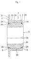
- FIG. 1 An embodiment of a sealing system of a spherical bearing of the present invention is explained with reference to Figs. 1- 5. First, an outline thereof is hereinafter explained.
- the sealing system of a spherical bearing 1 of the embodiment of the present invention as shown in Fig. 1 is constituted in such a manner that annular seal grooves 4 are provided on an inner spherical surface 2a of an outer race 2 with a given space from edges 2b of the inner spherical surface 2a, seals 5 are fitted in the seal grooves 4, and the spherical bearing 1 is sealed by abutting the seals 5 to a spherical surface 3a of an inner race 3.
- a sealing function is improved in such a manner as to fix the seals 5 tightly by the seal grooves 4 by deforming a section of the seal grooves 4 through bending side walls 4a of the seal grooves 4 fitted into the seal 5 and to abut the seal 5 to the spherical surface 3a of the inner race 3 by deforming the seal 5.
- the spherical bearing 1 of the embodiment of the present invention is constituted as that the spherical surface 3a of the inner race 3 is slidably supported by the inner spherical surface 2a of the outer race 2.
- the outer race 2 is substantially formed in a cylindrical shape with a flange 2c on its one side and its outer circumference 2d is fit in a housing not shown.
- the inner spherical surface 2a formed in the inner surface of the outer race 2 is coated with a sliding liner such as fluorescent resin.
- a sliding liner such as fluorescent resin
- the inner race 3 is split into two at a split surface 3b so as to achieve an easy insertion into the inner spherical surface 2a of the outer race 2, and a shaft hole 3c in which a shaft not shown is fixed is formed inside thereof.
- this spherical bearing 1 is structured in such a manner that a shaft fixed in the shaft hole 3c of the inner race 3 is rotatably and oscillatory supported by sliding the spherical surface 3a of the inner race 3 on the inner spherical surface 2a of the outer race 2 through the sliding liner.
- the sealing system of the spherical bearing 1 of the embodiment of the present invention is constituted with seal grooves 4 formed on both sides on the inner spherical surface 2a of the outer race 2 and seals 5 fitted in the seal grooves 4.
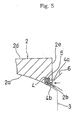
- the seal grooves 4 are annularly formed on the inner spherical surface 2a of the outer race 2 with a side wall 4a having a given thickness (T in Fig. 3) defined by a distance between the seal grooves 4 and the end faces 2e of the outer race 2.
- T in Fig. 3 a given thickness
- an end surface 4b of the side wall 4a of the seal groove 4 is formed in a given diameter D in Fig. 3 so as to avoid an interference with a shaft not shown fixed in the inner race 3 which secures a swingable range of the shaft.
- the annularly formed seal 5 is made of silicon, nylon or rubber, and an inside curvature of the seal 5 is closely abutted to the spherical surface 3a of the inner race 3 to form a sealing system of the spherical bearing 1.
- the side wall 4a of the seal groove 4 is deformed by being bent inward with a press die 6 so as to tightly fit the seal 5 to the seal groove 4. And, since the seal 5 is pressed by the deformation of the side wall 4a, the inside curvature of the seal 5 is further tightly abutted to the spherical surface 3a of the inner race 3 so as to improve the sealing function of the spherical bearing 1.
- the sealing system of the spherical bearing 1 of the embodiment of the present invention is constituted in such a manner that the annular seal grooves 4 are formed on the inner spherical surface 2a of the outer race 2 and the seal 5 fitted in the seal groove 4 is abutted to the spherical surface 3a of the inner race 3 thereby avoiding connecting the retainer 34 provided with the seal 35 to the end surface 32b of the outer race 32 by welding, etc. which has been performed by the conventional sealing system of the spherical bearing 31 (see Figs. 6 and 7). Accordingly, manufacturing processes of the spherical bearing 1 can be rationalized.
- a plane surface will not be needed on the end surface 32b of the outer race 32 to connect the retainer 34 (see Figs. 6 and 7) so as to give more freedom in a design of the spherical bearing 1.
- the seal 5 can be tightly fixed by the seal groove 4; moreover, since the seal 5 is pressed according to the deformation of the side wall 4a, the seal 5 is closely abutted to the spherical surface 3a of the inner race 3 thereby increasing the sealing function of the spherical bearing 1. Further, even if the sealing function is deteriorated, the function can be easily recovered by repressing with the press die 6.
- a sealing system of a spherical bearing is constituted in such a manner that annular seal grooves are formed on an inner spherical surface of an outer race, seals fitted in the seal grooves are abutted to spherical surfaces of inner races.
- a retainer provided with a seal to be connected to an end of the outer race by welding, etc. thereby being able to rationalize manufacturing processes of the spherical bearing.
- a plane portion to be provided on an end surface of the outer race for connecting with the retainer, which gives more freedom for the design of the spherical bearing.
- the seal since a side wall of a seal groove is deformed by being bent inward with the press die, the seal is fixed more tightly by the seal groove; moreover, since the seal is pressed according to the deformation of the side wall of the seal groove, the seal can be more tightly abutted to the spherical surface of the inner race so as to improve the sealing function of the spherical bearing. Further, even if the sealing function is deteriorated, the function can be easily recovered by repressing with the press die.
Landscapes
- Engineering & Computer Science (AREA)
- General Engineering & Computer Science (AREA)
- Mechanical Engineering (AREA)
- Support Of The Bearing (AREA)
- Sealing Of Bearings (AREA)
- Sliding-Contact Bearings (AREA)
Abstract
Description
Claims (2)
- A sealing system of a spherical bearing characterized in that, in a spherical bearing in which spherical surfaces of a split type inner race are slidably supported by an inner spherical surface of an outer race, annular seal grooves are provided with a given space from an edge of said inner spherical surface of said outer race and seals are fit in said seal grooves.
- The sealing system of the spherical bearing according to Claim 1, wherein a side wall of said seal groove is bent inward.
Applications Claiming Priority (2)
| Application Number | Priority Date | Filing Date | Title |
|---|---|---|---|
| JP2000242664A JP2002054644A (en) | 2000-08-10 | 2000-08-10 | Seal structure of spherical slide bearing |
| JP2000242664 | 2000-08-10 |
Publications (3)
| Publication Number | Publication Date |
|---|---|
| EP1182370A2 true EP1182370A2 (en) | 2002-02-27 |
| EP1182370A3 EP1182370A3 (en) | 2004-02-11 |
| EP1182370B1 EP1182370B1 (en) | 2008-07-23 |
Family
ID=18733661
Family Applications (1)
| Application Number | Title | Priority Date | Filing Date |
|---|---|---|---|
| EP01118478A Expired - Lifetime EP1182370B1 (en) | 2000-08-10 | 2001-08-01 | Sealing system for a spherical bearing |
Country Status (4)
| Country | Link |
|---|---|
| US (1) | US6502993B2 (en) |
| EP (1) | EP1182370B1 (en) |
| JP (1) | JP2002054644A (en) |
| DE (1) | DE60134921D1 (en) |
Cited By (3)
| Publication number | Priority date | Publication date | Assignee | Title |
|---|---|---|---|---|
| GB2421058A (en) * | 2004-12-13 | 2006-06-14 | Minebea Co Ltd | A spherical bearing arrangement |
| DE102006044637A1 (en) * | 2006-09-19 | 2008-03-27 | Schaeffler Kg | Hinge bearing i.e. sliding bearing, has inner ring supported by clamping ring that is arranged at front side of inner ring, where clamping ring has rectangular cross section and is provided with chamfer, which is turned towards outer ring |
| GB2595681A (en) * | 2020-06-02 | 2021-12-08 | Minebea Mitsumi Inc | A spherical bearing arrangement |
Families Citing this family (15)
| Publication number | Priority date | Publication date | Assignee | Title |
|---|---|---|---|---|
| US7261488B2 (en) * | 2003-09-09 | 2007-08-28 | Illinois Tool Works Inc | Ball socket ring seal |
| US7168846B1 (en) | 2004-01-20 | 2007-01-30 | Lyco Manufacturing, Inc. | Rotary processing device |
| JP2007157237A (en) * | 2005-12-05 | 2007-06-21 | Kenwood Corp | Pickup unit |
| US9157480B2 (en) | 2006-07-19 | 2015-10-13 | Roller Bearing Company Of America, Inc. | Two stage seal for a bearing assembly |
| CN102046991A (en) * | 2008-05-28 | 2011-05-04 | 蒂姆肯公司 | Spherical bearing triple-lip seal |
| US8579218B2 (en) | 2010-09-29 | 2013-11-12 | Emerson Electric Co. | Food waste disposer with self-compensating bearing assembly |
| WO2012068237A1 (en) | 2010-11-16 | 2012-05-24 | Roller Bearing Company Of America, Inc. | Spherical plain bearing and method for assembling the same |
| US9958011B2 (en) | 2011-04-01 | 2018-05-01 | Roller Bearing Company Of America, Inc. | Bearing assembly having surface protrusions and a seal |
| US9316257B2 (en) | 2011-04-01 | 2016-04-19 | Roller Bearing Company Of America, Inc. | Spherical bearing with sealing member member |
| US8783953B2 (en) | 2011-07-21 | 2014-07-22 | Roller Bearing Company Of America, Inc. | Low friction seal for bearings |
| US9562567B2 (en) | 2014-02-07 | 2017-02-07 | Roller Bearing Company Of America, Inc. | Spherical bearing with axially compressed annular seal |
| US20160017913A1 (en) * | 2014-07-16 | 2016-01-21 | Spyraflo, Inc. | Selectively orientable static bearing assembly |
| CN109322923A (en) * | 2018-09-27 | 2019-02-12 | 中浙高铁轴承有限公司 | A kind of joint bearing sealing structure |
| CN117108630A (en) * | 2023-08-17 | 2023-11-24 | 上海市轴承技术研究所有限公司 | Self-lubricating spherical bearings and spherical surface shaping method |
| CN117927562B (en) * | 2024-03-22 | 2024-05-31 | 中达(河北)轴承制造有限公司 | High sealing performance's area seat bearing |
Family Cites Families (7)
| Publication number | Priority date | Publication date | Assignee | Title |
|---|---|---|---|---|
| US3588201A (en) * | 1969-09-05 | 1971-06-28 | Roller Bearing Co Of America | Sealed self-aligning plain bearing |
| DE1947236A1 (en) * | 1969-09-18 | 1971-04-01 | Seyfert Kg Artur | Ball joint with plastics sealing rings |
| US3848938A (en) * | 1973-02-28 | 1974-11-19 | Torrington Co | Bearing and bearing seal |
| US4089095A (en) * | 1977-01-11 | 1978-05-16 | Textron Inc. | Seal means for a self-aligning bearing and method of making the same |
| US4331367A (en) * | 1980-11-17 | 1982-05-25 | Gulf & Western Manufacturing Company | Sealed compound bearing |
| US5054798A (en) * | 1990-03-12 | 1991-10-08 | Arctco, Inc. | Adjustable steering post with bearings |
| JPH09184515A (en) * | 1995-12-28 | 1997-07-15 | Nok Corp | Spherical bearing |
-
2000
- 2000-08-10 JP JP2000242664A patent/JP2002054644A/en active Pending
-
2001
- 2001-07-26 US US09/912,303 patent/US6502993B2/en not_active Expired - Fee Related
- 2001-08-01 DE DE60134921T patent/DE60134921D1/en not_active Expired - Fee Related
- 2001-08-01 EP EP01118478A patent/EP1182370B1/en not_active Expired - Lifetime
Cited By (4)
| Publication number | Priority date | Publication date | Assignee | Title |
|---|---|---|---|---|
| GB2421058A (en) * | 2004-12-13 | 2006-06-14 | Minebea Co Ltd | A spherical bearing arrangement |
| DE102006044637A1 (en) * | 2006-09-19 | 2008-03-27 | Schaeffler Kg | Hinge bearing i.e. sliding bearing, has inner ring supported by clamping ring that is arranged at front side of inner ring, where clamping ring has rectangular cross section and is provided with chamfer, which is turned towards outer ring |
| GB2595681A (en) * | 2020-06-02 | 2021-12-08 | Minebea Mitsumi Inc | A spherical bearing arrangement |
| GB2595681B (en) * | 2020-06-02 | 2024-03-06 | Minebea Mitsumi Inc | A spherical bearing arrangement |
Also Published As
| Publication number | Publication date |
|---|---|
| EP1182370A3 (en) | 2004-02-11 |
| DE60134921D1 (en) | 2008-09-04 |
| JP2002054644A (en) | 2002-02-20 |
| US6502993B2 (en) | 2003-01-07 |
| EP1182370B1 (en) | 2008-07-23 |
| US20020025091A1 (en) | 2002-02-28 |
Similar Documents
| Publication | Publication Date | Title |
|---|---|---|
| US6502993B2 (en) | Sealing system for a spherical bearing | |
| US5876149A (en) | Ball joint | |
| JPH09100829A (en) | Clearance-zero bearing | |
| US4489992A (en) | Self-aligning bearing | |
| US5284398A (en) | Pillow ball joint and method of making the joint | |
| US8366117B2 (en) | Sealing device | |
| US4888862A (en) | Method for installing bearing rings | |
| US5078531A (en) | Ball joint | |
| EP1114942B1 (en) | Bearing mounting technique | |
| US6276838B1 (en) | Shaft-hub assembly and method of production thereof | |
| CA2152991C (en) | Seal for rolling bearings | |
| US6231239B1 (en) | Bearing bush with center flange | |
| EP1300600A2 (en) | Bearing assembly and method | |
| US4681475A (en) | Ball joint socket | |
| US7270483B2 (en) | Rolling bearing unit | |
| JP2000074079A (en) | Rolling bearing with flange | |
| JP2003262233A (en) | Sealing device of water pump bearing | |
| US10584742B2 (en) | Rolling bearing | |
| US20050206092A1 (en) | Staked retention of spiral windings for spiral wound gaskets | |
| US6652147B2 (en) | Bearing structure | |
| JPH11236977A (en) | Rotary shaft seal | |
| JP2003262230A (en) | Seal unit for water pump bearing | |
| US20220050259A1 (en) | Lens assembly | |
| JP2509292Y2 (en) | Pressing structure for segment seal ring | |
| JP4154161B2 (en) | Water pump bearing seal device |
Legal Events
| Date | Code | Title | Description |
|---|---|---|---|
| PUAI | Public reference made under article 153(3) epc to a published international application that has entered the european phase |
Free format text: ORIGINAL CODE: 0009012 |
|
| AK | Designated contracting states |
Kind code of ref document: A2 Designated state(s): AT BE CH CY DE DK ES FI FR GB GR IE IT LI LU MC NL PT SE TR |
|
| AX | Request for extension of the european patent |
Free format text: AL;LT;LV;MK;RO;SI |
|
| PUAL | Search report despatched |
Free format text: ORIGINAL CODE: 0009013 |
|
| AK | Designated contracting states |
Kind code of ref document: A3 Designated state(s): AT BE CH CY DE DK ES FI FR GB GR IE IT LI LU MC NL PT SE TR |
|
| AX | Request for extension of the european patent |
Extension state: AL LT LV MK RO SI |
|
| 17P | Request for examination filed |
Effective date: 20040625 |
|
| AKX | Designation fees paid |
Designated state(s): DE FR GB |
|
| 17Q | First examination report despatched |
Effective date: 20050124 |
|
| 17Q | First examination report despatched |
Effective date: 20050124 |
|
| GRAP | Despatch of communication of intention to grant a patent |
Free format text: ORIGINAL CODE: EPIDOSNIGR1 |
|
| GRAS | Grant fee paid |
Free format text: ORIGINAL CODE: EPIDOSNIGR3 |
|
| GRAA | (expected) grant |
Free format text: ORIGINAL CODE: 0009210 |
|
| AK | Designated contracting states |
Kind code of ref document: B1 Designated state(s): DE FR GB |
|
| REG | Reference to a national code |
Ref country code: GB Ref legal event code: FG4D |
|
| REF | Corresponds to: |
Ref document number: 60134921 Country of ref document: DE Date of ref document: 20080904 Kind code of ref document: P |
|
| PGFP | Annual fee paid to national office [announced via postgrant information from national office to epo] |
Ref country code: DE Payment date: 20080822 Year of fee payment: 8 |
|
| PGFP | Annual fee paid to national office [announced via postgrant information from national office to epo] |
Ref country code: FR Payment date: 20080813 Year of fee payment: 8 |
|
| PGFP | Annual fee paid to national office [announced via postgrant information from national office to epo] |
Ref country code: GB Payment date: 20080821 Year of fee payment: 8 |
|
| PLBE | No opposition filed within time limit |
Free format text: ORIGINAL CODE: 0009261 |
|
| STAA | Information on the status of an ep patent application or granted ep patent |
Free format text: STATUS: NO OPPOSITION FILED WITHIN TIME LIMIT |
|
| 26N | No opposition filed |
Effective date: 20090424 |
|
| GBPC | Gb: european patent ceased through non-payment of renewal fee |
Effective date: 20090801 |
|
| REG | Reference to a national code |
Ref country code: FR Ref legal event code: ST Effective date: 20100430 |
|
| PG25 | Lapsed in a contracting state [announced via postgrant information from national office to epo] |
Ref country code: FR Free format text: LAPSE BECAUSE OF NON-PAYMENT OF DUE FEES Effective date: 20090831 Ref country code: DE Free format text: LAPSE BECAUSE OF NON-PAYMENT OF DUE FEES Effective date: 20100302 |
|
| PG25 | Lapsed in a contracting state [announced via postgrant information from national office to epo] |
Ref country code: GB Free format text: LAPSE BECAUSE OF NON-PAYMENT OF DUE FEES Effective date: 20090801 |