EP1182042A2 - Drawer-type line thermal printer - Google Patents
Drawer-type line thermal printer Download PDFInfo
- Publication number
- EP1182042A2 EP1182042A2 EP01306805A EP01306805A EP1182042A2 EP 1182042 A2 EP1182042 A2 EP 1182042A2 EP 01306805 A EP01306805 A EP 01306805A EP 01306805 A EP01306805 A EP 01306805A EP 1182042 A2 EP1182042 A2 EP 1182042A2
- Authority
- EP
- European Patent Office
- Prior art keywords
- frame
- thermal head
- cam
- platen roller
- thermal
- Prior art date
- Legal status (The legal status is an assumption and is not a legal conclusion. Google has not performed a legal analysis and makes no representation as to the accuracy of the status listed.)
- Withdrawn
Links
Images



Classifications
-
- B—PERFORMING OPERATIONS; TRANSPORTING
- B41—PRINTING; LINING MACHINES; TYPEWRITERS; STAMPS
- B41J—TYPEWRITERS; SELECTIVE PRINTING MECHANISMS, i.e. MECHANISMS PRINTING OTHERWISE THAN FROM A FORME; CORRECTION OF TYPOGRAPHICAL ERRORS
- B41J15/00—Devices or arrangements of selective printing mechanisms, e.g. ink-jet printers or thermal printers, specially adapted for supporting or handling copy material in continuous form, e.g. webs
- B41J15/04—Supporting, feeding, or guiding devices; Mountings for web rolls or spindles
- B41J15/042—Supporting, feeding, or guiding devices; Mountings for web rolls or spindles for loading rolled-up continuous copy material into printers, e.g. for replacing a used-up paper roll; Point-of-sale printers with openable casings allowing access to the rolled-up continuous copy material
-
- B—PERFORMING OPERATIONS; TRANSPORTING
- B41—PRINTING; LINING MACHINES; TYPEWRITERS; STAMPS
- B41J—TYPEWRITERS; SELECTIVE PRINTING MECHANISMS, i.e. MECHANISMS PRINTING OTHERWISE THAN FROM A FORME; CORRECTION OF TYPOGRAPHICAL ERRORS
- B41J11/00—Devices or arrangements of selective printing mechanisms, e.g. ink-jet printers or thermal printers, for supporting or handling copy material in sheet or web form
- B41J11/02—Platens
- B41J11/04—Roller platens
-
- B—PERFORMING OPERATIONS; TRANSPORTING
- B41—PRINTING; LINING MACHINES; TYPEWRITERS; STAMPS
- B41J—TYPEWRITERS; SELECTIVE PRINTING MECHANISMS, i.e. MECHANISMS PRINTING OTHERWISE THAN FROM A FORME; CORRECTION OF TYPOGRAPHICAL ERRORS
- B41J11/00—Devices or arrangements of selective printing mechanisms, e.g. ink-jet printers or thermal printers, for supporting or handling copy material in sheet or web form
- B41J11/02—Platens
- B41J11/14—Platen-shift mechanisms; Driving gear therefor
-
- B—PERFORMING OPERATIONS; TRANSPORTING
- B41—PRINTING; LINING MACHINES; TYPEWRITERS; STAMPS
- B41J—TYPEWRITERS; SELECTIVE PRINTING MECHANISMS, i.e. MECHANISMS PRINTING OTHERWISE THAN FROM A FORME; CORRECTION OF TYPOGRAPHICAL ERRORS
- B41J29/00—Details of, or accessories for, typewriters or selective printing mechanisms not otherwise provided for
- B41J29/02—Framework
- B41J29/026—Stackable
Definitions
- the present invention relates to a printer and further a mechanism of separating a platen roller and a thermal head when recording paper is sandwiched between a print head and the platen roller while the print head is brought into pressure contact with the platen roller.
- the present invention relates to a drawer-type thermal printing apparatus (a thermal printer) with improved operability in loading recording paper.
- opening/closing structure in which opening and closing are operated by rotational movement of part of a paper holder 10 as shown in FIG. 6, as a structure in which a platen roller is separated from a thermal head considerably and thereby the loading of recording paper is facilitated.
- the opening/closing structure has become widespread and is characterized in that maintenance such as the loading of recording paper is carried out in a state where the paper holder 10 is opened with a platen roller 4 being supported on a movable side 11 of the paper holder, and the platen roller 4 is positioned with respect to the printer body frame 12 in a state where the paper holder 10 is closed, and thus printing can be carried out.
- a conventional thermal printer with the above-mentioned opening/closing structure has a problem in that the thermal head is exposed during operations frequently conducted by a user such as the loading of recording paper or the like.
- the thermal head is a precision electronic part and tends to be broken easily by static electricity from a human body. Hence, it is undesirable that the thermal head comes into contact with a human body.
- the present invention is intended to provide a means for obtaining a compact, inexpensive printer having high operability that is effective for solving the above-mentioned problem and has a paper holder having a drawer structure, which makes it easy to load printing paper, and prevents a thermal head from coming into contact with a human body.
- the invention according to claim 1 has a configuration in which the thermal head is supported pivotably by the first frame, a biasing member is provided for biasing the thermal head for bringing recording paper into pressure contact with the thermal head, the second frame rotatably supports a platen roller, there are provided a first cam provided in the thermal head and a second cam formed in the second frame, and the first cam provided in the thermal head is guided by the second cam formed in the second frame and thereby the platen roller pivotably supported to the second frame is positioned with respect to the thermal head.
- the shapes of those cams are defined by the shapes of the thermal head and the second frame. Hence, no special member is required for the positioning.
- the invention according to claim 2 relates to precision in positioning the thermal head and the platen roller.
- the first cam provided in the thermal head and the second cam formed in the second frame have a configuration in which the positioning is carried out through the contact therebetween with the first frame and the second frame being in a closed state.
- a rotary driving force of the platen roller acts in the direction in which the second frame is closed with respect to the first frame by friction between the thermal head and the recording paper and thus the precision in positioning the thermal head and the platen roller pivotably supported to the second frame is improved.
- it can be expected to obtain high printing quality.
- the invention according to claims 3 and 4 are intended to provide the opening and closing of the first frame and the second frame with a sense of operation.
- the second cam provided in the second frame guides the first cam provided in the thermal head in the direction opposing a biasing force of a biasing member directly before the transition of the second frame with respect to the first frame from an opened state to a closed state and at the instant of the transition from the closed state to the opened state, and thereby a force of operating the opening and closing is provided with moderate resistance.
- the sense of operation can be improved and it is possible to prevent the second frame from being brought into an opened state by an external force such as vibration or the like in a printing standby state.
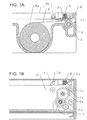
- FIG. 1 shows explanatory side views illustrating an embodiment of the present invention
- FIG. 1A is a sectional side view taken along line A-A shown in FIG. 2
- FIG. 1B is a sectional side view taken along line B-B shown in FIG. 2.
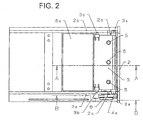
- FIG. 2 is a partially perspective plan view showing the whole apparatus.
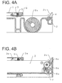
- FIGS. 3 and 4 depict operations of respective parts upon opening and closing a second frame 2;
- FIGS. 3A and 4A are sectional side views taken along line A-A shown in FIG. 2;
- FIGS. 3B and 4B are sectional side views taken along line B-B shown in FIG. 2.
- FIG. 5 is a perspective outview depicting the whole shape of a thermal printer according to the present invention.
- FIG. 6 is a conceptual view of a clamshell-type printer that has become widespread.
- FIGS. 1, 3, and 4 show main parts, as sectional views, of the thermal printer of the embodiment described here so as to depict its characteristic configuration simply.
- FIG. 1 shows explanatory side views illustrating the closed state of a first frame and a second frame and depicts the conditions during printing and standby.
- a thermal head 3 is pivotably supported to the first frame 1 by a head supporting shaft 3b provided in the thermal head 3.
- a biasing member 5, a compression coil spring in this embodiment, is disposed on the back face of the thermal head 3.
- a platen roller 4 is rotatably provided in the horizontal direction between sidewalls 2a and 2b of the second frame 2 shown in FIG. 2.
- the sidewall 2a is provided with a speed reducer 6 for driving the platen roller 4.
- the thermal head 3 biased by the biasing member 5 is in pressure contact with thermal recording paper (hereinafter referred to as "recording paper") 8 between the platen roller 4 and the thermal head 3.
- recording paper thermal recording paper
- Recording rolled paper 8a is used as the recording paper and is contained in the second frame.
- a rotary motor 7 is fixed to the second frame.
- a rotary motion of the motor 7 propagates from reduction gears 6a and 6b composing the speed reducer 6 to a platen driving gear 4a fixed to the platen roller 4 and thus the platen roller 4 is rotated clockwise in FIG. 1A to send the recording paper 8 in a paper ejection direction D.
- Printing is carried out by the passage of electric current through the thermal head 3 in synchronization with the rotation of the motor 7.
- the following description is directed to functions of a first cam 3a and a second cam 2c and the opening/closing operations of the first frame 1 and the second frame 2.
- FIG. 1 depicts a printing and printing-standby state, which is a so-called closed state of the first frame 1 and the second frame 2.
- Slight play is provided between the first cam 3a and the second cam 2c in the downward direction in FIG. 1.
- This is intended to exert the biasing force of the biasing member 5 for the pressure contact between the thermal head 3 and the recording paper 8, which is the original object.
- the first cam 3a and the second cam 2c are positioned with the play provided therebetween.
- the rotary driving force of the platen roller 4 pivotably supported to the second frame acts during printing in the direction in which the second frame 2 is closed with respect to the first frame 1, i.e. in the leftward direction in FIG. 1B by the friction between the recording paper 8 and the thermal head 3.
- the second frame is moved in the leftward direction in FIG. 1B and thus the precision in positioning the thermal head 3 and the platen roller 4 is not deteriorated due to the play.
- the first cam 3a follows the shape of the second cam to be guided in the upward direction in FIG. 3B.
- the thermal head 3 thereby opposes the biasing force of the biasing member 5 to compress the biasing member 5. This state is shown in FIG. 3A.
- the first cam 3a follows the shape of the second cam to be guided in the downward direction in FIG. 4B.
- the biasing member 5 that has been compressed as shown in FIG.
- the closing operation is opposite in procedure to the opening operation.
- the first cam 3a follows the shape of the second cam 2c again to be guided in the upward direction in FIG. 3B.
- the thermal head 3 thereby moves in the direction going away from the platen roller 4 as shown in FIG. 3A and thus the contact of the end face of the thermal head 3 with the platen roller 4 is avoided. This movement prevents the surface of the platen roller 4 from being damaged by the end face of the thermal head 3.
- a drawer-type thermal printer can be provided in which the thermal head pivotably supported to the first frame can be positioned with high precision with respect to the platen roller pivotably supported to the drawer-type second frame, a highly reliable opening/closing operation and a secure sense of operation can be achieved with a small number of parts, and the maintenance such as the loading of recording paper is facilitated.
Landscapes
- Common Mechanisms (AREA)
- Electronic Switches (AREA)
- Handling Of Sheets (AREA)
- Handling Of Continuous Sheets Of Paper (AREA)
- Unwinding Webs (AREA)
- Replacement Of Web Rolls (AREA)
- Advancing Webs (AREA)
Abstract
Description
Claims (4)
- A thermal printer comprising: a thermal head;
a first frame pivotably supporting the thermal head; a biasing member for biasing the thermal head to bring recording paper into pressure contact with the thermal head; a drawer-shaped second frame that can move in parallel to the first frame and contains recording paper; a platen roller rotatably supported to the second frame; a first cam provided in the thermal head; and a second cam formed in the second frame, characterized in that the first cam provided in the thermal head is guided by the second cam formed in the second frame, so that the platen roller pivotably supported to the second frame is positioned with respect to the thermal head. - The thermal printer according to claim 1, characterized in that a direction in which the recording paper moves on the thermal head during printing is substantially the same as that in which the second frame is drawn from the first frame.
- The thermal printer according to claim 1, characterized in that the second cam formed in the second frame guides the first cam provided in the thermal head in a direction opposing a biasing force of the biasing member at the instant of transition of the second frame and the first frame from a closed state to an opened state.
- The thermal printer according to claim 1, characterized in that the second cam formed in the second frame guides the first cam provided in the thermal head in a direction opposing a biasing force of the biasing member directly before transition of the second frame and the first frame from an opened state to a closed state.
Applications Claiming Priority (2)
| Application Number | Priority Date | Filing Date | Title |
|---|---|---|---|
| JP2000255912 | 2000-08-25 | ||
| JP2000255912A JP3908449B2 (en) | 2000-08-25 | 2000-08-25 | Drawer type line thermal printer |
Publications (2)
| Publication Number | Publication Date |
|---|---|
| EP1182042A2 true EP1182042A2 (en) | 2002-02-27 |
| EP1182042A3 EP1182042A3 (en) | 2002-11-13 |
Family
ID=18744617
Family Applications (1)
| Application Number | Title | Priority Date | Filing Date |
|---|---|---|---|
| EP01306805A Withdrawn EP1182042A3 (en) | 2000-08-25 | 2001-08-09 | Drawer-type line thermal printer |
Country Status (4)
| Country | Link |
|---|---|
| US (1) | US6469726B2 (en) |
| EP (1) | EP1182042A3 (en) |
| JP (1) | JP3908449B2 (en) |
| CN (1) | CN1340419A (en) |
Cited By (1)
| Publication number | Priority date | Publication date | Assignee | Title |
|---|---|---|---|---|
| EP1184190A3 (en) * | 2000-08-31 | 2003-03-19 | Alps Electric Co., Ltd. | Printer installable in small space |
Families Citing this family (5)
| Publication number | Priority date | Publication date | Assignee | Title |
|---|---|---|---|---|
| DE10215122B4 (en) * | 2002-04-05 | 2005-03-03 | Siemens Ag | Tachograph with a cuboidal housing and a printing device |
| DE10321233A1 (en) * | 2003-05-12 | 2004-12-09 | Siemens Ag | printer |
| DE10321225B4 (en) * | 2003-05-12 | 2005-03-03 | Siemens Ag | printer |
| JP6604741B2 (en) * | 2015-04-23 | 2019-11-13 | フクダ電子株式会社 | Medical measuring device |
| JP6904771B2 (en) * | 2017-04-26 | 2021-07-21 | セイコーインスツル株式会社 | Thermal printers and portable terminals |
Family Cites Families (1)
| Publication number | Priority date | Publication date | Assignee | Title |
|---|---|---|---|---|
| EP0183356B1 (en) * | 1984-10-02 | 1991-07-03 | Fujitsu Limited | Front-loading paper feed for a printer |
-
2000
- 2000-08-25 JP JP2000255912A patent/JP3908449B2/en not_active Expired - Fee Related
-
2001
- 2001-08-09 EP EP01306805A patent/EP1182042A3/en not_active Withdrawn
- 2001-08-17 US US09/931,724 patent/US6469726B2/en not_active Expired - Lifetime
- 2001-08-27 CN CN01125885.3A patent/CN1340419A/en active Pending
Cited By (1)
| Publication number | Priority date | Publication date | Assignee | Title |
|---|---|---|---|---|
| EP1184190A3 (en) * | 2000-08-31 | 2003-03-19 | Alps Electric Co., Ltd. | Printer installable in small space |
Also Published As
| Publication number | Publication date |
|---|---|
| US6469726B2 (en) | 2002-10-22 |
| US20020024584A1 (en) | 2002-02-28 |
| CN1340419A (en) | 2002-03-20 |
| JP3908449B2 (en) | 2007-04-25 |
| JP2002068545A (en) | 2002-03-08 |
| EP1182042A3 (en) | 2002-11-13 |
Similar Documents
| Publication | Publication Date | Title |
|---|---|---|
| CN100387436C (en) | Printer with cutter mechanism | |
| EP0894640A2 (en) | Printer apparatus | |
| US6469726B2 (en) | Drawer-type line thermal printer | |
| JP3116157B2 (en) | Line printer | |
| US5631690A (en) | Recording apparatus | |
| KR100385586B1 (en) | Clamshell device for printer | |
| JP4537541B2 (en) | Printer paper holder | |
| JP3617146B2 (en) | Printing device | |
| JPH04166373A (en) | facsimile | |
| JP7334488B2 (en) | printer | |
| JPH0224180A (en) | Pressure fixing device of printer head | |
| JP2007098731A (en) | Tape printer | |
| JPH05147285A (en) | Printer | |
| JP2000318257A (en) | Line thermal printer | |
| JP2980800B2 (en) | Printer | |
| JP3217797B2 (en) | Printing press for printing strip media | |
| JP3807479B2 (en) | Medium feeding device | |
| JP3659073B2 (en) | Paper feeder | |
| JPH0288275A (en) | Ink ribbon cassette fixing mechanism | |
| JP2000007197A (en) | Paper take-up device and printing device having the same | |
| JPH05300292A (en) | Fax machine | |
| US5231419A (en) | Apparatus for driving a platen roll and a thermal print head of a color video printer | |
| JPH05147314A (en) | Printer | |
| JP3704815B2 (en) | Decurling device in image forming apparatus | |
| KR950011884B1 (en) | Cassette Tape Ejector of Camcorder |
Legal Events
| Date | Code | Title | Description |
|---|---|---|---|
| PUAI | Public reference made under article 153(3) epc to a published international application that has entered the european phase |
Free format text: ORIGINAL CODE: 0009012 |
|
| AK | Designated contracting states |
Kind code of ref document: A2 Designated state(s): AT BE CH CY DE DK ES FI FR GB GR IE IT LI LU MC NL PT SE TR |
|
| AX | Request for extension of the european patent |
Free format text: AL;LT;LV;MK;RO;SI |
|
| PUAL | Search report despatched |
Free format text: ORIGINAL CODE: 0009013 |
|
| AK | Designated contracting states |
Kind code of ref document: A3 Designated state(s): AT BE CH CY DE DK ES FI FR GB GR IE IT LI LU MC NL PT SE TR |
|
| AX | Request for extension of the european patent |
Free format text: AL;LT;LV;MK;RO;SI |
|
| AKX | Designation fees paid | ||
| REG | Reference to a national code |
Ref country code: DE Ref legal event code: 8566 |
|
| STAA | Information on the status of an ep patent application or granted ep patent |
Free format text: STATUS: THE APPLICATION IS DEEMED TO BE WITHDRAWN |
|
| 18D | Application deemed to be withdrawn |
Effective date: 20030514 |