EP1181733B1 - Lithium ion batteries with improved resistance to sustained self-heating - Google Patents
Lithium ion batteries with improved resistance to sustained self-heating Download PDFInfo
- Publication number
- EP1181733B1 EP1181733B1 EP00916524A EP00916524A EP1181733B1 EP 1181733 B1 EP1181733 B1 EP 1181733B1 EP 00916524 A EP00916524 A EP 00916524A EP 00916524 A EP00916524 A EP 00916524A EP 1181733 B1 EP1181733 B1 EP 1181733B1
- Authority
- EP
- European Patent Office
- Prior art keywords
- anode
- lithium ion
- hours
- ion battery
- elemental metal
- Prior art date
- Legal status (The legal status is an assumption and is not a legal conclusion. Google has not performed a legal analysis and makes no representation as to the accuracy of the status listed.)
- Expired - Lifetime
Links
- 238000010438 heat treatment Methods 0.000 title claims abstract description 45
- 230000002459 sustained effect Effects 0.000 title claims abstract description 25
- 229910001416 lithium ion Inorganic materials 0.000 title claims abstract description 20
- HBBGRARXTFLTSG-UHFFFAOYSA-N Lithium ion Chemical compound [Li+] HBBGRARXTFLTSG-UHFFFAOYSA-N 0.000 title claims abstract description 19
- 229910052751 metal Inorganic materials 0.000 claims abstract description 31
- 239000002184 metal Substances 0.000 claims abstract description 31
- 239000000203 mixture Substances 0.000 claims abstract description 24
- 239000010409 thin film Substances 0.000 claims abstract description 21
- 229910052718 tin Inorganic materials 0.000 claims abstract description 12
- 239000003792 electrolyte Substances 0.000 claims abstract description 9
- 229910052782 aluminium Inorganic materials 0.000 claims abstract description 7
- 229910052710 silicon Inorganic materials 0.000 claims abstract description 7
- 229910052787 antimony Inorganic materials 0.000 claims abstract description 3
- 229910052797 bismuth Inorganic materials 0.000 claims abstract description 3
- 229910052793 cadmium Inorganic materials 0.000 claims abstract description 3
- 229910052738 indium Inorganic materials 0.000 claims abstract description 3
- 229910052725 zinc Inorganic materials 0.000 claims abstract description 3
- ATJFFYVFTNAWJD-UHFFFAOYSA-N Tin Chemical compound [Sn] ATJFFYVFTNAWJD-UHFFFAOYSA-N 0.000 claims description 11
- 239000011230 binding agent Substances 0.000 claims description 8
- 150000002739 metals Chemical class 0.000 claims description 7
- XAGFODPZIPBFFR-UHFFFAOYSA-N aluminium Chemical compound [Al] XAGFODPZIPBFFR-UHFFFAOYSA-N 0.000 claims description 6
- 239000010703 silicon Substances 0.000 claims description 6
- 229910052732 germanium Inorganic materials 0.000 claims description 3
- GNPVGFCGXDBREM-UHFFFAOYSA-N germanium atom Chemical compound [Ge] GNPVGFCGXDBREM-UHFFFAOYSA-N 0.000 claims description 3
- FYYHWMGAXLPEAU-UHFFFAOYSA-N Magnesium Chemical compound [Mg] FYYHWMGAXLPEAU-UHFFFAOYSA-N 0.000 claims description 2
- XUIMIQQOPSSXEZ-UHFFFAOYSA-N Silicon Chemical compound [Si] XUIMIQQOPSSXEZ-UHFFFAOYSA-N 0.000 claims description 2
- HCHKCACWOHOZIP-UHFFFAOYSA-N Zinc Chemical compound [Zn] HCHKCACWOHOZIP-UHFFFAOYSA-N 0.000 claims description 2
- WATWJIUSRGPENY-UHFFFAOYSA-N antimony atom Chemical compound [Sb] WATWJIUSRGPENY-UHFFFAOYSA-N 0.000 claims description 2
- JCXGWMGPZLAOME-UHFFFAOYSA-N bismuth atom Chemical compound [Bi] JCXGWMGPZLAOME-UHFFFAOYSA-N 0.000 claims description 2
- BDOSMKKIYDKNTQ-UHFFFAOYSA-N cadmium atom Chemical compound [Cd] BDOSMKKIYDKNTQ-UHFFFAOYSA-N 0.000 claims description 2
- APFVFJFRJDLVQX-UHFFFAOYSA-N indium atom Chemical compound [In] APFVFJFRJDLVQX-UHFFFAOYSA-N 0.000 claims description 2
- 229910052749 magnesium Inorganic materials 0.000 claims description 2
- 239000011777 magnesium Substances 0.000 claims description 2
- 239000011701 zinc Substances 0.000 claims description 2
- 229910052745 lead Inorganic materials 0.000 abstract 1
- XKRFYHLGVUSROY-UHFFFAOYSA-N Argon Chemical compound [Ar] XKRFYHLGVUSROY-UHFFFAOYSA-N 0.000 description 26
- 238000012360 testing method Methods 0.000 description 26
- OKTJSMMVPCPJKN-UHFFFAOYSA-N Carbon Chemical compound [C] OKTJSMMVPCPJKN-UHFFFAOYSA-N 0.000 description 23
- 239000002131 composite material Substances 0.000 description 15
- 229910002804 graphite Inorganic materials 0.000 description 15
- 239000010439 graphite Substances 0.000 description 15
- 230000000052 comparative effect Effects 0.000 description 14
- 238000006138 lithiation reaction Methods 0.000 description 14
- 229910052786 argon Inorganic materials 0.000 description 13
- 230000001351 cycling effect Effects 0.000 description 13
- RYGMFSIKBFXOCR-UHFFFAOYSA-N Copper Chemical compound [Cu] RYGMFSIKBFXOCR-UHFFFAOYSA-N 0.000 description 12
- 238000004544 sputter deposition Methods 0.000 description 12
- 239000000758 substrate Substances 0.000 description 11
- OIFBSDVPJOWBCH-UHFFFAOYSA-N Diethyl carbonate Chemical compound CCOC(=O)OCC OIFBSDVPJOWBCH-UHFFFAOYSA-N 0.000 description 10
- KMTRUDSVKNLOMY-UHFFFAOYSA-N Ethylene carbonate Chemical compound O=C1OCCO1 KMTRUDSVKNLOMY-UHFFFAOYSA-N 0.000 description 10
- 239000010408 film Substances 0.000 description 10
- 229910052799 carbon Inorganic materials 0.000 description 9
- 238000000151 deposition Methods 0.000 description 9
- 239000011889 copper foil Substances 0.000 description 8
- 230000008021 deposition Effects 0.000 description 8
- ZOKXTWBITQBERF-UHFFFAOYSA-N Molybdenum Chemical compound [Mo] ZOKXTWBITQBERF-UHFFFAOYSA-N 0.000 description 7
- 239000011149 active material Substances 0.000 description 7
- 238000007707 calorimetry Methods 0.000 description 7
- 238000000034 method Methods 0.000 description 7
- 229910052750 molybdenum Inorganic materials 0.000 description 7
- 239000011733 molybdenum Substances 0.000 description 7
- 229910001290 LiPF6 Inorganic materials 0.000 description 6
- WHXSMMKQMYFTQS-UHFFFAOYSA-N Lithium Chemical compound [Li] WHXSMMKQMYFTQS-UHFFFAOYSA-N 0.000 description 5
- 238000011067 equilibration Methods 0.000 description 5
- 229910052744 lithium Inorganic materials 0.000 description 5
- 239000000463 material Substances 0.000 description 5
- 238000002360 preparation method Methods 0.000 description 5
- 229910052802 copper Inorganic materials 0.000 description 4
- 239000010949 copper Substances 0.000 description 4
- 238000007599 discharging Methods 0.000 description 4
- 239000011244 liquid electrolyte Substances 0.000 description 4
- 229910032387 LiCoO2 Inorganic materials 0.000 description 3
- 239000002178 crystalline material Substances 0.000 description 3
- 230000020169 heat generation Effects 0.000 description 3
- WFKWXMTUELFFGS-UHFFFAOYSA-N tungsten Chemical compound [W] WFKWXMTUELFFGS-UHFFFAOYSA-N 0.000 description 3
- 229910052721 tungsten Inorganic materials 0.000 description 3
- 239000010937 tungsten Substances 0.000 description 3
- BQCIDUSAKPWEOX-UHFFFAOYSA-N 1,1-Difluoroethene Chemical compound FC(F)=C BQCIDUSAKPWEOX-UHFFFAOYSA-N 0.000 description 2
- YEJRWHAVMIAJKC-UHFFFAOYSA-N 4-Butyrolactone Chemical compound O=C1CCCO1 YEJRWHAVMIAJKC-UHFFFAOYSA-N 0.000 description 2
- XTHFKEDIFFGKHM-UHFFFAOYSA-N Dimethoxyethane Chemical compound COCCOC XTHFKEDIFFGKHM-UHFFFAOYSA-N 0.000 description 2
- XEEYBQQBJWHFJM-UHFFFAOYSA-N Iron Chemical compound [Fe] XEEYBQQBJWHFJM-UHFFFAOYSA-N 0.000 description 2
- 229920006370 Kynar Polymers 0.000 description 2
- PXHVJJICTQNCMI-UHFFFAOYSA-N Nickel Chemical compound [Ni] PXHVJJICTQNCMI-UHFFFAOYSA-N 0.000 description 2
- 239000004698 Polyethylene Substances 0.000 description 2
- WYURNTSHIVDZCO-UHFFFAOYSA-N Tetrahydrofuran Chemical compound C1CCOC1 WYURNTSHIVDZCO-UHFFFAOYSA-N 0.000 description 2
- 238000002441 X-ray diffraction Methods 0.000 description 2
- 239000002390 adhesive tape Substances 0.000 description 2
- 230000015572 biosynthetic process Effects 0.000 description 2
- 238000003490 calendering Methods 0.000 description 2
- 238000000576 coating method Methods 0.000 description 2
- 238000002524 electron diffraction data Methods 0.000 description 2
- 230000007613 environmental effect Effects 0.000 description 2
- 238000005530 etching Methods 0.000 description 2
- 238000011049 filling Methods 0.000 description 2
- 239000011888 foil Substances 0.000 description 2
- 239000000499 gel Substances 0.000 description 2
- 230000017525 heat dissipation Effects 0.000 description 2
- 239000011261 inert gas Substances 0.000 description 2
- 239000007788 liquid Substances 0.000 description 2
- -1 polyethylene Polymers 0.000 description 2
- 229920000573 polyethylene Polymers 0.000 description 2
- 229920000642 polymer Polymers 0.000 description 2
- 150000003839 salts Chemical class 0.000 description 2
- 238000007581 slurry coating method Methods 0.000 description 2
- 239000007787 solid Substances 0.000 description 2
- 239000007858 starting material Substances 0.000 description 2
- 229910052715 tantalum Inorganic materials 0.000 description 2
- GUVRBAGPIYLISA-UHFFFAOYSA-N tantalum atom Chemical compound [Ta] GUVRBAGPIYLISA-UHFFFAOYSA-N 0.000 description 2
- 238000013022 venting Methods 0.000 description 2
- 238000003466 welding Methods 0.000 description 2
- 238000004804 winding Methods 0.000 description 2
- WNXJIVFYUVYPPR-UHFFFAOYSA-N 1,3-dioxolane Chemical compound C1COCO1 WNXJIVFYUVYPPR-UHFFFAOYSA-N 0.000 description 1
- 229910003728 Li1.07Mn1.93O4 Inorganic materials 0.000 description 1
- 229910013562 LiCo0.2Ni0.8O2 Inorganic materials 0.000 description 1
- 229910052493 LiFePO4 Inorganic materials 0.000 description 1
- 229910013398 LiN(SO2CF2CF3)2 Inorganic materials 0.000 description 1
- 229910013406 LiN(SO2CF3)2 Inorganic materials 0.000 description 1
- 229910003005 LiNiO2 Inorganic materials 0.000 description 1
- 229910003817 NPF950 Inorganic materials 0.000 description 1
- 239000002033 PVDF binder Substances 0.000 description 1
- 229920003171 Poly (ethylene oxide) Polymers 0.000 description 1
- 239000004809 Teflon Substances 0.000 description 1
- 229920006362 Teflon® Polymers 0.000 description 1
- 102220634580 Vacuolar protein-sorting-associated protein 36_T10S_mutation Human genes 0.000 description 1
- 239000000853 adhesive Substances 0.000 description 1
- 230000001070 adhesive effect Effects 0.000 description 1
- PNEYBMLMFCGWSK-UHFFFAOYSA-N aluminium oxide Inorganic materials [O-2].[O-2].[O-2].[Al+3].[Al+3] PNEYBMLMFCGWSK-UHFFFAOYSA-N 0.000 description 1
- 229910021417 amorphous silicon Inorganic materials 0.000 description 1
- 238000000889 atomisation Methods 0.000 description 1
- 239000006229 carbon black Substances 0.000 description 1
- 230000001413 cellular effect Effects 0.000 description 1
- 238000006243 chemical reaction Methods 0.000 description 1
- 238000005229 chemical vapour deposition Methods 0.000 description 1
- 238000004140 cleaning Methods 0.000 description 1
- 239000011248 coating agent Substances 0.000 description 1
- 238000010276 construction Methods 0.000 description 1
- 239000000356 contaminant Substances 0.000 description 1
- 238000002788 crimping Methods 0.000 description 1
- 238000009792 diffusion process Methods 0.000 description 1
- 239000003085 diluting agent Substances 0.000 description 1
- IEJIGPNLZYLLBP-UHFFFAOYSA-N dimethyl carbonate Chemical compound COC(=O)OC IEJIGPNLZYLLBP-UHFFFAOYSA-N 0.000 description 1
- 238000001035 drying Methods 0.000 description 1
- 239000007772 electrode material Substances 0.000 description 1
- 238000004070 electrodeposition Methods 0.000 description 1
- 238000004880 explosion Methods 0.000 description 1
- 229910052500 inorganic mineral Inorganic materials 0.000 description 1
- 229910052742 iron Inorganic materials 0.000 description 1
- 235000015110 jellies Nutrition 0.000 description 1
- 239000008274 jelly Substances 0.000 description 1
- 229910001486 lithium perchlorate Inorganic materials 0.000 description 1
- MHCFAGZWMAWTNR-UHFFFAOYSA-M lithium perchlorate Chemical compound [Li+].[O-]Cl(=O)(=O)=O MHCFAGZWMAWTNR-UHFFFAOYSA-M 0.000 description 1
- 229910001496 lithium tetrafluoroborate Inorganic materials 0.000 description 1
- QSZMZKBZAYQGRS-UHFFFAOYSA-N lithium;bis(trifluoromethylsulfonyl)azanide Chemical compound [Li+].FC(F)(F)S(=O)(=O)[N-]S(=O)(=O)C(F)(F)F QSZMZKBZAYQGRS-UHFFFAOYSA-N 0.000 description 1
- 238000001755 magnetron sputter deposition Methods 0.000 description 1
- 238000005259 measurement Methods 0.000 description 1
- 238000002074 melt spinning Methods 0.000 description 1
- 239000002931 mesocarbon microbead Substances 0.000 description 1
- 229910052752 metalloid Inorganic materials 0.000 description 1
- 150000002738 metalloids Chemical class 0.000 description 1
- 239000011707 mineral Substances 0.000 description 1
- 229910052759 nickel Inorganic materials 0.000 description 1
- 229910052758 niobium Inorganic materials 0.000 description 1
- 239000010955 niobium Substances 0.000 description 1
- GUCVJGMIXFAOAE-UHFFFAOYSA-N niobium atom Chemical compound [Nb] GUCVJGMIXFAOAE-UHFFFAOYSA-N 0.000 description 1
- 239000003921 oil Substances 0.000 description 1
- 239000005486 organic electrolyte Substances 0.000 description 1
- 238000000643 oven drying Methods 0.000 description 1
- 229920002239 polyacrylonitrile Polymers 0.000 description 1
- 229920001451 polypropylene glycol Polymers 0.000 description 1
- 229920002981 polyvinylidene fluoride Polymers 0.000 description 1
- 239000000843 powder Substances 0.000 description 1
- RUOJZAUFBMNUDX-UHFFFAOYSA-N propylene carbonate Chemical compound CC1COC(=O)O1 RUOJZAUFBMNUDX-UHFFFAOYSA-N 0.000 description 1
- 238000005096 rolling process Methods 0.000 description 1
- 239000007784 solid electrolyte Substances 0.000 description 1
- 125000006850 spacer group Chemical group 0.000 description 1
- 238000007782 splat cooling Methods 0.000 description 1
- 239000007921 spray Substances 0.000 description 1
- 238000005477 sputtering target Methods 0.000 description 1
- 229910001220 stainless steel Inorganic materials 0.000 description 1
- 239000010935 stainless steel Substances 0.000 description 1
- 239000000126 substance Substances 0.000 description 1
- YLQBMQCUIZJEEH-UHFFFAOYSA-N tetrahydrofuran Natural products C=1C=COC=1 YLQBMQCUIZJEEH-UHFFFAOYSA-N 0.000 description 1
- 238000012546 transfer Methods 0.000 description 1
- 238000007738 vacuum evaporation Methods 0.000 description 1
Images


Classifications
-
- H—ELECTRICITY
- H01—ELECTRIC ELEMENTS
- H01M—PROCESSES OR MEANS, e.g. BATTERIES, FOR THE DIRECT CONVERSION OF CHEMICAL ENERGY INTO ELECTRICAL ENERGY
- H01M4/00—Electrodes
- H01M4/02—Electrodes composed of, or comprising, active material
- H01M4/36—Selection of substances as active materials, active masses, active liquids
- H01M4/38—Selection of substances as active materials, active masses, active liquids of elements or alloys
- H01M4/40—Alloys based on alkali metals
-
- H—ELECTRICITY
- H01—ELECTRIC ELEMENTS
- H01M—PROCESSES OR MEANS, e.g. BATTERIES, FOR THE DIRECT CONVERSION OF CHEMICAL ENERGY INTO ELECTRICAL ENERGY
- H01M10/00—Secondary cells; Manufacture thereof
- H01M10/05—Accumulators with non-aqueous electrolyte
- H01M10/052—Li-accumulators
-
- H—ELECTRICITY
- H01—ELECTRIC ELEMENTS
- H01M—PROCESSES OR MEANS, e.g. BATTERIES, FOR THE DIRECT CONVERSION OF CHEMICAL ENERGY INTO ELECTRICAL ENERGY
- H01M10/00—Secondary cells; Manufacture thereof
- H01M10/05—Accumulators with non-aqueous electrolyte
- H01M10/058—Construction or manufacture
-
- H—ELECTRICITY
- H01—ELECTRIC ELEMENTS
- H01M—PROCESSES OR MEANS, e.g. BATTERIES, FOR THE DIRECT CONVERSION OF CHEMICAL ENERGY INTO ELECTRICAL ENERGY
- H01M4/00—Electrodes
- H01M4/02—Electrodes composed of, or comprising, active material
- H01M4/13—Electrodes for accumulators with non-aqueous electrolyte, e.g. for lithium-accumulators; Processes of manufacture thereof
- H01M4/134—Electrodes based on metals, Si or alloys
-
- H—ELECTRICITY
- H01—ELECTRIC ELEMENTS
- H01M—PROCESSES OR MEANS, e.g. BATTERIES, FOR THE DIRECT CONVERSION OF CHEMICAL ENERGY INTO ELECTRICAL ENERGY
- H01M4/00—Electrodes
- H01M4/02—Electrodes composed of, or comprising, active material
- H01M4/36—Selection of substances as active materials, active masses, active liquids
- H01M4/38—Selection of substances as active materials, active masses, active liquids of elements or alloys
- H01M4/386—Silicon or alloys based on silicon
-
- H—ELECTRICITY
- H01—ELECTRIC ELEMENTS
- H01M—PROCESSES OR MEANS, e.g. BATTERIES, FOR THE DIRECT CONVERSION OF CHEMICAL ENERGY INTO ELECTRICAL ENERGY
- H01M4/00—Electrodes
- H01M4/02—Electrodes composed of, or comprising, active material
- H01M4/36—Selection of substances as active materials, active masses, active liquids
- H01M4/38—Selection of substances as active materials, active masses, active liquids of elements or alloys
- H01M4/387—Tin or alloys based on tin
-
- H—ELECTRICITY
- H01—ELECTRIC ELEMENTS
- H01M—PROCESSES OR MEANS, e.g. BATTERIES, FOR THE DIRECT CONVERSION OF CHEMICAL ENERGY INTO ELECTRICAL ENERGY
- H01M10/00—Secondary cells; Manufacture thereof
- H01M10/05—Accumulators with non-aqueous electrolyte
- H01M10/052—Li-accumulators
- H01M10/0525—Rocking-chair batteries, i.e. batteries with lithium insertion or intercalation in both electrodes; Lithium-ion batteries
-
- H—ELECTRICITY
- H01—ELECTRIC ELEMENTS
- H01M—PROCESSES OR MEANS, e.g. BATTERIES, FOR THE DIRECT CONVERSION OF CHEMICAL ENERGY INTO ELECTRICAL ENERGY
- H01M2200/00—Safety devices for primary or secondary batteries
-
- H—ELECTRICITY
- H01—ELECTRIC ELEMENTS
- H01M—PROCESSES OR MEANS, e.g. BATTERIES, FOR THE DIRECT CONVERSION OF CHEMICAL ENERGY INTO ELECTRICAL ENERGY
- H01M4/00—Electrodes
- H01M4/02—Electrodes composed of, or comprising, active material
- H01M4/36—Selection of substances as active materials, active masses, active liquids
- H01M4/38—Selection of substances as active materials, active masses, active liquids of elements or alloys
-
- H—ELECTRICITY
- H01—ELECTRIC ELEMENTS
- H01M—PROCESSES OR MEANS, e.g. BATTERIES, FOR THE DIRECT CONVERSION OF CHEMICAL ENERGY INTO ELECTRICAL ENERGY
- H01M6/00—Primary cells; Manufacture thereof
- H01M6/40—Printed batteries, e.g. thin film batteries
-
- Y—GENERAL TAGGING OF NEW TECHNOLOGICAL DEVELOPMENTS; GENERAL TAGGING OF CROSS-SECTIONAL TECHNOLOGIES SPANNING OVER SEVERAL SECTIONS OF THE IPC; TECHNICAL SUBJECTS COVERED BY FORMER USPC CROSS-REFERENCE ART COLLECTIONS [XRACs] AND DIGESTS
- Y02—TECHNOLOGIES OR APPLICATIONS FOR MITIGATION OR ADAPTATION AGAINST CLIMATE CHANGE
- Y02E—REDUCTION OF GREENHOUSE GAS [GHG] EMISSIONS, RELATED TO ENERGY GENERATION, TRANSMISSION OR DISTRIBUTION
- Y02E60/00—Enabling technologies; Technologies with a potential or indirect contribution to GHG emissions mitigation
- Y02E60/10—Energy storage using batteries
Definitions
- This invention relates to lithium ion batteries.
- Rechargeable batteries based upon lithium ion cells are attractive because they have inherently high capacities, high energies, and are operable over a useful temperature range.
- Such batteries feature a cathode, an anode, and a liquid or solid organic electrolyte.
- One problem with such batteries is a tendency for the battery to self-heat at elevated temperatures. Self heating results when exothermic reactions within the battery components are activated. Sustained self-heating occurs when the rate of heat generation within the battery exceeds the rate of heat dissipation from the battery surface to the surrounding area. Sustained self-heating can lead to thermal run-away, resulting in venting, flaring, and, in some cases, explosion.
- the rate of heat generation increases as the capacity and energy of the battery increase. Accordingly, the problem of sustained self-heating becomes increasingly important as the battery industry seeks to maximize the capacity and energy of lithium ion batteries.
- the sustained self-heating problem also limits the ultimate size of the battery. This is because surface area grows as the square of the battery dimensions, whereas volume grows as the cube of the battery dimensions. Accordingly, at a certain size, the rate of heat generation within the battery exceeds the rate of heat dissipation from the battery surface, leading to sustained self-heating at elevated temperatures.
- the invention features a lithium ion battery that includes: (a) a cathode; (b) an anode in the form of a thin film that is free of binders and (c) an electrolyte separating the anode and the cathode. Both solid and liquid electrolytes can be used.
- the battery has a capacity of at least 600 milliamp-hours, a specific energy of at least 100 watt-hours/kg, and a volumetric energy of at least 250 watt-hours/liter.
- the anode When lithiated, the anode does not exhibit sustained self-heating at temperatures up to about 100°C, preferably at temperatures up to about 150°C, and more preferably at temperatures up to about 170°C, as determined using Accelerated Rate Calorimetry described infra. Even more preferred are anodes that do not exhibit sustained self-heating at temperatures up to about 200°C.
- the anode includes an electrochemically active elemental metal.
- a "thin film anode” refers to an anode in the form of a continuous film that is free of binders such as polymeric binders. Accordingly, such anodes are distinguishable from composite anodes prepared by admixing an electrochemically active powder with a conductive diluent such as graphite or carbon black, and a binder.
- An “electrochemically active elemental metal” is an elemental metal that reacts with lithium under conditions typically encountered during charging and discharging in a lithium battery.
- An “electrochemically inactive elemental metal” is an elemental metal that does not react with lithium under those conditions.
- Elemental metal refers to both metals and to metalloids such as silicon and germanium.
- a “liquid electrolyte” includes both liquids and liquid-swollen gels.
- Examples of preferred electrochemically active elemental metals include aluminum, silicon, tin, antimony, lead, germanium, magnesium, zinc, cadmium, bismuth, and indium.
- the anode may further include one or more electrochemically inactive elemental metals. Examples include molybdenum, niobium, tungsten, tantalum, iron, and copper.
- One useful anode features a combination of tin and molybdenum.
- Other useful anodes include silicon, alone or in combination with aluminum or tin.
- the anode has a specific capacity of at least 100 milliamp-hours/g (preferably at least 300 milliamp-hours/g) and a volumetric capacity of at least 600 milliamp-hours/cm3. Several different anode compositions may be used.
- the anode consists essentially of a plurality of electrochemically active elemental metals, and has a microstructure that includes these elemental metals in the form of a mixture that is essentially free of domains measuring greater than about 1000 angstroms.
- a "domain” is a region that consists essentially af a single electrochemically active elemental metal.
- the domain may be crystalline (i.e., it gives rise to a discernible electron or x-ray diffraction pattern characteristic of a crystalline material) or non-crystalline.
- the size of the domain refers to the longest dimension of the domain. Examples of such anodes are described in Turner, U.S.S.N. 09/113,385 entitled "Electrode Material and Compositions Including Same," filed July 10,1998 and assigned to the same assignee as the present application.
- a second useful anode composition is one in which the anode includes (a) an electrochemically active elemental metal and (b) an electrochemically inactive elemental metal.
- the microstructure of the anode is characterized by the presence of crystalline regions after a battery incorporating the anode has been cycled through one full charge-discharge cycle.
- These crystalline regions which are characterized by a discernible x-ray diffraction pattern characteristic of a crystalline material, preferably have at least one dimension that is no greater than about 500 angstroms after the battery has been cycled through one full charge-discharge cycle, and do not substantially increase after a total of at least 10 cycles.
- these crystalline regions are preferably separated by regions that include the electrochemically active elemental metal and the electrochemically inactive elemental metal in which the relative proportions of the electrochemically active elemental metal and the electrochemically inactive elemental metal vary throughout the thickness direction of the composition (i.e., the direction perpendicular to the substrate on which the thin film is deposited). These latter regions do not exhibit an electron diffraction pattern characteristic of a crystalline material.
- the battery also preferably exhibits good high temperature properties. Specifically, after being subjected to one full charge-discharge cycle at 80°C, the capacity fade is no greater than 2% per cycle, preferably no greater than 1% per cycle, and, even more preferably, no more than 0.5% per cycle.
- the invention provides lithium ion batteries that exhibit high capacity and energy, yet exhibit improved resistance to sustained self-heating relative to batteries featuring graphite- or carbon-containing composite electrodes.
- Conventional battery designs can be used, thereby eliminating the need for elaborate mechanical measures.
- even batteries having relatively large dimensions can be manufactured.
- the batteries also retain their superior performance (as measured by the extent of capacity fade) at high temperatures.
- batteries could be used as a power supply for a number of devices that operate using energy from a power supply. Examples includes vehicles such a automobiles, trucks, and bicycles.
- the batteries also could find numerous applications in aircraft. For example, they could be used as an engine starter for the aircraft. They could also be used to supply power to on-board computers and telephones. Other potential applications include power supplies for satellites, telecommunications devices such as cellular telephones, and portable computers.
- the invention features high capacity, high energy lithium ion batteries that include a cathode, a thin film anode, and an electrolyte separating the cathode and anode in which the anode resists sustained self-heating at temperatures up to about 100°C, preferably up to about 150°C, more preferably up to about 170°C, and even more preferably up to about 200°C, determined using Accelerated Rate Calorimetry described below.
- These films exhibit specific and/or volumetric capacities in excess of the values associated with typical composite graphite anodes, and preferably include at least one electrochemically active elemental metal. They may be prepared according to a variety of methods, including sputtering, chemical vapor deposition, vacuum evaporation, melt spinning, splat cooling, rolling, electrodeposition, and spray atomization.
- the electrolyte is provided with a lithium electrolyte salt.
- suitable salts include LiPF6, LiBF4, LiClO4, LiN(SO2CF3)2, and LiN(SO2CF2CF3)2.
- suitable liquid electrolytes include ethylene carbonate, dimethyl carbonate, diethyl carbonate, propylene carbonate, gamma-butyrolactone, tetrahydrofuran, 1,2-dimethoxyethane, dioxolane, and combinations thereof
- a polymer such as polyethylene oxide, polypropylene oxide, polyacrylonitrile, or polyvinylidene fluoride to produce a swollen gel.
- a dry, solid polymer may be used as the electrolyte.
- cathode compositions examples include LiCoO2, LiCo0.2Ni0.8O2, Li1.07Mn1.93O4, LiNiO2, and LiFePO4.
- Anodes in the form of thin films were prepared by sequential sputtering using either a modified Parkin-Elmer Randex Model 2400-8SA Sputtering System (Examples 2 and 4) or a Mill Lane High Vacuum System (P4) with an 457.2 mm (18 inch) wide web handling system (Examples 1,3, and 5).
- the original 8 inch diameter rf sputter sources were replaced with 152.4 mm (6 inch) diameter dc magnetron sputtering sources commercially available from Materials Science of San Diego, CA.
- the sputtering sources were powered using Advanced Energy Model MDX-10 dc sputtering power supplies operating in constant current mode.
- the turntable drive unit was replaced with a stepper motor to improve rotation speed and control.
- the system was pumped with an untrapped oil diffusion pump backed by a conventional rotary vane pump.
- Sputtering was performed at argon pressures in the range of 400-4000 mPa (3-30 mTorr).
- the sputtering sources were started up using a mechanical shutter between the sources and the copper substrate. This removed contaminants from the source surface without depositing them on the substrate surface.
- a "pre-layer” made of a single material of known identity was deposited onto the substrate. The purpose of the pro-layer was to insure good adhesion between the substrate and the sputter deposited film.
- both sources were started up at pro-determined current levels and deposition initiated. After a suitable deposition time, one or both sources were turned off. A.''post-layer" of a single material of known identity was then deposited, after which the system was vented and the sample removed.
- the copper foil was exposed off-line at a rate of 10 mm/sec (2 ft./min.) to an oxygen-doped rf argon plasma in a commercial PlasmaTherm system operated at 1 kW and 27 Pa (200mTorr).
- a segment of the film was positioned using double-sided adhesive tape (as described above) on a rotating drum within the Mill Lane system such that it faced three opposing sputtering targets.
- the drum was set to rotate at 38 rpm.
- Deposition commenced at a pressure of 1400 mPa (12 mTorr).
- a pre-layer of tantalum (about 500 angstroms thick) was deposited to improve adhesion between the film and the substrate. This was followed by deposition of the film components using one or two targets operating at a power level between 0.2 kW to 5 kW for a suitable period of time. Finally, a post-layer of a single material of known identity was deposited.
- Example 1 In the case of pre-layer deposition, a power level of 2 kW was used in Examples 1, 3, and 5, while a current level of 1.5 A was used in Example 2.
- Example 4 did not contain a pre-layer.
- composition A contained 87 wt.% MCMB 10-28 graphite (from Alumina), 3 wt.% Shawinigan Black (from Chevron), and 10 wt.% binder ("301F” from Elf Atochem).
- Composition B contained 91 wt.% SFG-44 graphite (from TIMCAL America, Inc.), 3 wt.% Super P carbon (from MMM Carbon), and 6 wt.% binder ("Kynar 461" from Elf Atochem).
- Strips measuring 123 mm by 26 mm were lithiated in a flat cell by electrochemical reduction to 0.008V vs. Li.
- the flat cell consisted of two halves sealed together by means of an o-ring gasket to form a flat cavity.
- a metallic lithium foil having a thickness of 150 micrometers (from Cyprus Foote Mineral) that served as both a counter and reference electrode
- two microporous polyethylene films each having a thickness of 25 micrometers, that served as separators
- the anode component in the form of either a sputtered thin film or a graphite composite composition, that served as the working electrode. Contact to the working and counter electrodes was provided through the two cell halves.
- the cell was assembled in a dry room, after which it was transferred and cycled in an argon-filled dry box using a Maccor Cell Cycler to lithiate the working electrode. After cycling, the cells were regularly left at open circuit voltage for a minimum of 2 hours before the cell was opened in the glove box and the lithiated working electrode removed and left to dry.
- ARC Accelerated Rate Calorimetry
- the instrumentation used for the testing was an ARC-2000 accelerated calorimeter from Columbia Scientific Environmental Instrumentation of Austin, TX.
- the ARC instrument is an adiabatic calorimeter that correlates the calorimeter temperature with the-sample temperature. If the sample self-heats, the calorimeter temperature increases so that there is no heat flow between the sample and the calorimeter.
- the resulting measurement is in the form of a graph depicting the onset and rate of sustained self-heating as a function of temperature.
- lithiated samples were cut in an argon-filled glove box and placed in a 304SS tube measuring 38 mm long with an outer diameter of 6.35 mm (0.25 inch). In some cases, where adhesion was poor, the lithiated coatings were flaked off the copper backing before being added to the tube.
- one end of the tube Prior to filling, one end of the tube was crimped and tungsten inert gas welded to provide an hermetic seal using a Miller model Maxstar 91 welder equipped with a high frequency arc starter model Snap Star II The sample weight was recorded, after which a measured amount of electrolyte was added to the tube. Next, the other end of the tube was crimped and seated by tungsten inert gas welding. During the latter operation, the tube was placed between jaws capable of transferring any heat from the welding away from the contents of the tube.
- the sample tube was placed in the ARC calorimeter.
- the calorimeter was operated in the Heat-Wait-Search Mode. It was initially programmed to heat the calorimeter to 40°C at a rate of 10°C/min. Heating was followed by a 15 minute wait period to establish temperature stability. At the end of the wait period, a 20 minute search period began.
- any self-heating of the sample was monitored. If the self-heating measured above a threshold level of 0.03°C/min., it was matched by the calorimeter to establish adiabatic conditions. If no self-heating was observed, the calorimeter temperature was increased 10°C and the process repeated. Testing was terminated whenever the self-heating rate exceeded 15°C/min. or the calorimeter temperature reached 230°C.
- Anode samples were slit into strips measuring 58 mm by 680 mm, with a 10 mm uncoated area at one end.
- a current collecting nickel tab was ultrasonically welded to the uncoated end.
- a cathode was prepared by slurry coating a composition containing 91 wt.% LiCoO2 ("CellSeed 10" from Nippon Chemical Co.), 2.5 wt.% KS-6 graphite (from TIMCAL America), 2.5 wt.% Super P carbon (from MMM Carbon), and 4 wt.% binder ("Kynar 461" from Elf Atochem) on both sides of a 20 micrometer thick aluminum foil, followed by drying and calendering to yield a film having a thickness of 90 micrometers.
- the resulting article was then slit into strips measuring 56 mm wide by 650 mm long, with a 30 mm uncoated area at one end. A current collecting aluminum tab was ultrasonically welded to the uncoated end.
- the resulting anode and cathode were wound in a cylindrical jelly roll with a 60 mm wide, 25 micrometer thick microporous polyethylene separator ("SETELA E25" from Mobil Chemical Corp.) placed between the anode and the cathode.
- the winding was performed on a laboratory winder from Toyo Systems. After winding, the resulting roll was placed in a 18650 battery cell can, and the can was filled with 4-5 grams of a 1 molal solution of LiPF6 in a 1:1 v/v mixture of ethylene carbonate and diethyl carbonate using a vacuum electrolyte filling system (also from Toyo Systems). The can was then closed in standard fashion by crimping using an insulating ring, spacer, rupture disc, and stainless steel header.
- Hot Box Testing was used to evaluate the self-heating behavior of batteries incorporating thin film anodes and carbon (or graphite) composite anodes in their lithiated state. The testing was performed on charged 18650 cylindrical wound batteries (prepared as described above) using a Tenney Model T10S Environmental Test Chamber (from Lunaire Limited of Wiliiamsport, PA) preheated to the test temperature.
- the batteries Prior to testing, the batteries were cycled for 6 to 8 cycles at 23°C using a Maccor cell cycler.
- the batteries in a charged state were then placed horizontally in the oven of the test chamber in a Teflon holder with spring loaded metallic contacts to the battery top and bottom. The contact area was kept small to minimize heat transfer.
- An adhesive microprobe type K thermocouple with thin leads was placed around the battery body to monitor the temperature of the battery surface. Another thermocouple was placed less than 2 cm away from the top of the battery to monitor the oven temperature.
- the oven and battery temperature were recorded using a Maccor cell cycler.
- the general battery performance was also monitored visually through a window in the oven door or via a video camera.
- This comparative example illustrates the self-heating behavior of a composite graphite anode prepared using Composition A.
- a strip was lithiated to a level of 362 milliamp-hours/g by cycling a total of one and a half cycles (ending with a lithiation step) between 0.008V and 1.2V. The samples were then allowed to equilibrate at open circuit voltage.
- Samples for ARC testing were prepared in an argon-filled glove box by adding 172 mg of a lithiated strip (corresponding to 74 mg of active material and a lithiation level of 27 milliamp-hours) to an ARC sample tube. 100 mg of a 1 molal solution of LiPF6 in a 1:1 v/v mixture of ethylene carbonate and diethyl carbonate were then added and the sample tube sealed.
- ARC curve recorded from 40°C to 230°C from this sample is shown in Fig. 1.
- onset temperature of sustained self-heating was 90°C.
- This comparative example illustrates the self-heating behavior of a composite graphite anode prepared using Composition B.
- a strip was lithiated to a level of 430 milliamp-hours/g by cycling a total of one and a half cycles (ending with a lithiation step) between 0.008V and 1.2V. The samples were then allowed to equilibrate at open circuit voltage.
- Samples for ARC testing were then prepared in an argon-filled glove box by flaking the coating off the copper foil backing and adding 106 mg of the flakes (corresponding to 63 mg of active material and a lithiation level of 27 milliamp-hours) to an ARC sample tube. 100 mg of a 1 molal solution ofLiPF6 in a 1:1 v/v mixture of ethylene carbonate and diethyl carbonate were then added and the sample tube sealed.
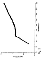
- ARC curve recorded from 40°C to 230°C from this sample is shown in Fig. 2.
- onset temperature of sustained self-heating was 80°C.
- This example illustrates the self-heating behavior of a thin film anode containing 54 wt.% tin and 46 wt.% molybdenum on a 25 micrometer thick copper foil.
- a strip was lithiated to a level of 353 milliamp-hours/g by cycling a total of one and a half cycles (ending with a lithiation step) between 0.008V and 1.2V, followed by equilibration at open cell voltage for at least 2 hours.
- Samples for ARC testing were then prepared in an argon-filled glove box by adding 265 mg of the sample (corresponding to 73 mg of active material and a lithiation level of 26 milliamp-hours) to an ARC sample tube. 100 mg of a 1 molal solution ofLiPF6 in 1:1 v/v ethylene carbonate and diethyl carbonate were then added and the sample tube sealed.
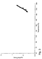
- ARC curve recorded from 40°C to 230°C from this sample is shown in Fig. 3.
- onset temperature of sustained self-heating was 200°C.
- This example illustrates the self-heating behavior of a thin film anode containing 64 wt.% aluminum and 36 wt.% silicon on a 25 micrometer thick copper foil.
- a strip was lithiated to a level of 1443 milliamp-hours/g by cycling a total of one and a half cycles (ending with a lithiation step) between 0.008V and 0.9V, followed by equilibration at open cell voltage for at least 2 hours.
- Samples for ARC testing were then prepared in an argon-filled glove box by adding 84 mg of sample flakes (corresponding to 19 mg of active material and a lithiation level of 27 milliamp-hours) to an ARC sample tube. 100 mg of a 1 molal solution of LiPF6 in 1:1 v/v ethylene carbonate and diethyl carbonate were then added and the sample tube sealed.
- the ARC curve for this sample recorded from 40°C to 230°C, showed the onset temperature of sustained self-heating to be 190°C.
- This example illustrates the self-heating behavior of a thin film anode containing 74 wt.% tin and 26 wt.% silicon on a 25 micrometer thick copper foil.
- a strip was lithiated to a level of 1864 milliamp-hours/g by cycling a total of one and a half cycles (ending with a lithiation step) between 0.008V and 0.9V, followed by equilibration at open cell voltage for at least 2 hours.
- Samples for ARC testing were then prepared in an argon-filled glove box by adding 51 mg of the sample (corresponding to 14.5 mg of active material and a lithiation level of 27 milliamp-hours) to an ARC sample tube. 100 mg of a 1 molal solution ofLiPF6 in 1:1 v/v ethylene carbonate and diethyl carbonate were then added and the sample tube sealed.
- the ARC curve for this sample recorded from 40°C to 230°C, showed the onset temperature of sustained self-heating to be 180°C.
- This example illustrates the self-heating behavior of a thin film anode containing 100 wt.% amorphous silicon on a 25 micrometer thick copper foil.
- a strip was lithiated to a level of 3360 milliamp-hours/g by cycling a total of one and a half cycles between 0.008V and 0.9V, followed by equilibration at open cell voltage for at least 2 hours.
- Samples for ARC testing were then prepared in an argon-filled glove box by adding 65 mg of sample flakes (corresponding to 8.0 mg of active material and a lithiation level of 27 milliamp-hours) to an ARC sample tube. 100 mg of a 1 molal solution of LiPF6 in 1:1 v/v ethylene carbonate and diethyl carbonate were then added and the sample tube sealed.
- the ARC curve for this sample recorded from 40°C to 230°C, showed the onset temperature of sustained self-heating to be 190°C.
- This example illustrates the self-heating behavior of a thin film anode containing 100 wt.% tin on a 25 micrometer thick copper foil.
- a strip was lithiated to a level of 725 milliamp-hours/g by cycling a total of one and a half cycles (ending with a lithiation step) between 0.008V and 0.9V, followed by equilibration at open cell voltage for at least 2 hours.
- Samples for ARC testing were then prepared in an argon-filled glove box by adding 134 mg of the sample (corresponding to 26.9 mg of active material and a lithiation level of 27 milliamp-hours) to an ARC sample tube. 100 mg of a 1 molal solution ofLiPF6 in 1:1 v/v ethylene carbonate and diethyl carbonate were then added and the sample tube sealed.
- the ARC curve for this sample recorded from 40°C to 230°C, showed the onset temperature of sustained self heating to be 200°C.
- a commercial 18650 lithium ion battery was obtained from a Sony NPF950 camcorder battery pack.
- the battery had a volume of 16.54 cm3 and a mass of 40.5 g.
- the battery as received from the factory, was cycled for eight cycles to establish performance according to a standard cycling protocol for this type of battery.
- the battery was charged to 4.2V using a constant current of 0.28 amps with trickle charge to a current limit of 0.03 amps, followed by discharging to 2.75V using a constant current of 0.28 amps. Based upon the cycling results, the battery's capacity was determined to be 1372 milliamp-hours and 5074 milliwatt-hours, corresponding to a battery energy density of 125 watt-hours/kg and 306 watt-hours/liter.
- This example demonstrates the preparation of a battery having a higher capacity than the battery described in Comparative Example C, yet which does not exhibit sustained self heating or thermal run-away at temperatures up to at least about 130°C.
- An 18650 battery was prepared as described above using a thin film anode containing 54 wt.% tin and 46 wt.% molybdenum, and a LiCoO2 composite cathode.
- the active anode weight was 6.35g
- the active cathode weight was 15.71g
- the active battery area was 694 cm2.
- the total battery weight was 50.78g and the total battery volume was 16.54 cm2.
- the battery was cycled for four cycles between 4.2V and 2.0V by charging the battery to 4.2V using a constant current of 0.3 amps with trickle charge to a current limit of 0.03 amps, followed by discharging to 2V at a constant current of 0.3 amps with a trickle charge to 0.03 amps.
- the charge capacity was limited to 1700 milliamp-hours, corresponding to 5746 milliwatt-hours/liter. This corresponds to a battery energy density of 113 watt-hours/kg and 347 watt-hours/liter.
- Comparative Example C The procedure of Comparative Example C was repeated except that the battery was subjected to Hot Box testing at 150°C. The recorded battery temperature is shown in Fig. 5. After approximately 30 minutes, the battery exhibited thermal run-away, resulting in venting and flaring.
- Example 6 The procedure of Example 6 was followed except that the active anode weight was 6.18g and the active cathode weight was 15.78g. The total battery weight was 50.69g.
- the battery was cycled for four cycles between 4.2V and 2.0V by charging the battery to 4.2V using a constant current of 0.3 amps with trickle charge to a current limit of 0.03 amps, followed by discharging to 2V at a constant current of 0.3 amps with a trickle charge to 0.03 amps.
- the charge capacity was limited to 1740 milliamp-hours, corresponding to 5846 milliwatt-hours/liter. This corresponds to a battery energy density of 115 watt-hours/kg and 353 watt-hours/liter.
Landscapes
- Chemical & Material Sciences (AREA)
- Chemical Kinetics & Catalysis (AREA)
- Electrochemistry (AREA)
- General Chemical & Material Sciences (AREA)
- Engineering & Computer Science (AREA)
- Manufacturing & Machinery (AREA)
- Materials Engineering (AREA)
- Secondary Cells (AREA)
- Battery Electrode And Active Subsutance (AREA)
Abstract
Description
- This invention relates to lithium ion batteries.
- Rechargeable batteries based upon lithium ion cells are attractive because they have inherently high capacities, high energies, and are operable over a useful temperature range. Such batteries feature a cathode, an anode, and a liquid or solid organic electrolyte. One problem with such batteries, however, is a tendency for the battery to self-heat at elevated temperatures. Self heating results when exothermic reactions within the battery components are activated. Sustained self-heating occurs when the rate of heat generation within the battery exceeds the rate of heat dissipation from the battery surface to the surrounding area. Sustained self-heating can lead to thermal run-away, resulting in venting, flaring, and, in some cases, explosion.
- The rate of heat generation increases as the capacity and energy of the battery increase. Accordingly, the problem of sustained self-heating becomes increasingly important as the battery industry seeks to maximize the capacity and energy of lithium ion batteries.
- The sustained self-heating problem also limits the ultimate size of the battery. This is because surface area grows as the square of the battery dimensions, whereas volume grows as the cube of the battery dimensions. Accordingly, at a certain size, the rate of heat generation within the battery exceeds the rate of heat dissipation from the battery surface, leading to sustained self-heating at elevated temperatures.
- In general, the invention features a lithium ion battery that includes: (a) a cathode; (b) an anode in the form of a thin film that is free of binders and (c) an electrolyte separating the anode and the cathode. Both solid and liquid electrolytes can be used. The battery has a capacity of at least 600 milliamp-hours, a specific energy of at least 100 watt-hours/kg, and a volumetric energy of at least 250 watt-hours/liter. When lithiated, the anode does not exhibit sustained self-heating at temperatures up to about 100°C, preferably at temperatures up to about 150°C, and more preferably at temperatures up to about 170°C, as determined using Accelerated Rate Calorimetry described infra. Even more preferred are anodes that do not exhibit sustained self-heating at temperatures up to about 200°C. Preferably, the anode includes an electrochemically active elemental metal.
- A "thin film anode" refers to an anode in the form of a continuous film that is free of binders such as polymeric binders. Accordingly, such anodes are distinguishable from composite anodes prepared by admixing an electrochemically active powder with a conductive diluent such as graphite or carbon black, and a binder.
- An "electrochemically active elemental metal" is an elemental metal that reacts with lithium under conditions typically encountered during charging and discharging in a lithium battery. An "electrochemically inactive elemental metal" is an elemental metal that does not react with lithium under those conditions.
- "Elemental metal" refers to both metals and to metalloids such as silicon and germanium.
- A "liquid electrolyte" includes both liquids and liquid-swollen gels.
- Examples of preferred electrochemically active elemental metals include aluminum, silicon, tin, antimony, lead, germanium, magnesium, zinc, cadmium, bismuth, and indium. The anode may further include one or more electrochemically inactive elemental metals. Examples include molybdenum, niobium, tungsten, tantalum, iron, and copper. One useful anode features a combination of tin and molybdenum. Other useful anodes include silicon, alone or in combination with aluminum or tin.
- The anode has a specific capacity of at least 100 milliamp-hours/g (preferably at least 300 milliamp-hours/g) and a volumetric capacity of at least 600 milliamp-hours/cm3. Several different anode compositions may be used.
- According to one embodiment, the anode consists essentially of a plurality of electrochemically active elemental metals, and has a microstructure that includes these elemental metals in the form of a mixture that is essentially free of domains measuring greater than about 1000 angstroms. A "domain" is a region that consists essentially af a single electrochemically active elemental metal. The domain may be crystalline (i.e., it gives rise to a discernible electron or x-ray diffraction pattern characteristic of a crystalline material) or non-crystalline. The size of the domain refers to the longest dimension of the domain. Examples of such anodes are described in Turner, U.S.S.N. 09/113,385 entitled "Electrode Material and Compositions Including Same," filed July 10,1998 and assigned to the same assignee as the present application.
- A second useful anode composition is one in which the anode includes (a) an electrochemically active elemental metal and (b) an electrochemically inactive elemental metal. The microstructure of the anode is characterized by the presence of crystalline regions after a battery incorporating the anode has been cycled through one full charge-discharge cycle.
- These crystalline regions, which are characterized by a discernible x-ray diffraction pattern characteristic of a crystalline material, preferably have at least one dimension that is no greater than about 500 angstroms after the battery has been cycled through one full charge-discharge cycle, and do not substantially increase after a total of at least 10 cycles. Moreover, these crystalline regions are preferably separated by regions that include the electrochemically active elemental metal and the electrochemically inactive elemental metal in which the relative proportions of the electrochemically active elemental metal and the electrochemically inactive elemental metal vary throughout the thickness direction of the composition (i.e., the direction perpendicular to the substrate on which the thin film is deposited). These latter regions do not exhibit an electron diffraction pattern characteristic of a crystalline material. They may be present prior to cycling, after cycling, or both before and after. cycling. Examples of such anodes. are described in Turner et al., U.S.S.N. 09/048,407 entitled "Electrode Compositions," filed March 26, 1998 and assigned to the same assignee as the present application.
- The battery also preferably exhibits good high temperature properties. Specifically, after being subjected to one full charge-discharge cycle at 80°C, the capacity fade is no greater than 2% per cycle, preferably no greater than 1% per cycle, and, even more preferably, no more than 0.5% per cycle.
- The invention provides lithium ion batteries that exhibit high capacity and energy, yet exhibit improved resistance to sustained self-heating relative to batteries featuring graphite- or carbon-containing composite electrodes. Conventional battery designs can be used, thereby eliminating the need for elaborate mechanical measures. Moreover, even batteries having relatively large dimensions can be manufactured. The batteries also retain their superior performance (as measured by the extent of capacity fade) at high temperatures.
- These batteries could be used as a power supply for a number of devices that operate using energy from a power supply. Examples includes vehicles such a automobiles, trucks, and bicycles. The batteries also could find numerous applications in aircraft. For example, they could be used as an engine starter for the aircraft. They could also be used to supply power to on-board computers and telephones. Other potential applications include power supplies for satellites, telecommunications devices such as cellular telephones, and portable computers.
- Other features and advantages of the invention will be apparent from the following description of the preferred embodiments thereof, and from the claims.
-
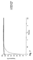
- Fig. 1 illustrates the onset temperature for sustained self-heating, and the self-heating rate as a function of temperature, for the composite graphite anode described in Comparative Example A, measured using Accelerated Rate Calorimetry.
- Fig. 2 illustrates the onset temperature for sustained self-heating, and the self-heating rate as a function of temperature, for the composite graphite anode described in Comparative Example B, measured using Accelerated Rate Calorimetry.
- Fig. 3 illustrates the onset temperature for sustained self-heating, and the self-heating rate as a function of temperature, for the tin/molybdenum thin film anode described in Example 1, measured using Accelerated Rate Calorimetry.
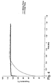
- Fig. 4 illustrates the oven temperature and outside battery temperature reached during Hot Box testing of the battery described in Comparative Example C incorporating a composite carbon anode.
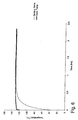
- Fig. 5 illustrates the oven temperature and outside battery temperature reached during Hot Box testing of the battery described in Comparative Example D incorporating a composite carbon anode.
- Fig. 6 illustrates the oven temperature and outside battery temperature reached during Hot Box testing of the battery described in Example 6 incorporating a tin/molybdenum thin film anode.
- Fig. 7 illustrates the oven temperature and outside battery temperature reached during Hot Box testing of the battery described in Example 7 incorporating a tin/molybdenum thin film anode.
-
- The invention features high capacity, high energy lithium ion batteries that include a cathode, a thin film anode, and an electrolyte separating the cathode and anode in which the anode resists sustained self-heating at temperatures up to about 100°C, preferably up to about 150°C, more preferably up to about 170°C, and even more preferably up to about 200°C, determined using Accelerated Rate Calorimetry described below.
- Examples of useful thin film anodes are described in the Summary of the Invention, above. These films exhibit specific and/or volumetric capacities in excess of the values associated with typical composite graphite anodes, and preferably include at least one electrochemically active elemental metal. They may be prepared according to a variety of methods, including sputtering, chemical vapor deposition, vacuum evaporation, melt spinning, splat cooling, rolling, electrodeposition, and spray atomization.
- The electrolyte is provided with a lithium electrolyte salt. Examples of suitable salts include LiPF6, LiBF4, LiClO4, LiN(SO2CF3)2, and LiN(SO2CF2CF3)2. Examples of suitable liquid electrolytes include ethylene carbonate, dimethyl carbonate, diethyl carbonate, propylene carbonate, gamma-butyrolactone, tetrahydrofuran, 1,2-dimethoxyethane, dioxolane, and combinations thereof These materials may also be used in combination with a polymer such as polyethylene oxide, polypropylene oxide, polyacrylonitrile, or polyvinylidene fluoride to produce a swollen gel. Alternatively, a dry, solid polymer may be used as the electrolyte.
- Examples of suitable cathode compositions include LiCoO2, LiCo0.2Ni0.8O2, Li1.07Mn1.93O4, LiNiO2, and LiFePO4.
- The invention will now be described further by way of the following examples.
- Anodes in the form of thin films were prepared by sequential sputtering using either a modified Parkin-Elmer Randex Model 2400-8SA Sputtering System (Examples 2 and 4) or a Mill Lane High Vacuum System (P4) with an 457.2 mm (18 inch) wide web handling system (Examples 1,3, and 5).
- In the case of the Randex system, the original 8 inch diameter rf sputter sources were replaced with 152.4 mm (6 inch) diameter dc magnetron sputtering sources commercially available from Materials Science of San Diego, CA. The sputtering sources were powered using Advanced Energy Model MDX-10 dc sputtering power supplies operating in constant current mode. The turntable drive unit was replaced with a stepper motor to improve rotation speed and control. The system was pumped with an untrapped oil diffusion pump backed by a conventional rotary vane pump.
- Sputtering was performed at argon pressures in the range of 400-4000 mPa (3-30 mTorr).
- A copper foil (thickness = 0.0254 mm (0.001 inch) was bonded to the water-cooled substrate turntable of the Randex System using double sided adhesive tape (3M Brand Y9415 from 3M Co. of St. Paul, MN). The system was closed and pumped down, typically to base pressures below 133 x 10-5 Pa (1 x 10⁻⁵ Torr) (the base pressure prior to deposition is not critical). Prior to deposition, the samples were etched to clean the substrate surface using the "Sputter Etch" mode of the Randex System with13.56 MHz power applied to the substrate turntable and an argon pressure of 1066 mPa (8 mTorr) in the sputtering chamber. A typical cleaning cycle was 150W for 30 minutes, with the substrate table rotating during the cycle.
- Following etching, the sputtering sources were started up using a mechanical shutter between the sources and the copper substrate. This removed contaminants from the source surface without depositing them on the substrate surface. Next, a "pre-layer" made of a single material of known identity was deposited onto the substrate. The purpose of the pro-layer was to insure good adhesion between the substrate and the sputter deposited film. Next, both sources were started up at pro-determined current levels and deposition initiated. After a suitable deposition time, one or both sources were turned off. A.''post-layer" of a single material of known identity was then deposited, after which the system was vented and the sample removed.
- In the case of the Mill Lane system, the copper foil was exposed off-line at a rate of 10 mm/sec (2 ft./min.) to an oxygen-doped rf argon plasma in a commercial PlasmaTherm system operated at 1 kW and 27 Pa (200mTorr). After etching, a segment of the film was positioned using double-sided adhesive tape (as described above) on a rotating drum within the Mill Lane system such that it faced three opposing sputtering targets. The drum was set to rotate at 38 rpm. Deposition commenced at a pressure of 1400 mPa (12 mTorr).
First, a pre-layer of tantalum (about 500 angstroms thick) was deposited to improve adhesion between the film and the substrate. This was followed by deposition of the film components using one or two targets operating at a power level between 0.2 kW to 5 kW for a suitable period of time. Finally, a post-layer of a single material of known identity was deposited. - Five films (corresponding to Examples 1-5) were prepared following the above-described procedures. Sputtering conditions are summarized in Table I, below. In Table I, "power" refers to the power level, in kilowatts, of the individual sputtering source used in the Mills Lane system. "Current" refers to the current, in amps, of the individual sputtering source used in the Randex system. "Pressure'' refers to the argon pressure, in mTorr, in the sputtering chamber. "Run time" refers to the total amount of time required for deposition, exclusive of the pre- and post-layers.
- In the case of pre-layer deposition, a power level of 2 kW was used in Examples 1, 3, and 5, while a current level of 1.5 A was used in Example 2. Example 4 did not contain a pre-layer.

- Samples of composite graphite anodes for comparative purposes were prepared by slurry coating a graphite-containing composition onto a copper film substrate, followed by oven drying and calendering. Two different compositions were used. The first composition ("Composition A") contained 87 wt.% MCMB 10-28 graphite (from Alumina), 3 wt.% Shawinigan Black (from Chevron), and 10 wt.% binder ("301F" from Elf Atochem). The second composition ("Composition B") contained 91 wt.% SFG-44 graphite (from TIMCAL America, Inc.), 3 wt.% Super P carbon (from MMM Carbon), and 6 wt.% binder ("Kynar 461" from Elf Atochem).
- Anode components were lithiated according to the following procedure.
- Strips measuring 123 mm by 26 mm were lithiated in a flat cell by electrochemical reduction to 0.008V vs. Li. The flat cell consisted of two halves sealed together by means of an o-ring gasket to form a flat cavity. Within the cavity was placed, in order, (a) a metallic lithium foil having a thickness of 150 micrometers (from Cyprus Foote Mineral) that served as both a counter and reference electrode, (b) two microporous polyethylene films, each having a thickness of 25 micrometers, that served as separators, (c) 1.5 - 2 mL of a 1 molal LiPF6 solution in a 1:1 v/v mixture of ethylene carbonate and diethyl carbonate that served as a liquid electrolyte, and (d) the anode component, in the form of either a sputtered thin film or a graphite composite composition, that served as the working electrode. Contact to the working and counter electrodes was provided through the two cell halves.
- The cell was assembled in a dry room, after which it was transferred and cycled in an argon-filled dry box using a Maccor Cell Cycler to lithiate the working electrode. After cycling, the cells were regularly left at open circuit voltage for a minimum of 2 hours before the cell was opened in the glove box and the lithiated working electrode removed and left to dry.
- Accelerated Rate Calorimetry ("ARC") was used to evaluate the self-heating behavior of the thin film anodes and the graphite composite anodes in their lithiated state. The instrumentation used for the testing was an ARC-2000 accelerated calorimeter from Columbia Scientific Environmental Instrumentation of Austin, TX. The ARC instrument is an adiabatic calorimeter that correlates the calorimeter temperature with the-sample temperature. If the sample self-heats, the calorimeter temperature increases so that there is no heat flow between the sample and the calorimeter. The resulting measurement is in the form of a graph depicting the onset and rate of sustained self-heating as a function of temperature.
- To conduct the ARC tests, strips of lithiated samples were cut in an argon-filled glove box and placed in a 304SS tube measuring 38 mm long with an outer diameter of 6.35 mm (0.25 inch). In some cases, where adhesion was poor, the lithiated coatings were flaked off the copper backing before being added to the tube.
- Prior to filling, one end of the tube was crimped and tungsten inert gas welded to provide an hermetic seal using a Miller model Maxstar 91 welder equipped with a high frequency arc starter model Snap Star II The sample weight was recorded, after which a measured amount of electrolyte was added to the tube. Next, the other end of the tube was crimped and seated by tungsten inert gas welding. During the latter operation, the tube was placed between jaws capable of transferring any heat from the welding away from the contents of the tube.
- Following seating, the sample tube was placed in the ARC calorimeter. The calorimeter was operated in the Heat-Wait-Search Mode. It was initially programmed to heat the calorimeter to 40°C at a rate of 10°C/min. Heating was followed by a 15 minute wait period to establish temperature stability. At the end of the wait period, a 20 minute search period began.
- During the search period, any self-heating of the sample was monitored. If the self-heating measured above a threshold level of 0.03°C/min., it was matched by the calorimeter to establish adiabatic conditions. If no self-heating was observed, the calorimeter temperature was increased 10°C and the process repeated. Testing was terminated whenever the self-heating rate exceeded 15°C/min. or the calorimeter temperature reached 230°C.
- Batteries were prepared to test the self-heating behavior of various constructions.
- Anode samples were slit into strips measuring 58 mm by 680 mm, with a 10 mm uncoated area at one end. A current collecting nickel tab was ultrasonically welded to the uncoated end.
- A cathode was prepared by slurry coating a composition containing 91 wt.% LiCoO2 ("
CellSeed 10" from Nippon Chemical Co.), 2.5 wt.% KS-6 graphite (from TIMCAL America), 2.5 wt.% Super P carbon (from MMM Carbon), and 4 wt.% binder ("Kynar 461" from Elf Atochem) on both sides of a 20 micrometer thick aluminum foil, followed by drying and calendering to yield a film having a thickness of 90 micrometers. The resulting article was then slit into strips measuring 56 mm wide by 650 mm long, with a 30 mm uncoated area at one end. A current collecting aluminum tab was ultrasonically welded to the uncoated end. - The resulting anode and cathode were wound in a cylindrical jelly roll with a 60 mm wide, 25 micrometer thick microporous polyethylene separator ("SETELA E25" from Mobil Chemical Corp.) placed between the anode and the cathode. The winding was performed on a laboratory winder from Toyo Systems. After winding, the resulting roll was placed in a 18650 battery cell can, and the can was filled with 4-5 grams of a 1 molal solution of LiPF6 in a 1:1 v/v mixture of ethylene carbonate and diethyl carbonate using a vacuum electrolyte filling system (also from Toyo Systems). The can was then closed in standard fashion by crimping using an insulating ring, spacer, rupture disc, and stainless steel header.
- Hot Box Testing was used to evaluate the self-heating behavior of batteries incorporating thin film anodes and carbon (or graphite) composite anodes in their lithiated state. The testing was performed on charged 18650 cylindrical wound batteries (prepared as described above) using a Tenney Model T10S Environmental Test Chamber (from Lunaire Limited of Wiliiamsport, PA) preheated to the test temperature.
- Prior to testing, the batteries were cycled for 6 to 8 cycles at 23°C using a Maccor cell cycler. The batteries in a charged state were then placed horizontally in the oven of the test chamber in a Teflon holder with spring loaded metallic contacts to the battery top and bottom. The contact area was kept small to minimize heat transfer. An adhesive microprobe type K thermocouple with thin leads (from Omega Co.) was placed around the battery body to monitor the temperature of the battery surface. Another thermocouple was placed less than 2 cm away from the top of the battery to monitor the oven temperature.
- The oven and battery temperature were recorded using a Maccor cell cycler. The general battery performance was also monitored visually through a window in the oven door or via a video camera.
- This comparative example illustrates the self-heating behavior of a composite graphite anode prepared using Composition A. A strip was lithiated to a level of 362 milliamp-hours/g by cycling a total of one and a half cycles (ending with a lithiation step) between 0.008V and 1.2V. The samples were then allowed to equilibrate at open circuit voltage.
- Samples for ARC testing were prepared in an argon-filled glove box by adding 172 mg of a lithiated strip (corresponding to 74 mg of active material and a lithiation level of 27 milliamp-hours) to an ARC sample tube. 100 mg of a 1 molal solution of LiPF6 in a 1:1 v/v mixture of ethylene carbonate and diethyl carbonate were then added and the sample tube sealed.
- The ARC curve recorded from 40°C to 230°C from this sample is shown in Fig. 1. As shown in Fig. 1, the onset temperature of sustained self-heating was 90°C.
- This comparative example illustrates the self-heating behavior of a composite graphite anode prepared using Composition B. A strip was lithiated to a level of 430 milliamp-hours/g by cycling a total of one and a half cycles (ending with a lithiation step) between 0.008V and 1.2V. The samples were then allowed to equilibrate at open circuit voltage.
- Samples for ARC testing were then prepared in an argon-filled glove box by flaking the coating off the copper foil backing and adding 106 mg of the flakes (corresponding to 63 mg of active material and a lithiation level of 27 milliamp-hours) to an ARC sample tube. 100 mg of a 1 molal solution ofLiPF6 in a 1:1 v/v mixture of ethylene carbonate and diethyl carbonate were then added and the sample tube sealed.
- The ARC curve recorded from 40°C to 230°C from this sample is shown in Fig. 2. As shown in Fig. 2, the onset temperature of sustained self-heating was 80°C.
- This example illustrates the self-heating behavior of a thin film anode containing 54 wt.% tin and 46 wt.% molybdenum on a 25 micrometer thick copper foil. A strip was lithiated to a level of 353 milliamp-hours/g by cycling a total of one and a half cycles (ending with a lithiation step) between 0.008V and 1.2V, followed by equilibration at open cell voltage for at least 2 hours. Samples for ARC testing were then prepared in an argon-filled glove box by adding 265 mg of the sample (corresponding to 73 mg of active material and a lithiation level of 26 milliamp-hours) to an ARC sample tube. 100 mg of a 1 molal solution ofLiPF6 in 1:1 v/v ethylene carbonate and diethyl carbonate were then added and the sample tube sealed.
- The ARC curve recorded from 40°C to 230°C from this sample is shown in Fig. 3. As shown in Fig. 3, the onset temperature of sustained self-heating was 200°C.
- This example illustrates the self-heating behavior of a thin film anode containing 64 wt.% aluminum and 36 wt.% silicon on a 25 micrometer thick copper foil. A strip was lithiated to a level of 1443 milliamp-hours/g by cycling a total of one and a half cycles (ending with a lithiation step) between 0.008V and 0.9V, followed by equilibration at open cell voltage for at least 2 hours. Samples for ARC testing were then prepared in an argon-filled glove box by adding 84 mg of sample flakes (corresponding to 19 mg of active material and a lithiation level of 27 milliamp-hours) to an ARC sample tube. 100 mg of a 1 molal solution of LiPF6 in 1:1 v/v ethylene carbonate and diethyl carbonate were then added and the sample tube sealed.
- The ARC curve for this sample, recorded from 40°C to 230°C, showed the onset temperature of sustained self-heating to be 190°C.
- This example illustrates the self-heating behavior of a thin film anode containing 74 wt.% tin and 26 wt.% silicon on a 25 micrometer thick copper foil. A strip was lithiated to a level of 1864 milliamp-hours/g by cycling a total of one and a half cycles (ending with a lithiation step) between 0.008V and 0.9V, followed by equilibration at open cell voltage for at least 2 hours. Samples for ARC testing were then prepared in an argon-filled glove box by adding 51 mg of the sample (corresponding to 14.5 mg of active material and a lithiation level of 27 milliamp-hours) to an ARC sample tube. 100 mg of a 1 molal solution ofLiPF6 in 1:1 v/v ethylene carbonate and diethyl carbonate were then added and the sample tube sealed.
- The ARC curve for this sample, recorded from 40°C to 230°C, showed the onset temperature of sustained self-heating to be 180°C.
- This example illustrates the self-heating behavior of a thin film anode containing 100 wt.% amorphous silicon on a 25 micrometer thick copper foil. A strip was lithiated to a level of 3360 milliamp-hours/g by cycling a total of one and a half cycles between 0.008V and 0.9V, followed by equilibration at open cell voltage for at least 2 hours. Samples for ARC testing were then prepared in an argon-filled glove box by adding 65 mg of sample flakes (corresponding to 8.0 mg of active material and a lithiation level of 27 milliamp-hours) to an ARC sample tube. 100 mg of a 1 molal solution of LiPF6 in 1:1 v/v ethylene carbonate and diethyl carbonate were then added and the sample tube sealed.
- The ARC curve for this sample, recorded from 40°C to 230°C, showed the onset temperature of sustained self-heating to be 190°C.
- This example illustrates the self-heating behavior of a thin film anode containing 100 wt.% tin on a 25 micrometer thick copper foil. A strip was lithiated to a level of 725 milliamp-hours/g by cycling a total of one and a half cycles (ending with a lithiation step) between 0.008V and 0.9V, followed by equilibration at open cell voltage for at least 2 hours. Samples for ARC testing were then prepared in an argon-filled glove box by adding 134 mg of the sample (corresponding to 26.9 mg of active material and a lithiation level of 27 milliamp-hours) to an ARC sample tube. 100 mg of a 1 molal solution ofLiPF6 in 1:1 v/v ethylene carbonate and diethyl carbonate were then added and the sample tube sealed.
- The ARC curve for this sample, recorded from 40°C to 230°C, showed the onset temperature of sustained self heating to be 200°C.
- A commercial 18650 lithium ion battery was obtained from a Sony NPF950 camcorder battery pack. The battery had a volume of 16.54 cm3 and a mass of 40.5 g. The battery, as received from the factory, was cycled for eight cycles to establish performance according to a standard cycling protocol for this type of battery. The battery was charged to 4.2V using a constant current of 0.28 amps with trickle charge to a current limit of 0.03 amps, followed by discharging to 2.75V using a constant current of 0.28 amps. Based upon the cycling results, the battery's capacity was determined to be 1372 milliamp-hours and 5074 milliwatt-hours, corresponding to a battery energy density of 125 watt-hours/kg and 306 watt-hours/liter.
- While in the charged state, the battery was subjected to Hot Box testing at 130°C. The recorded battery temperature is shown in Fig. 4. As shown in Fig. 4, a maximum surface temperature of 133.6°C was reached due to self-heating from the battery components.
- This example demonstrates the preparation of a battery having a higher capacity than the battery described in Comparative Example C, yet which does not exhibit sustained self heating or thermal run-away at temperatures up to at least about 130°C.
- An 18650 battery was prepared as described above using a thin film anode containing 54 wt.% tin and 46 wt.% molybdenum, and a LiCoO2 composite cathode. The active anode weight was 6.35g, the active cathode weight was 15.71g, and the active battery area was 694 cm2. The total battery weight was 50.78g and the total battery volume was 16.54 cm2.
- After a single formation cycle, the battery was cycled for four cycles between 4.2V and 2.0V by charging the battery to 4.2V using a constant current of 0.3 amps with trickle charge to a current limit of 0.03 amps, followed by discharging to 2V at a constant current of 0.3 amps with a trickle charge to 0.03 amps. At cycle number six, the charge capacity was limited to 1700 milliamp-hours, corresponding to 5746 milliwatt-hours/liter. This corresponds to a battery energy density of 113 watt-hours/kg and 347 watt-hours/liter.
- While in the charged state, the battery was subjected to Hot Box testing at 130°C. The recorded battery temperature is shown in Fig. 6. As shown in Fig. 6, a maximum surface temperature of about 130°C was reached. No self-healing or thermal run-away was observed.
- The procedure of Comparative Example C was repeated except that the battery was subjected to Hot Box testing at 150°C. The recorded battery temperature is shown in Fig. 5. After approximately 30 minutes, the battery exhibited thermal run-away, resulting in venting and flaring.
- This example demonstrates the preparation of a battery having a higher capacity than the battery described in Comparative Example D, yet which does not exhibit thermal run-away at temperatures up to at least 152.7°C.
- The procedure of Example 6 was followed except that the active anode weight was 6.18g and the active cathode weight was 15.78g. The total battery weight was 50.69g.
- After a single formation cycle, the battery was cycled for four cycles between 4.2V and 2.0V by charging the battery to 4.2V using a constant current of 0.3 amps with trickle charge to a current limit of 0.03 amps, followed by discharging to 2V at a constant current of 0.3 amps with a trickle charge to 0.03 amps. At cycle number six, the charge capacity was limited to 1740 milliamp-hours, corresponding to 5846 milliwatt-hours/liter. This corresponds to a battery energy density of 115 watt-hours/kg and 353 watt-hours/liter.
- While in the charged state, the battery was subjected to Hot Box testing at 150°C. The recorded battery temperature is shown in Fig. 7. As shown in Fig. 7, a maximum surface temperature of 152.7°C was reached. No thermal run-away was observed.
- Other embodiments are within the following claims.
Claims (11)
- A lithium ion battery comprising:wherein said battery has a capacity of at least 600 milliamp-hours, a specific energy of at least 100 watt-hours/kg, and a volumetric energy of at least 250 watt-hours/liter.(a) a cathode;(b) an anode in the form of a thin film that is free of binders which, when lithiated, does not exhibit sustained self-heating at temperatures up to about 100°C; and(c) an electrolyte separating said anode and said cathode,
- A lithium ion battery according to claim 1 wherein said anode does not exhibit sustained self-heating at temperatures up to about 170°C.
- A lithium ion battery according to claim 1 wherein said anode has a specific capacity of at least 100 milliamp-hours/g and a volumetric capacity of at least 600 milliamp-hours/cm3.
- A lithium ion battery according to claim 1 wherein said anode comprises an electrochemically active elemental metal.
- A lithium ion battery according to claim 4 wherein said electrochemically active elemental metal is selected from the group consisting of aluminum, silicon, tin, antimony, lead, germanium, magnesium, zinc, cadmium, bismuth, and indium.
- A lithium ion battery according to claim 1 wherein said anode further comprises an electrochemically inactive elemental metal.
- A lithium ion battery according to claim 1 wherein said anode consists essentially of a plurality of electrochemically active elemental metals,
said anode having a microstructure comprising said demental metals in the form of a mixture that is essentially free of domains measuring greater than about 1000 angstroms. - A lithium ion battery according to claim 1 wherein said anode comprises (a) an electrochemically active elemental metal and (b) an electrochemically inactive elemental metal,
said anode comprising crystalline regions after said battery has been cycled through one full charge-discharge cycle. - A lithium ion battery according to claim 8 wherein said crystalline regions have at least one dimension that is no greater than about 500 angstroms after said battery has been cycled through one full charge-discharge cycle, and that does not substantially increase after a total of at least 10 cycles.
- A lithium ion battery according to claim 8 wherein said crystalline regions are separated by regions comprising said electrochemically active elemental metal and said electrochemically inactive elemental metal in which the rehtive proportions of said electrochemically active elemental metal and said electrochemically inactive elemental metal vary throughout the thickness direction of said composition.
- A lithium ion battery according to claim 1 wherein the capacity of said battery, after one full charge-discharge cycle at 80°C, does not fade more than 2% per cycle.
Applications Claiming Priority (3)
| Application Number | Priority Date | Filing Date | Title |
|---|---|---|---|
| US09/283,647 US6428933B1 (en) | 1999-04-01 | 1999-04-01 | Lithium ion batteries with improved resistance to sustained self-heating |
| US283647 | 1999-04-01 | ||
| PCT/US2000/007261 WO2000060691A1 (en) | 1999-04-01 | 2000-03-15 | Lithium ion batteries with improved resistance to sustained self-heating |
Publications (2)
| Publication Number | Publication Date |
|---|---|
| EP1181733A1 EP1181733A1 (en) | 2002-02-27 |
| EP1181733B1 true EP1181733B1 (en) | 2004-02-18 |
Family
ID=23086987
Family Applications (1)
| Application Number | Title | Priority Date | Filing Date |
|---|---|---|---|
| EP00916524A Expired - Lifetime EP1181733B1 (en) | 1999-04-01 | 2000-03-15 | Lithium ion batteries with improved resistance to sustained self-heating |
Country Status (11)
| Country | Link |
|---|---|
| US (1) | US6428933B1 (en) |
| EP (1) | EP1181733B1 (en) |
| JP (1) | JP4662639B2 (en) |
| KR (1) | KR100695835B1 (en) |
| CN (1) | CN1172402C (en) |
| AU (1) | AU3761300A (en) |
| CA (1) | CA2368436A1 (en) |
| DE (1) | DE60008371T2 (en) |
| HK (1) | HK1045762B (en) |
| TW (1) | TW472404B (en) |
| WO (1) | WO2000060691A1 (en) |
Families Citing this family (35)
| Publication number | Priority date | Publication date | Assignee | Title |
|---|---|---|---|---|
| CN1236508C (en) * | 1999-11-10 | 2006-01-11 | 宇部兴产株式会社 | Battery spacing membranes and lithium secondary battery |
| US6699336B2 (en) * | 2000-01-13 | 2004-03-02 | 3M Innovative Properties Company | Amorphous electrode compositions |
| US6664004B2 (en) * | 2000-01-13 | 2003-12-16 | 3M Innovative Properties Company | Electrode compositions having improved cycling behavior |
| US20010033973A1 (en) * | 2000-01-13 | 2001-10-25 | Krause Larry J. | Electrode compositions having improved cycling behavior |
| US20040048161A1 (en) * | 2000-03-22 | 2004-03-11 | Takuya Sunagawa | Rechargeable battery using nonaqeous electorlyte |
| JP2001291512A (en) * | 2000-04-05 | 2001-10-19 | Matsushita Electric Ind Co Ltd | Non-aqueous electrolyte secondary battery |
| WO2001080333A1 (en) | 2000-04-13 | 2001-10-25 | Fmc Corporation | Battery pack or battery providing increased heat dissipation |
| NL1015956C2 (en) * | 2000-08-18 | 2002-02-19 | Univ Delft Tech | Battery, especially for portable devices, has an anode containing silicon |
| JP2002170555A (en) * | 2000-12-01 | 2002-06-14 | Sanyo Electric Co Ltd | Method for manufacturing electrode of lithium secondary battery |
| US7432014B2 (en) * | 2003-11-05 | 2008-10-07 | Sony Corporation | Anode and battery |
| JP3786277B2 (en) * | 2003-11-05 | 2006-06-14 | ソニー株式会社 | Negative electrode and battery |
| JP4843936B2 (en) * | 2004-01-20 | 2011-12-21 | ソニー株式会社 | Secondary battery and charging / discharging method thereof |
| EP1716610B1 (en) * | 2004-02-06 | 2011-08-24 | A 123 Systems, Inc. | Lithium secondary cell with high charge and discharge rate capability |
| US8617745B2 (en) * | 2004-02-06 | 2013-12-31 | A123 Systems Llc | Lithium secondary cell with high charge and discharge rate capability and low impedance growth |
| FR2868603B1 (en) * | 2004-04-06 | 2006-07-14 | Recupyl Sa Sa | METHOD FOR RECYCLING BATTERY MIXTURES AND BATTERIES BASED ON LITHIUM ANODE |
| US20060046144A1 (en) * | 2004-09-01 | 2006-03-02 | 3M Innovative Properties Company | Anode composition for lithium ion battery |
| US7851085B2 (en) * | 2005-07-25 | 2010-12-14 | 3M Innovative Properties Company | Alloy compositions for lithium ion batteries |
| US7871727B2 (en) * | 2005-07-25 | 2011-01-18 | 3M Innovative Properties Company | Alloy composition for lithium ion batteries |
| US7767349B2 (en) * | 2005-07-25 | 2010-08-03 | 3M Innovative Properties Company | Alloy compositions for lithium ion batteries |
| EP1955393B1 (en) * | 2005-12-01 | 2014-08-27 | 3M Innovative Properties Company | Electrode compositions based on an amorphous alloy having a high silicon content |
| WO2007142731A2 (en) | 2006-04-04 | 2007-12-13 | The Regents Of The University Of California | High elastic modulus polymer electrolytes |
| US8268197B2 (en) * | 2006-04-04 | 2012-09-18 | Seeo, Inc. | Solid electrolyte material manufacturable by polymer processing methods |
| DE102006048872A1 (en) * | 2006-10-17 | 2008-05-08 | Dr.Ing.H.C. F. Porsche Ag | On-board electrical system for motor vehicle, has starter battery formed as lead-battery, and supplying battery is formed as lithium-iron-phosphate battery |
| KR100814816B1 (en) | 2006-11-27 | 2008-03-20 | 삼성에스디아이 주식회사 | Anode active material for lithium secondary battery and lithium secondary battery comprising same |
| KR100796664B1 (en) | 2007-03-21 | 2008-01-22 | 삼성에스디아이 주식회사 | Anode active material for lithium secondary battery and lithium secondary battery comprising same |
| TWM333711U (en) * | 2007-03-29 | 2008-06-01 | Changs Ascending Entpr Co Ltd | Automobile battery |
| KR100869796B1 (en) | 2007-04-05 | 2008-11-21 | 삼성에스디아이 주식회사 | Anode active material for lithium secondary battery, method for preparing same, and lithium secondary battery comprising same |
| EP2328203B1 (en) * | 2008-09-05 | 2020-01-01 | Panasonic Intellectual Property Management Co., Ltd. | Battery pack |
| US8765306B2 (en) * | 2010-03-26 | 2014-07-01 | Envia Systems, Inc. | High voltage battery formation protocols and control of charging and discharging for desirable long term cycling performance |
| US9159990B2 (en) | 2011-08-19 | 2015-10-13 | Envia Systems, Inc. | High capacity lithium ion battery formation protocol and corresponding batteries |
| US11660980B2 (en) | 2014-12-04 | 2023-05-30 | The Regents Of The University Of Michigan | Energy conscious warm-up of lithium-ion cells from sub-zero temperatures |
| CN105974319A (en) * | 2016-04-21 | 2016-09-28 | 中国民航大学 | 18650 lithium battery thermal runaway chain reaction test method |
| JP6567583B2 (en) * | 2017-03-15 | 2019-08-28 | 株式会社東芝 | Battery safety evaluation device, battery control device, battery safety evaluation method, program, control circuit, and power storage system |
| RU190309U1 (en) * | 2019-02-26 | 2019-06-26 | Акционерное общество "Энергия" (АО "Энергия") | SOURCE CURRENT SYSTEM MANGANES-LITHIUM DIOXIDE |
| CN111261979B (en) * | 2020-03-10 | 2022-07-29 | 南京邮电大学 | Low-temperature self-control internal heating lithium ion battery |
Family Cites Families (70)
| Publication number | Priority date | Publication date | Assignee | Title |
|---|---|---|---|---|
| US4011372A (en) | 1975-12-09 | 1977-03-08 | The United States Of America As Represented By The United States Energy Research And Development Administration | Method of preparing a negative electrode including lithium alloy for use within a secondary electrochemical cell |
| US4048395A (en) | 1976-08-18 | 1977-09-13 | Rockwell International Corporation | Lithium electrode for electrical energy storage device |
| US4076905A (en) | 1977-05-05 | 1978-02-28 | Rockwell International Corporation | Electrode for electrical energy storage device |
| US4318969A (en) | 1980-11-21 | 1982-03-09 | Gte Laboratories Incorporated | Electrochemical cell |
| US4436796A (en) | 1981-07-30 | 1984-03-13 | The United States Of America As Represented By The United States Department Of Energy | All-solid electrodes with mixed conductor matrix |
| US4434213A (en) | 1982-05-13 | 1984-02-28 | Rayovac Corporation | Lithium anode |
| DE3230410A1 (en) | 1982-08-16 | 1984-02-16 | Varta Batterie Ag, 3000 Hannover | SUPPORT AND DISCHARGE DEVICES WITH INTERMETALLIC ADMINISTRATORS FOR LITHIUM-CONTAINING BATTERY ELECTRODES |
| WO1984003591A1 (en) | 1983-03-07 | 1984-09-13 | Matsushita Electric Industrial Co Ltd | Rechargeable electrochemical apparatus and negative pole therefor |
| US4489143A (en) | 1984-01-20 | 1984-12-18 | The United States Of America As Represented By The United States Department Of Energy | Lithium aluminum/iron sulfide battery having lithium aluminum and silicon as negative electrode |
| CA1222543A (en) | 1984-04-11 | 1987-06-02 | Hydro-Quebec | Lithium alloy dense anodes for all solid batteries |
| JPS6166369A (en) | 1984-09-08 | 1986-04-05 | Hitachi Maxell Ltd | Lithium secondary battery |
| US4632889A (en) | 1985-07-02 | 1986-12-30 | The United States Of America As Represented By The Secretary Of The Navy | Lithium composite anode |
| US4626335A (en) | 1985-08-26 | 1986-12-02 | Eagle-Picher Industries, Inc. | Lithium alloy anode for thermal cells |
| JPH07114124B2 (en) | 1986-07-02 | 1995-12-06 | 日立マクセル株式会社 | Non-aqueous electrolyte secondary battery |
| US5437940A (en) | 1986-10-14 | 1995-08-01 | Westinghouse Electric Corporation | High power energy compression device |
| JPH0746608B2 (en) | 1986-10-30 | 1995-05-17 | 三洋電機株式会社 | Non-aqueous secondary battery |
| JPS63141259A (en) | 1986-12-01 | 1988-06-13 | Hitachi Ltd | Al-li type alloy electrode for nonaqueous-type secondary cell and its manufacture |
| US4888258A (en) | 1987-03-04 | 1989-12-19 | The New Brunswick Telephone Company, Limited | Lithium-lithium nitride anode |
| JPS63285865A (en) | 1987-05-18 | 1988-11-22 | Sanyo Electric Co Ltd | Nonaqueous electrolyte secondary battery |
| GB8800082D0 (en) | 1988-01-05 | 1988-02-10 | Alcan Int Ltd | Battery |
| GB8915252D0 (en) | 1989-07-03 | 1989-08-23 | Alcan Int Ltd | Battery autofocus camera |
| US5350647A (en) | 1990-12-24 | 1994-09-27 | Hope Stephen F | Electrodes for electrochemical devices |
| EP0503969A1 (en) | 1991-03-13 | 1992-09-16 | Wilson Greatbatch Ltd. | Alkali metal battery with thermal protection separator |
| US5278005A (en) | 1992-04-06 | 1994-01-11 | Advanced Energy Technologies Inc. | Electrochemical cell comprising dispersion alloy anode |
| US5283136A (en) | 1992-06-03 | 1994-02-01 | Ramot University Authority For Applied Research And Industrial Development Ltd. | Rechargeable batteries |
| US5338625A (en) | 1992-07-29 | 1994-08-16 | Martin Marietta Energy Systems, Inc. | Thin film battery and method for making same |
| JP2997741B2 (en) | 1992-07-29 | 2000-01-11 | セイコーインスツルメンツ株式会社 | Non-aqueous electrolyte secondary battery and method of manufacturing the same |
| JPH0660868A (en) | 1992-08-06 | 1994-03-04 | Hitachi Ltd | Composite negative electrode for non-aqueous secondary battery and its manufacturing method |
| US5541022A (en) | 1992-08-06 | 1996-07-30 | Hitachi, Ltd. | Composite anode for nonaqueous secondary battery and method for producing the same |
| US5294503A (en) | 1992-10-13 | 1994-03-15 | The United States Of America As Represented By The National Aeronautics And Space Administration | Anode for rechargeable ambient temperature lithium cells |
| EP0682817A1 (en) | 1993-02-12 | 1995-11-22 | Valence Technology, Inc. | Electrodes for rechargeable lithium batteries |
| CA2119959C (en) | 1993-03-30 | 2000-03-14 | Soichiro Kawakami | Secondary battery |
| US5542163A (en) * | 1993-04-19 | 1996-08-06 | Chang; On K. | Electrically-conducting adhesion-promoter |
| US5532076A (en) * | 1993-04-20 | 1996-07-02 | Matsushita Electric Industrial Co., Ltd. | Hydrogen storage alloy and electrode therefrom |
| JP3403449B2 (en) | 1993-05-13 | 2003-05-06 | 松下電器産業株式会社 | Non-aqueous electrolyte secondary battery |
| US5404269A (en) | 1993-10-22 | 1995-04-04 | Square D Company | Meter socket pan and assembly |
| US5618640A (en) | 1993-10-22 | 1997-04-08 | Fuji Photo Film Co., Ltd. | Nonaqueous secondary battery |
| JPH07240200A (en) | 1994-02-28 | 1995-09-12 | Fuji Photo Film Co Ltd | Non-aqueous secondary battery |
| JPH07312219A (en) | 1994-03-24 | 1995-11-28 | Fuji Photo Film Co Ltd | Nonaqueous secondary battery and charging method |
| JPH07288127A (en) | 1994-04-18 | 1995-10-31 | Fuji Photo Film Co Ltd | Nonaqueous electrolyte battery |
| JPH07296812A (en) | 1994-04-28 | 1995-11-10 | Mitsubishi Cable Ind Ltd | Negative electrode and li secondary battery |
| ATE206100T1 (en) | 1994-07-21 | 2001-10-15 | Knud Peter Brockdorff | REACTOR FOR USE IN WATER TREATMENT WITH MICROFILM SUPPORT AND A METHOD FOR OPERATING THE REACTOR |
| CA2129558C (en) | 1994-08-05 | 2001-04-24 | Ulrich Von Sacken | Battery with improved safety during mechanical abuse |
| US5536600A (en) | 1994-09-23 | 1996-07-16 | Kaun; Thomas D. | Li-alloy electrode for Li-alloy/metal sulfide cells |
| US5714280A (en) | 1994-11-09 | 1998-02-03 | Furukawa Denchi Kabushiki Kaisha | Lithium secondary battery |
| US5523179A (en) | 1994-11-23 | 1996-06-04 | Polyplus Battery Company | Rechargeable positive electrode |
| JPH08153541A (en) | 1994-11-28 | 1996-06-11 | Mitsubishi Cable Ind Ltd | Lithium secondary battery |
| JP3581474B2 (en) * | 1995-03-17 | 2004-10-27 | キヤノン株式会社 | Secondary battery using lithium |
| JP3069509B2 (en) * | 1995-04-10 | 2000-07-24 | 株式会社日立製作所 | Non-aqueous secondary battery and method for producing graphite powder |
| DE69636595T2 (en) | 1995-04-19 | 2008-02-14 | Ube Industries, Ltd., Ube | SECONDARY BATTERY WITH NON-ACID ELECTROLYTES |
| US6365299B1 (en) | 1995-06-28 | 2002-04-02 | Fuji Photo Film Co., Ltd. | Nonaqueous secondary battery |
| JP3316111B2 (en) | 1995-07-10 | 2002-08-19 | 株式会社リコー | Manufacturing method of lithium secondary battery |
| JPH09249407A (en) * | 1996-03-14 | 1997-09-22 | Toyota Central Res & Dev Lab Inc | Graphite composite and method for producing the same |
| KR100202928B1 (en) | 1996-03-30 | 1999-06-15 | 전주범 | Safety Device for Organic Electrolyte Battery |
| JPH09306540A (en) | 1996-05-11 | 1997-11-28 | Furukawa Battery Co Ltd:The | Lithium secondary battery |
| US6306541B1 (en) | 1996-06-11 | 2001-10-23 | Dow Corning Corporation | Electrodes for lithium ion batteries using polysilanes |
| EP0910874B1 (en) | 1996-06-14 | 2001-11-21 | Moltech Corporation | Composition useful in elctrolytes of secondary battery cells |
| JPH103920A (en) | 1996-06-17 | 1998-01-06 | Toshiba Corp | Lithium secondary battery and method of manufacturing the same |
| US5783333A (en) * | 1996-11-27 | 1998-07-21 | Polystor Corporation | Lithium nickel cobalt oxides for positive electrodes |
| US20010036577A1 (en) | 1996-11-28 | 2001-11-01 | Kenji Nakane | Lithium secondary battery and cathode active material for ues in lithium secondary battery |
| US5705293A (en) | 1997-01-09 | 1998-01-06 | Lockheed Martin Energy Research Corporation | Solid state thin film battery having a high temperature lithium alloy anode |
| JP3619000B2 (en) * | 1997-01-28 | 2005-02-09 | キヤノン株式会社 | Electrode structure, secondary battery, and manufacturing method thereof |
| TW369735B (en) | 1997-02-05 | 1999-09-11 | Sumitomo Chemical Co | Cathode for lithium secondary battery |
| JP3805053B2 (en) | 1997-02-10 | 2006-08-02 | 旭化成エレクトロニクス株式会社 | Lithium secondary battery |
| DE69801603T2 (en) | 1997-02-18 | 2002-07-04 | Sumitomo Chemical Co., Ltd. | Cathode for a lithium secondary battery |
| JPH10302762A (en) | 1997-02-28 | 1998-11-13 | Sumitomo Chem Co Ltd | Lithium secondary battery with thermal switch |
| JP4453111B2 (en) * | 1997-10-27 | 2010-04-21 | 三菱化学株式会社 | Negative electrode material and method for producing the same, negative electrode active material, and non-aqueous secondary battery |
| JP4355862B2 (en) * | 1997-12-25 | 2009-11-04 | 株式会社ジーエス・ユアサコーポレーション | Non-aqueous electrolyte battery |
| US6203944B1 (en) | 1998-03-26 | 2001-03-20 | 3M Innovative Properties Company | Electrode for a lithium battery |
| US6255017B1 (en) | 1998-07-10 | 2001-07-03 | 3M Innovative Properties Co. | Electrode material and compositions including same |
-
1999
- 1999-04-01 US US09/283,647 patent/US6428933B1/en not_active Expired - Lifetime
-
2000
- 2000-03-15 WO PCT/US2000/007261 patent/WO2000060691A1/en not_active Ceased
- 2000-03-15 CN CNB008060207A patent/CN1172402C/en not_active Expired - Fee Related
- 2000-03-15 AU AU37613/00A patent/AU3761300A/en not_active Abandoned
- 2000-03-15 DE DE60008371T patent/DE60008371T2/en not_active Expired - Lifetime
- 2000-03-15 HK HK02105373.4A patent/HK1045762B/en not_active IP Right Cessation
- 2000-03-15 EP EP00916524A patent/EP1181733B1/en not_active Expired - Lifetime
- 2000-03-15 CA CA002368436A patent/CA2368436A1/en not_active Abandoned
- 2000-03-15 KR KR1020017012629A patent/KR100695835B1/en not_active Expired - Fee Related
- 2000-03-15 JP JP2000610086A patent/JP4662639B2/en not_active Expired - Fee Related
- 2000-03-20 TW TW089105051A patent/TW472404B/en not_active IP Right Cessation
Also Published As
| Publication number | Publication date |
|---|---|
| DE60008371D1 (en) | 2004-03-25 |
| HK1045762B (en) | 2004-12-24 |
| US6428933B1 (en) | 2002-08-06 |
| HK1045762A1 (en) | 2002-12-06 |
| KR100695835B1 (en) | 2007-03-20 |
| EP1181733A1 (en) | 2002-02-27 |
| DE60008371T2 (en) | 2004-12-09 |
| JP4662639B2 (en) | 2011-03-30 |
| TW472404B (en) | 2002-01-11 |
| CN1346523A (en) | 2002-04-24 |
| CN1172402C (en) | 2004-10-20 |
| KR20020019010A (en) | 2002-03-09 |
| JP2002541637A (en) | 2002-12-03 |
| AU3761300A (en) | 2000-10-23 |
| WO2000060691A1 (en) | 2000-10-12 |
| CA2368436A1 (en) | 2000-10-12 |
Similar Documents
| Publication | Publication Date | Title |
|---|---|---|
| EP1181733B1 (en) | Lithium ion batteries with improved resistance to sustained self-heating | |
| US10497927B2 (en) | Methods of applying self-forming artificial solid electrolyte interface (SEI) layer to stabilize cycle stability of electrodes in lithium batteries | |
| EP1099265B1 (en) | Electrode material and compositions including same | |
| EP1252670B1 (en) | Amorphous electrode compositions | |
| EP1066659B1 (en) | Tin alloy electrode compositions for lithium batteries | |
| US6664004B2 (en) | Electrode compositions having improved cycling behavior | |
| KR20000036230A (en) | Lithium-containing, lithium-intercalating phosphates and their use as the positive or negative electrode material in a lithium secondary battery | |
| KR100485336B1 (en) | Multi-layered lithium electrode, its preparation and lithium batteries comprising it | |
| KR101117240B1 (en) | Negative electrode and battery having the same | |
| KR20180088912A (en) | Anode materials for lithium ion batteries and their manufacture and use | |
| EP1252669B1 (en) | Electrode compositions having improved cycling behavior | |
| JPH056765A (en) | Nonaqueous solvent secondary battery | |
| HK1037061B (en) | Electrode material and compositions including same | |
| HK1035262B (en) | Tin alloy electrode compositions for lithium batteries |
Legal Events
| Date | Code | Title | Description |
|---|---|---|---|
| PUAI | Public reference made under article 153(3) epc to a published international application that has entered the european phase |
Free format text: ORIGINAL CODE: 0009012 |
|
| 17P | Request for examination filed |
Effective date: 20011026 |
|
| AK | Designated contracting states |
Kind code of ref document: A1 Designated state(s): AT BE CH CY DE DK ES FI FR GB GR IE IT LI LU MC NL PT SE |
|
| AX | Request for extension of the european patent |
Free format text: AL;LT;LV;MK;RO;SI |
|
| 17Q | First examination report despatched |
Effective date: 20020405 |
|
| GRAH | Despatch of communication of intention to grant a patent |
Free format text: ORIGINAL CODE: EPIDOS IGRA |
|
| GRAS | Grant fee paid |
Free format text: ORIGINAL CODE: EPIDOSNIGR3 |
|
| GRAA | (expected) grant |
Free format text: ORIGINAL CODE: 0009210 |
|
| AK | Designated contracting states |
Kind code of ref document: B1 Designated state(s): DE FR GB |
|
| REG | Reference to a national code |
Ref country code: GB Ref legal event code: FG4D |
|
| REG | Reference to a national code |
Ref country code: IE Ref legal event code: FG4D |
|
| REF | Corresponds to: |
Ref document number: 60008371 Country of ref document: DE Date of ref document: 20040325 Kind code of ref document: P |
|
| LTIE | Lt: invalidation of european patent or patent extension |
Effective date: 20040218 |
|
| ET | Fr: translation filed | ||
| PLBE | No opposition filed within time limit |
Free format text: ORIGINAL CODE: 0009261 |
|
| REG | Reference to a national code |
Ref country code: HK Ref legal event code: GR Ref document number: 1045762 Country of ref document: HK |
|
| STAA | Information on the status of an ep patent application or granted ep patent |
Free format text: STATUS: NO OPPOSITION FILED WITHIN TIME LIMIT |
|
| REG | Reference to a national code |
Ref country code: IE Ref legal event code: MM4A |
|
| 26N | No opposition filed |
Effective date: 20041119 |
|
| PGFP | Annual fee paid to national office [announced via postgrant information from national office to epo] |
Ref country code: GB Payment date: 20080327 Year of fee payment: 9 |
|
| PGFP | Annual fee paid to national office [announced via postgrant information from national office to epo] |
Ref country code: FR Payment date: 20080317 Year of fee payment: 9 |
|
| GBPC | Gb: european patent ceased through non-payment of renewal fee |
Effective date: 20090315 |
|
| REG | Reference to a national code |
Ref country code: FR Ref legal event code: ST Effective date: 20091130 |
|
| PG25 | Lapsed in a contracting state [announced via postgrant information from national office to epo] |
Ref country code: GB Free format text: LAPSE BECAUSE OF NON-PAYMENT OF DUE FEES Effective date: 20090315 Ref country code: FR Free format text: LAPSE BECAUSE OF NON-PAYMENT OF DUE FEES Effective date: 20091123 |
|
| PGFP | Annual fee paid to national office [announced via postgrant information from national office to epo] |
Ref country code: DE Payment date: 20130314 Year of fee payment: 14 |
|
| REG | Reference to a national code |
Ref country code: DE Ref legal event code: R119 Ref document number: 60008371 Country of ref document: DE |
|
| REG | Reference to a national code |
Ref country code: DE Ref legal event code: R079 Ref document number: 60008371 Country of ref document: DE Free format text: PREVIOUS MAIN CLASS: H01M0010400000 Ipc: H01M0010050000 |
|
| REG | Reference to a national code |
Ref country code: DE Ref legal event code: R079 Ref document number: 60008371 Country of ref document: DE Free format text: PREVIOUS MAIN CLASS: H01M0010400000 Ipc: H01M0010050000 Effective date: 20141117 Ref country code: DE Ref legal event code: R119 Ref document number: 60008371 Country of ref document: DE Effective date: 20141001 |
|
| PG25 | Lapsed in a contracting state [announced via postgrant information from national office to epo] |
Ref country code: DE Free format text: LAPSE BECAUSE OF NON-PAYMENT OF DUE FEES Effective date: 20141001 |