EP1181649B1 - Method and apparatus for creating digital archives - Google Patents
Method and apparatus for creating digital archives Download PDFInfo
- Publication number
- EP1181649B1 EP1181649B1 EP00919902A EP00919902A EP1181649B1 EP 1181649 B1 EP1181649 B1 EP 1181649B1 EP 00919902 A EP00919902 A EP 00919902A EP 00919902 A EP00919902 A EP 00919902A EP 1181649 B1 EP1181649 B1 EP 1181649B1
- Authority
- EP
- European Patent Office
- Prior art keywords
- output signal
- digital output
- digital
- encoder
- storage media
- Prior art date
- Legal status (The legal status is an assumption and is not a legal conclusion. Google has not performed a legal analysis and makes no representation as to the accuracy of the status listed.)
- Expired - Lifetime
Links
Images



Classifications
-
- H—ELECTRICITY
- H04—ELECTRIC COMMUNICATION TECHNIQUE
- H04N—PICTORIAL COMMUNICATION, e.g. TELEVISION
- H04N21/00—Selective content distribution, e.g. interactive television or video on demand [VOD]
- H04N21/20—Servers specifically adapted for the distribution of content, e.g. VOD servers; Operations thereof
- H04N21/21—Server components or server architectures
- H04N21/218—Source of audio or video content, e.g. local disk arrays
-
- G—PHYSICS
- G06—COMPUTING OR CALCULATING; COUNTING
- G06F—ELECTRIC DIGITAL DATA PROCESSING
- G06F16/00—Information retrieval; Database structures therefor; File system structures therefor
- G06F16/70—Information retrieval; Database structures therefor; File system structures therefor of video data
- G06F16/78—Retrieval characterised by using metadata, e.g. metadata not derived from the content or metadata generated manually
-
- H—ELECTRICITY
- H04—ELECTRIC COMMUNICATION TECHNIQUE
- H04N—PICTORIAL COMMUNICATION, e.g. TELEVISION
- H04N21/00—Selective content distribution, e.g. interactive television or video on demand [VOD]
- H04N21/20—Servers specifically adapted for the distribution of content, e.g. VOD servers; Operations thereof
- H04N21/23—Processing of content or additional data; Elementary server operations; Server middleware
- H04N21/234—Processing of video elementary streams, e.g. splicing of video streams or manipulating encoded video stream scene graphs
- H04N21/2343—Processing of video elementary streams, e.g. splicing of video streams or manipulating encoded video stream scene graphs involving reformatting operations of video signals for distribution or compliance with end-user requests or end-user device requirements
- H04N21/234309—Processing of video elementary streams, e.g. splicing of video streams or manipulating encoded video stream scene graphs involving reformatting operations of video signals for distribution or compliance with end-user requests or end-user device requirements by transcoding between formats or standards, e.g. from MPEG-2 to MPEG-4 or from Quicktime to Realvideo
-
- H—ELECTRICITY
- H04—ELECTRIC COMMUNICATION TECHNIQUE
- H04N—PICTORIAL COMMUNICATION, e.g. TELEVISION
- H04N21/00—Selective content distribution, e.g. interactive television or video on demand [VOD]
- H04N21/20—Servers specifically adapted for the distribution of content, e.g. VOD servers; Operations thereof
- H04N21/23—Processing of content or additional data; Elementary server operations; Server middleware
- H04N21/234—Processing of video elementary streams, e.g. splicing of video streams or manipulating encoded video stream scene graphs
- H04N21/2343—Processing of video elementary streams, e.g. splicing of video streams or manipulating encoded video stream scene graphs involving reformatting operations of video signals for distribution or compliance with end-user requests or end-user device requirements
- H04N21/23439—Processing of video elementary streams, e.g. splicing of video streams or manipulating encoded video stream scene graphs involving reformatting operations of video signals for distribution or compliance with end-user requests or end-user device requirements for generating different versions
-
- H—ELECTRICITY
- H04—ELECTRIC COMMUNICATION TECHNIQUE
- H04N—PICTORIAL COMMUNICATION, e.g. TELEVISION
- H04N21/00—Selective content distribution, e.g. interactive television or video on demand [VOD]
- H04N21/40—Client devices specifically adapted for the reception of or interaction with content, e.g. set-top-box [STB]; Operations thereof
- H04N21/47—End-user applications
- H04N21/472—End-user interface for requesting content, additional data or services; End-user interface for interacting with content, e.g. for content reservation or setting reminders, for requesting event notification, for manipulating displayed content
- H04N21/47202—End-user interface for requesting content, additional data or services; End-user interface for interacting with content, e.g. for content reservation or setting reminders, for requesting event notification, for manipulating displayed content for requesting content on demand, e.g. video on demand
-
- H—ELECTRICITY
- H04—ELECTRIC COMMUNICATION TECHNIQUE
- H04N—PICTORIAL COMMUNICATION, e.g. TELEVISION
- H04N21/00—Selective content distribution, e.g. interactive television or video on demand [VOD]
- H04N21/40—Client devices specifically adapted for the reception of or interaction with content, e.g. set-top-box [STB]; Operations thereof
- H04N21/47—End-user applications
- H04N21/482—End-user interface for programme selection
- H04N21/4828—End-user interface for programme selection for searching programme descriptors
-
- H—ELECTRICITY
- H04—ELECTRIC COMMUNICATION TECHNIQUE
- H04N—PICTORIAL COMMUNICATION, e.g. TELEVISION
- H04N21/00—Selective content distribution, e.g. interactive television or video on demand [VOD]
- H04N21/60—Network structure or processes for video distribution between server and client or between remote clients; Control signalling between clients, server and network components; Transmission of management data between server and client, e.g. sending from server to client commands for recording incoming content stream; Communication details between server and client
- H04N21/65—Transmission of management data between client and server
- H04N21/658—Transmission by the client directed to the server
- H04N21/6581—Reference data, e.g. a movie identifier for ordering a movie or a product identifier in a home shopping application
-
- H—ELECTRICITY
- H04—ELECTRIC COMMUNICATION TECHNIQUE
- H04N—PICTORIAL COMMUNICATION, e.g. TELEVISION
- H04N7/00—Television systems
- H04N7/16—Analogue secrecy systems; Analogue subscription systems
- H04N7/173—Analogue secrecy systems; Analogue subscription systems with two-way working, e.g. subscriber sending a programme selection signal
- H04N7/17309—Transmission or handling of upstream communications
- H04N7/17318—Direct or substantially direct transmission and handling of requests
Definitions
- the invention relates generally to methods and apparatus of archiving audio and video data. More particularly, the invention relates to systems for storing, viewing and searching audio and video data.
- presently available technologies are unable to conveniently index the archival footage so that a particular video clip can be sought out and readily retrieved.
- the cameraperson When video images are recorded, the cameraperson typically keeps a data log (such as a collection of individual pages called “shot sheets”) that records the content of the video tape. Such logs are generally manually created, and are maintained in conjunction with the video tape.
- a typical "shot sheet" entry describes the recorded image along with an indication of the number of hours, minutes, seconds and frames that have elapsed since the beginning of the tape when the described image was shot. When the tape is reviewed at a later date, then, the relevant "shot sheet" can serve as an index to the tape's content.
- Examples of prior art technologies involving video management include U.S. Patent No. 5,852,435 to Vigneaux, et al., directed towards a newsroom production system, and U.S. Patent No. 5,488,433 to Washino, et al., directed towards a method for producing video programs.
- Digital formats such as the MPEG standards created by the Motion Pictures Experts Group
- DVDs digital video disks
- DATs digital audio tapes
- CD-ROMs Compact Discs
- Digital formats maintain high quality image data for long periods of time, and are generally capable of relatively quick retrieval.
- Several devices provide for mass storage of digital media.
- the Sony Model DMS-8400 is an archival storage device that includes bins and robotic mechanisms for storing and retrieving multiple DATs containing MPEG or other digital data.
- an analog to digital conversion system suitably includes an encoder producing one or more streams of digital data, each stream optionally including a digital timecode that corresponds to the timecode on the original analog tape.
- a high-resolution digital stream is maintained in a first digital medium for archival purposes.
- a second, low-resolution video stream is optionally provided to a search engine that includes a database of content information. The database is configured to allow users to search the low-resolution stream for a particular video segment and to view the segment from either the high or low-resolution video streams based upon their common, synchronized digital timecodes.
- the invention is frequently described as pertaining to video archiving systems, and broadcast television stations and networks in particular. It will be appreciated, however, that many applications of the present invention could be formulated.
- the present invention could be used to archive motion picture film data, closed circuit video information, multimedia content, photographic, stereoscopic, holographic or any other form of moving video, still images, data or other information.
- the present invention could be used to create archives of audio signals (for example in MP3 format), textual information, or any other form of data or information that may be represented in a digital format.
- the present invention is suitable for use with NTSC video formats as well as high-definition digital television (HDTV) formats, internationally-used PAL formats, and the like.
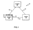
- an exemplary archival system 100 suitably includes an encoder 106, a playback unit 120 and a search engine 110.
- Encoder 106 suitably receives input content 108 from historical masters 208 (e.g. analog tape or film) or present time material 209 (i.e. live camera footage).
- Encoder 106 suitably converts the input material 108 to a digital format that can be recorded on a digital medium such as a DVD-ROM, DAT, laserdisk, digital memory, hard disk or the like.
- Digital content can be suitably produced in a variety of formats, and can be simultaneously provided to search engine 110 and to a digital archive.
- Search engine 110 facilitates convenient search and retrieval of digital content that can be retrieved from the archive and viewed on playback unit 120.
- the digital signals provided by encoder 106 suitably include timecodes associated with input data 108.
- encoder 106 may mark each input data frame (e.g. each video frame) with a digital code that identifies the location of the frame in the archive and allows for convenient retrieval of the frame.
- a time code scheme is described in Society of Motion Pictures and Television Engineers (SMPTE) Standard 12M dated 1986.
- SMPTE Society of Motion Pictures and Television Engineers
- Various timecode schemes include marking the frame with the actual time of day that the frame was recorded, the serialized frame number since the beginning of the tape, or a discontinuous timecode that facilitates accurate searching.
- each frame is suitably encoded with the time elapsed since the beginning of the input tape to create a unique identifier for each frame on the tape.
- encoder 106 may be configured to place the hours/minutes/seconds since the beginning of the tape into the digital output.
- a serialized number for frames elapsed during the last second of encoding or since some other point of reference may be placed on the digital output.
- the serialized portion of the timecode is replaced by or used in conjunction with a fractionalized time indicator (e.g. tenths or hundredths of a second).
- any of the various timecode formats may be suitably encoded in any portion of the standard MPEG header such as in the "user" or "timecode” fields.
- only a portion of the input video frames are encoded with time stamps, or various timecode methods are combined.
- the timecode is eliminated partially or entirely.
- shot sheet data 240 typically corresponds to hours/minutes/seconds/frames since the beginning of the analog tape, along with a written description of the tape content.
- One time code scheme suitable for use with the present invention involves converting the original analog timecode to a digital equivalent that is retained in the timecode field of output data streams 140 and 150. By placing a time code in the output digital stream that corresponds to the timecode on the original analog tape, the "shot sheet" data composed for the original analog tape may be used to quickly find indexed content on the archived medium, as described more fully below.
- Encoder 106 produces one or more streams of digital output data in any suitable format such as MPEG-1, MPEG-2, MPEG-4, H.261, H.263 or the like.
- MPEG-1 is a relatively low bit-rate, low-resolution image format that is fully described in ISO Standard 11172 dated 1993.
- MPEG-2 is a comparatively high-bit-rate, high-resolution video standard that is fully described in ISO Standard 13818 dated 1996.
- Various implementations and details of the MPEG standards are described in the book MPEG Video Compression Standard, Joan Mitchell et al., ISBN number 0-412-08771-5. In accordance with one aspect of the invention, basic standards are readily modified in various implementations.
- various bit rates and types of image compression can be selected based upon the needs of a particular implementation.
- various header fields described by the standards (such as the timecode fields) are frequently omitted or modified in various MPEG implementations, all of which are within the ambit of the present invention.
- optional recorder 104 receives the digitized signal from encoder 106 and stores the data on the selected medium or media.
- recorder 104 and encoder 106 are suitably combined into a single device.
- encoder 106 suitably produces multiple streams of digital data.
- encoder 106 may be implemented with multiple encoding devices.
- the Vibrint model 100 includes a chassis for accepting multiple encoder cards such that each encoder card supports a separate video stream on a separate output channel.
- multiple encoder units from various manufacturers can be combined to produce any desired combination of digital output channels.
- a working sub-master copy of the input data 108 is optionally produced.
- the working copy (not shown in Figure 1) is an interim copy of input date 108 that reduces the need for multiple reads of potentially sensitive input data 108, and may be erased after encoding is complete, if desired.
- the interim copy is preferably a high bit-rate, error-correcting component digital data format such as a Sony Digi-Beta or Panasonic D5, although any other digital or analog format such as DAT or analog tape could be used.
- Other embodiments simultaneously encode multiple streams of digital data by routing the input signal simultaneously to multiple encoder units, such as multiple encoding cards on a Vibrint Model 100.
- encoder 106 suitably produces a first video stream 150 at a high bit-rate (e.g. above about 4 mega bits per second, preferably about 10 mega bits per second), high-resolution format (such as MPEG-2) and a second video stream 140 in a relatively low bit-rate (e.g. below about 1,800 kilobits per second, preferably about 1,200 kilobits per second), low-resolution format (such as MPEG-1).
- a high bit-rate e.g. above about 4 mega bits per second, preferably about 10 mega bits per second
- high-resolution format such as MPEG-2
- second video stream 140 in a relatively low bit-rate (e.g. below about 1,800 kilobits per second, preferably about 1,200 kilobits per second), low-resolution format (such as MPEG-1).
- Each video stream is suitably produced by a separate encoding device (such as encoders 206 or 216 in Figure 2), or by a hybrid encoder capable of producing multiple output streams from a single input
- High-resolution output 150 is recorded on any suitable format for archival purposes, as discussed above.
- the media embodying high-resolution output 150 may be organized for storage in any desired fashion.
- output 150 may be stored on DAT tape and placed in one or more Sony Model DMS-8400 archive devices to form a library 220.
- library 220 may be stored on DVD-ROMs and warehoused or otherwise stored in any suitable form prior to retrieval. Because DVD-ROMs and other digital media are significantly smaller, lighter and more efficient than typical analog media, warehousing requirements are dramatically reduced. Moreover, digital media are much less susceptible to image degradation over time than analog forms of storage.
- Embodiments including low-resolution output 140 suitably provide a relatively low-resolution signal (such as an MPEG-1 stream) to a search engine 110 via a data link (e.g. fiber optic or other high-speed data connection, modem link, wireless link or the like) or via transferable media (e.g. DVD-ROM, CD-ROM, DAT, etc.).
- a data link e.g. fiber optic or other high-speed data connection, modem link, wireless link or the like
- transferable media e.g. DVD-ROM, CD-ROM, DAT, etc.
- Various embodiments include a computer server (such as a server based upon the Windows NT product available from the Microsoft Corp. of Redmond, Washington) that provides backup storage of encoded data 140.
- an alternate embodiment of encoding system 106 suitable for assembly into a vehicle that can be placed on location with a television station or other content source suitably includes digitizers, encoders, data connections and an optional server.
- digitizers, encoders, data connections and an optional server suitably includes digitizers, encoders, data connections and an optional server.
- Combining a number of encoders into units placed on a vehicle provides a number of advantages. First, the amount of time needed to create a large digital archive can be significantly reduced as many analog sources are simultaneously archived to digital format. Additionally, by placing the encoding equipment onto a vehicle that can be located at a source facility (e.g. a television station), the administration and risk of loss or damage associated with inventorying, packaging and shipping the potentially voluminous quantities of analog media are eliminated.
- a source facility e.g. a television station
- an analog media player 304 such as a tape machine suitably provides an analog video signal 306 and an analog audio signal 308 to encoders 206 and 216.
- Video and audio input signals 306 and 308 may also be provided to optional monitor devices 302A and 302B, respectively.
- a signal 310 corresponding to the timecode from the analog master is also suitably provided from the analog media player to encoders 206 and 216, which encode the timecode from the analog master into the digital output stream.
- An optional control signal 312 is also provided to encoder 216 and/or to encoder 206.
- Encoders 206 and 216 provide output as required, such as directly to a recording device or to a data network, as discussed below.
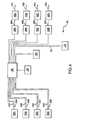
- a multiple-encoder unit 400 suitably includes multiple encoders 300A-D providing outputs 340A-D and 350A-D to a network such as an FDDI or ethernet hub 402.
- a network such as an FDDI or ethernet hub 402.
- FIG 4 Although only four encoders are shown in Figure 4, it will be appreciated that any number of encoders could be combined into a single mobile or fixed facility system. It is estimated that a unit with 32 encoders, for example, could archive approximately 5000 hours of content each month. Similarly, a 64-encoder unit could archive approximately 10,000 hours of programming each month.
- One or more data controllers 404A-D suitably receive digital data from network 402 and provide the data via data interfaces 408A-D to recording devices 406A-D, respectively.
- Interface 408A-D is any suitable form of data interface such as a SCSI, PCI or other data channel.
- controllers 404A-D may be omitted entirely such that recording devices 406A-D are coupled directly to network 402.
- the encoders 106 it will be appreciated that any number of recording devices could be used with the system, and the number of recording devices need not parallel the number of encoding devices.
- any form of recordable media could be used with the present invention, and therefore any suitable recording devices 406 such as DVD-ROM writers, CD-ROM writers, hard disk drives, floppy disk drives, DAT recorders or the like could be used.
- an optional CD-ROM writer 410 is included in tandem with other media writers to provide a convenient mode of storage for short video clips or other data
- network 402 suitably provides datastream 140 to search engine 110.
- Server 102 is communicably coupled with network 402 such that the server is capable of monitoring and controlling the archive process, as well as providing an optional backup function.
- network 402 such that the server is capable of monitoring and controlling the archive process, as well as providing an optional backup function.
- monitoring equipment such as video and audio monitors and digital computers (each having, for example, a display, a keyboard and a mouse) could be connected to 402 to assist a human operator in administering the archive system.
- monitoring and control of the system could be partially or entirely automated.
- content is selectively placed on digital media based upon human selections or automatic controls in order to, for example, eliminate commercials, reduce long pauses in speeches, debates or sporting events, or the like.
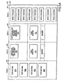
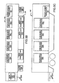
- Figures 5A, 5B and 5C provide more detailed schematics of an exemplary encoder system layout suitable for use in a semi-truck trailer.
- Figure 5A shows a workstation 500 that includes rack units 502, 504, 506 and 508 as well as one or more video monitors 510 and 512.
- the various components of encoding system 106 could of course be installed into rack units in any manner, the embodiment shown in Figure 5A includes four tape machines 304A-D installed in rack 502 and four sets of encoders 206A-D and 216A-D in rack 508.
- Racks 504 and 506 suitably include monitoring equipment such as timecode monitor 516 and control computer 514, which suitably includes a keyboard, mouse and monitor, as applicable.
- the various tape machines and encoders are suitably connected via a data network 402 (not shown in Figure 5A) or other suitable connection.
- Figures 5B and 5C show top and side views of an exemplary semi-trailer 540 that includes four four-source workstations 500A, 500B, 500C and 500D.
- a master logging workstation that suitably includes server 102 (not shown in Figure 5) or other hardware used to administer, monitor and control the archive system as appropriate is also provided.
- side 528 of trailer 540 may be configured to expand to provide extra space as necessary and to contract when trailer 540 is in transit.
- Access to trailer 540 is suitably provided by access ladders 524A and 524B, as well as by lift gate 526.
- one or more transfer carts 522 are provided such that the carts may be raised and lowered from the trailer via lift 526 to facilitate transfer of analog media into and out of trailer 540.
- a technician suitably loads analog media onto media cart 522 at a customer facility, for example, and transports the media to trailer 540 via the cart and gate 526 such that source material is readily available at each workstation 500. It will be appreciated that many different layouts for stationary or mobile encoding stations could be formulated, all within the ambit of the present invention.
- search engine 110 suitably includes a data repository 114 and a database management system (DBMS) 116.
- DBMS 116 suitably receives a digital data stream 140 from encoder 106 and stores the data in repository 114.
- DBMS 116 also maintains information (i.e. meta-data) about the encoded stream in a database 114.
- DBMS 116 is any database product such as SQL server from the Microsoft Corporation, Oracle8 software from the Oracle Corporation in Mountain View, California, DB2 database server from IBM, or the like running on a personal computer, UNIX workstation, minicomputer, or the like.
- database 110 may be configured to run on any personal computer or redundant arrays of inexpensive disks (RAID) system such as a model RAIDstack available from the AIWA corporation, preferably with a tape backup system that protects against the loss of video image data, running, for example, software available from the EXEBYTE corporation.
- RAID redundant arrays of inexpensive disks
- Meta-data stored in database 114 suitably includes date, tape number, and timecode data relating to information contained on data stream 140.
- various embodiments of the database include textual descriptions of the video indexed in the database according to timecodes.
- the textual descriptions may be input in any manner such as manual entry, scanning of written notes (such as "shot sheet” notes 240 made at the time the content was created), electronic conversion of audio content present in the datastream, or the like.
- an administrator may enter textual descriptions on the video content as the digital archive is created.
- the "shot sheet" notes or other written descriptions of the content may be scanned and converted into the proper database format (such as by any form of optical character recognition (OCR) software), or the written descriptions are entered into the database through any suitable technique.
- OCR optical character recognition
- the textual descriptions in database 110 suitably facilitate searching of the database to locate particular video segments desired.
- Users at workstations 202A-D interact with server 116 via network 210 to place various queries to database 114 and to view image clips from server 116. For example, users can query a particular episode of a favorite program, or an interview with a particular guest on a talk show, or a particular play in a sporting event.
- access to server 116 is provided via the Internet 205 through security firewall 204 (best seen in Figure 2).
- Firewall 204 suitably controls access to network 210 from network 205 though router access control lists, hardware or software controls, or the like.
- a search engine client program 602 running on workstations 202A-D suitably formats the users' query (for example, in SQL or any other database query language) and forwards the data request to server 116 for processing.
- the query is formed on database source display 610 based upon, for example, various search rules 612 that are related to the search software and the particular format of database used.
- the query is passed to DBMS 116 via database system interface 606 (which suitably converts the users query into SQL or another suitable format) and connection interface 604 (which suitably manages user accounts, security and permissions).
- DBMS 116 may be configured to receive user requests via network 210, searches data repository 114 and returns tape number and timecode information related to the query, along with any other information necessary to locate the desired clip on server 116.
- the database provides sufficient information (including tape number, timecode, etc. as necessary) to identify the particular video clip identified by the search.
- the server provides the requested image to the proper workstation 202.
- Client software 602 suitably receives the image data via connection interface 604 and database system interface 606, and displays the results to video display 608 via database display driver 610. The user can then review the clip, and forward the clip to an editing/production system 230 if desired. Alternatively, the user can save, email or print the results, as appropriate.
- An exemplary embodiment of a screen display from client software 602 is shown in Figure 6B.
- datastream 140 is suitably decoded by separating the digital stream into an audio component 702 and a video component 704, or though any other suitable method of decoding.
- the user can forward timecode and tape number information (or other information sufficient to locate the particular clip) to production workstation 230 ( Figure 2), which may then suitably retrieve the high-resolution clip from library 220.
- search engine 110 further include edit decision list (EDL) capability on server 116 or database 114.
- EDL edit decision list
- the EDL is a list of timecode locations on each tape that require scene changes or edits.
- playback unit 120 is any device capable of reading media embodying archive data stream 150.
- the type of playback device 120 required varies widely upon the particular implementation, and many devices for reading DVD, CD-ROM, DAT, laserdisk and other formats are commercially available.
- Playback unit 120 suitably includes input/output 830, a processor 806 and video processing system 820.
- Video processing system 820 suitably includes hardware circuitry and software that is formulated for reading data from a particular storage medium and for decoding the data itself.
- playback unit 120 is suitably fashioned to read DVD disks provided at DVD drive 802 Alternatively or in addition to DVD drive 802, unit 120 includes a hard drive 804 that preferably provides 2 gigabytes or more of data storage, although the particular amount of disk capacity will vary dramatically from about a gigabyte to a terabyte or more in various embodiments.
- unit 120 could be fashioned from conventional or non-conventional PC components.
- various units 120 including processing circuitry 806 having one or more microprocessors (such as those available from the Intel, Cyrix, AMD, Motorola, Texas Instruments, AT&T or other corporations) and supporting one or more bus architectures could be formulated, all within the ambit of the present invention.
- a personal computer motherboard such as a 400 MHz or faster motherboard including a PENTIUM microprocessor available from the Intel corporation of Menlo Park, California suitably integrates and controls the various playback components via a PCI bus architecture.
- Exemplary motherboards are available from the Intel corporation that also include SCSI interfaces to hard drives 804 and/or DVD drives 802.
- Decoding is suitably performed by any hardware or software decoder device 810 such as any of various MPEG decoders that are commercially available.
- An exemplary decoder device 810 is an MPEGLynx MPEG-2 decoder card (available from the Stradis corporation) that communicates with the motherboard 806 though a bus interface (such as a PCI slot) 812.
- decoding may be accomplished by software running in memory and communicating with processing circuitry 806.
- MPEG decoder system 820 suitably includes a reference decoder 818 that receives an external synchronization signal via, for example, a gen-lock input/output.
- the synchronization signal is suitably used to synchronize vertical, horizontal and color information during decoding.
- Decoder 810 suitably receives command information from the system bus via interface 812 and/or from an external remote control via an RS-422 interface 814 or other suitable external interface.
- Interface 814 also suitably decodes timecode information based upon commands received from processor 806 via the system bus. Decoded signals are suitably passed from decoder 810 to an external monitor via output driver 816.
- playback unit 120 is suitably controlled by user input from a touchscreen, from a remote control, or any other input device.
- Touchscreen (such as a Zworld model OP6500 ) may be connected to the processing circuitry 806 via a COM1 or COM2 port, for example.
- the COM port that is not connected to the touchscreen is connected via a conventional RS-232 to RS-422 adapter board 814 or other suitable interface to a remote control device.
- An exemplary adapter device is a model 1C470A from Black Box Corp. of Lawrence, PA, which can provide a SONY video tape recorder 9 pin input/output connected to an external connector panel (not shown).
- the connector panel also provides access to other inputs and outputs of the playback unit 120, such as electrical power input, a power switch, a gen-lock input, video and audio outputs, a network interface (such as an ethernet adapter), a female 9-pin 'D' connector (for remote control inputs via, for example, the SONY betacam or Odetics RS-422 interface protocol), and/or any other suitable inputs and outputs.
- other inputs and outputs of the playback unit 120 such as electrical power input, a power switch, a gen-lock input, video and audio outputs, a network interface (such as an ethernet adapter), a female 9-pin 'D' connector (for remote control inputs via, for example, the SONY betacam or Odetics RS-422 interface protocol), and/or any other suitable inputs and outputs.
- Playback unit 120 is suitably loaded via CD-ROM or DVD-ROM.
- playback unit 120 is designed to boot directly into an operating system such as Windows 98/NT/2000 that loads a server application without requiring keyboard, mouse or VGA monitor connections.
- the server application suitably provides a replacement for video tape player playback to access the archived material stored on DVD or on hard drive 804 or on another device.
- Users interact with the server application via the touchscreen, remote control, or another input device as appropriate.
- file names are displayed on the touchscreen and users are allowed to scroll through the various names to search for or select a desired video clip.
- An exemplary screen display is shown in Figure 9. As can be readily observed, the main screen provides a status display and motion control buttons as appropriate.
- the screen also suitably provides feedback on the particular video clip, such as the file name, file duration, etc. such that users select particular video clips to be viewed as desired.
- the users selects video clips by referencing a timecode on the video stream 150.
- Player 120 suitably locates the particular timecode and provides the relevant clip for viewing.
Landscapes
- Engineering & Computer Science (AREA)
- Multimedia (AREA)
- Signal Processing (AREA)
- Theoretical Computer Science (AREA)
- Databases & Information Systems (AREA)
- Human Computer Interaction (AREA)
- General Engineering & Computer Science (AREA)
- General Physics & Mathematics (AREA)
- Data Mining & Analysis (AREA)
- Library & Information Science (AREA)
- Physics & Mathematics (AREA)
- Management Or Editing Of Information On Record Carriers (AREA)
- Indexing, Searching, Synchronizing, And The Amount Of Synchronization Travel Of Record Carriers (AREA)
- Signal Processing For Digital Recording And Reproducing (AREA)
- Television Signal Processing For Recording (AREA)
- Two-Way Televisions, Distribution Of Moving Picture Or The Like (AREA)
- Circuits Of Receivers In General (AREA)
Abstract
Description
- The invention relates generally to methods and apparatus of archiving audio and video data. More particularly, the invention relates to systems for storing, viewing and searching audio and video data.
- Over the past several decades, television stations and other broadcast media have created millions of hours of film, videotape and the like capturing news, sports, entertainment and other information. Although much of the video content created and broadcast has been irretrievably lost, many hours of television and other video content remain archived on film, tape or other analog media. Existing video and film archives are disadvantageous in that they typically occupy large amounts of space. For example, a single hour of video imagery stored on 2" tape generally weighs in excess of twelve pounds and occupies more than 500 cubic inches of shelf space. Moreover, conventional analog media degrades quickly over time, thus causing the preserved image to degrade or disappear in a relatively short period of years.
- Further, presently available technologies are unable to conveniently index the archival footage so that a particular video clip can be sought out and readily retrieved. When video images are recorded, the cameraperson typically keeps a data log (such as a collection of individual pages called "shot sheets") that records the content of the video tape. Such logs are generally manually created, and are maintained in conjunction with the video tape. A typical "shot sheet" entry describes the recorded image along with an indication of the number of hours, minutes, seconds and frames that have elapsed since the beginning of the tape when the described image was shot. When the tape is reviewed at a later date, then, the relevant "shot sheet" can serve as an index to the tape's content.
- Examples of prior art technologies involving video management include U.S. Patent No. 5,852,435 to Vigneaux, et al., directed towards a newsroom production system, and U.S. Patent No. 5,488,433 to Washino, et al., directed towards a method for producing video programs.
- With the advent of digital video formats such as the MPEG standards created by the Motion Pictures Experts Group, digital storage techniques are now available that will degrade much slower than analog tape and permit storage in a variety of compact formats such as digital video disks (DVDs), optical analog laser disks, digital audio tapes (DATs) and CD-ROMs. Digital formats maintain high quality image data for long periods of time, and are generally capable of relatively quick retrieval. Several devices provide for mass storage of digital media. The Sony Model DMS-8400, for example, is an archival storage device that includes bins and robotic mechanisms for storing and retrieving multiple DATs containing MPEG or other digital data.
- Although such devices provide high capacity storage of digital data, a problem remains in efficiently converting archival analog footage to the new digital media. It is therefore desired to create a system for archiving information and images stored on videotape, film and other analog media into a convenient digital format. It is also desired to create a search and retrieval system that allows users to readily find and retrieve particular clips of archival footage.
- In accordance with one embodiment of the present invention, an analog to digital conversion system suitably includes an encoder producing one or more streams of digital data, each stream optionally including a digital timecode that corresponds to the timecode on the original analog tape. In accordance with one aspect of the invention, a high-resolution digital stream is maintained in a first digital medium for archival purposes. A second, low-resolution video stream is optionally provided to a search engine that includes a database of content information. The database is configured to allow users to search the low-resolution stream for a particular video segment and to view the segment from either the high or low-resolution video streams based upon their common, synchronized digital timecodes.
- The above and other features and advantages of the present invention are hereinafter described in the following detailed description of illustrative embodiments to be read in conjunction with the accompanying drawing figures, wherein like reference numerals are used to identify the same or similar parts in the similar views, and:
- FIGURE 1 is a block diagram of an exemplary archive creation system;
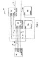
- FIGURE 2 is a block diagram of an exemplary archive creation system;
- FIGURE 3 is a block diagram of an exemplary embodiment of an encoder;
- FIGURE 4 is a schematic of an exemplary encoder system suitable for assembly in a vehicle;
- FIGURE 5A is a schematic of an exemplary rack system suitable for use in a vehicle or in a stationary encoding system;
- FIGURE 5B is a top view of an exemplary semi-trailer housing an exemplary encoding system;
- FIGURE 5C is a side view of an exemplary semi-trailer housing an exemplary encoding system;
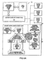
- FIGURE 6A is a block diagram of an exemplary search engine;
- FIGURE 6B is an exemplary screen display from an exemplary search engine;
- FIGURE 7 is a block diagram of an exemplary playback/decoder system;
- FIGURE 8 is a block diagram of an exemplary playback/decoder system; and
- FIGURE 9 is an exemplary screen display from an exemplary playback/decoder system.
-
- To simplify the description of the exemplary embodiments, the invention is frequently described as pertaining to video archiving systems, and broadcast television stations and networks in particular. It will be appreciated, however, that many applications of the present invention could be formulated. For example, the present invention could be used to archive motion picture film data, closed circuit video information, multimedia content, photographic, stereoscopic, holographic or any other form of moving video, still images, data or other information. Similarly, the present invention could be used to create archives of audio signals (for example in MP3 format), textual information, or any other form of data or information that may be represented in a digital format. With regard to video input, the present invention is suitable for use with NTSC video formats as well as high-definition digital television (HDTV) formats, internationally-used PAL formats, and the like.
- With momentary reference to Figures 1 and 2, an
exemplary archival system 100 suitably includes anencoder 106, aplayback unit 120 and asearch engine 110.Encoder 106 suitably receivesinput content 108 from historical masters 208 (e.g. analog tape or film) or present time material 209 (i.e. live camera footage).Encoder 106 suitably converts theinput material 108 to a digital format that can be recorded on a digital medium such as a DVD-ROM, DAT, laserdisk, digital memory, hard disk or the like. Digital content can be suitably produced in a variety of formats, and can be simultaneously provided tosearch engine 110 and to a digital archive.Search engine 110 facilitates convenient search and retrieval of digital content that can be retrieved from the archive and viewed onplayback unit 120. - In accordance with the present invention, the digital signals provided by
encoder 106 suitably include timecodes associated withinput data 108. For example,encoder 106 may mark each input data frame (e.g. each video frame) with a digital code that identifies the location of the frame in the archive and allows for convenient retrieval of the frame. One time code scheme is described in Society of Motion Pictures and Television Engineers (SMPTE) Standard 12M dated 1986. Various timecode schemes include marking the frame with the actual time of day that the frame was recorded, the serialized frame number since the beginning of the tape, or a discontinuous timecode that facilitates accurate searching. In the latter case, each frame is suitably encoded with the time elapsed since the beginning of the input tape to create a unique identifier for each frame on the tape. For example,encoder 106 may be configured to place the hours/minutes/seconds since the beginning of the tape into the digital output. In addition, a serialized number for frames elapsed during the last second of encoding or since some other point of reference (e.g. the start of the DVD or other recording media, the start of the source tape, or some other point of reference) may be placed on the digital output. Alternatively, the serialized portion of the timecode is replaced by or used in conjunction with a fractionalized time indicator (e.g. tenths or hundredths of a second). Any of the various timecode formats may be suitably encoded in any portion of the standard MPEG header such as in the "user" or "timecode" fields. In some embodiments of the present invention, only a portion of the input video frames are encoded with time stamps, or various timecode methods are combined. In still other embodiments (particularly those embodiments that eliminate the search engine 110), the timecode is eliminated partially or entirely. - As noted above, "shot sheet"
data 240 typically corresponds to hours/minutes/seconds/frames since the beginning of the analog tape, along with a written description of the tape content. One time code scheme suitable for use with the present invention involves converting the original analog timecode to a digital equivalent that is retained in the timecode field ofoutput data streams -
Encoder 106 produces one or more streams of digital output data in any suitable format such as MPEG-1, MPEG-2, MPEG-4, H.261, H.263 or the like. MPEG-1 is a relatively low bit-rate, low-resolution image format that is fully described inISO Standard 11172 dated 1993. MPEG-2 is a comparatively high-bit-rate, high-resolution video standard that is fully described in ISO Standard 13818 dated 1996. Various implementations and details of the MPEG standards are described in the book MPEG Video Compression Standard, Joan Mitchell et al., ISBN number 0-412-08771-5. In accordance with one aspect of the invention, basic standards are readily modified in various implementations. For example, various bit rates and types of image compression can be selected based upon the needs of a particular implementation. Moreover, the various header fields described by the standards (such as the timecode fields) are frequently omitted or modified in various MPEG implementations, all of which are within the ambit of the present invention. - Various suitable encoding devices are available including, for example, the Vibrint model MPression encoder and the Minerva Compressionist encoder. In various embodiments of the invention,
optional recorder 104 receives the digitized signal fromencoder 106 and stores the data on the selected medium or media. Alternatively,recorder 104 andencoder 106 are suitably combined into a single device. - In various embodiments of the invention (and as described more fully below),
encoder 106 suitably produces multiple streams of digital data. In such embodiments,encoder 106 may be implemented with multiple encoding devices. For example, theVibrint model 100 includes a chassis for accepting multiple encoder cards such that each encoder card supports a separate video stream on a separate output channel. Alternatively, multiple encoder units from various manufacturers can be combined to produce any desired combination of digital output channels. In some embodiments (particularly those requiring multiple output video streams from encoder 106), a working sub-master copy of theinput data 108 is optionally produced. The working copy (not shown in Figure 1) is an interim copy ofinput date 108 that reduces the need for multiple reads of potentiallysensitive input data 108, and may be erased after encoding is complete, if desired. The interim copy is preferably a high bit-rate, error-correcting component digital data format such as a Sony Digi-Beta or Panasonic D5, although any other digital or analog format such as DAT or analog tape could be used. Other embodiments simultaneously encode multiple streams of digital data by routing the input signal simultaneously to multiple encoder units, such as multiple encoding cards on aVibrint Model 100. - In embodiments such as those shown in Figures 1 and 2,
encoder 106 suitably produces afirst video stream 150 at a high bit-rate (e.g. above about 4 mega bits per second, preferably about 10 mega bits per second), high-resolution format (such as MPEG-2) and asecond video stream 140 in a relatively low bit-rate (e.g. below about 1,800 kilobits per second, preferably about 1,200 kilobits per second), low-resolution format (such as MPEG-1). Each video stream is suitably produced by a separate encoding device (such asencoders resolution output 150 is recorded on any suitable format for archival purposes, as discussed above. The media embodying high-resolution output 150 may be organized for storage in any desired fashion. For example,output 150 may be stored on DAT tape and placed in one or more Sony Model DMS-8400 archive devices to form alibrary 220. Alternatively,library 220 may be stored on DVD-ROMs and warehoused or otherwise stored in any suitable form prior to retrieval. Because DVD-ROMs and other digital media are significantly smaller, lighter and more efficient than typical analog media, warehousing requirements are dramatically reduced. Moreover, digital media are much less susceptible to image degradation over time than analog forms of storage. - Embodiments including low-
resolution output 140 suitably provide a relatively low-resolution signal (such as an MPEG-1 stream) to asearch engine 110 via a data link (e.g. fiber optic or other high-speed data connection, modem link, wireless link or the like) or via transferable media (e.g. DVD-ROM, CD-ROM, DAT, etc.). Various embodiments include a computer server (such as a server based upon the Windows NT product available from the Microsoft Corp. of Redmond, Washington) that provides backup storage of encodeddata 140. - With reference to Figure 3, an alternate embodiment of
encoding system 106 suitable for assembly into a vehicle that can be placed on location with a television station or other content source suitably includes digitizers, encoders, data connections and an optional server. Combining a number of encoders into units placed on a vehicle provides a number of advantages. First, the amount of time needed to create a large digital archive can be significantly reduced as many analog sources are simultaneously archived to digital format. Additionally, by placing the encoding equipment onto a vehicle that can be located at a source facility (e.g. a television station), the administration and risk of loss or damage associated with inventorying, packaging and shipping the potentially voluminous quantities of analog media are eliminated. - As can be readily ascertained from Figure 3, an
analog media player 304 such as a tape machine suitably provides ananalog video signal 306 and ananalog audio signal 308 toencoders optional monitor devices signal 310 corresponding to the timecode from the analog master is also suitably provided from the analog media player to encoders 206 and 216, which encode the timecode from the analog master into the digital output stream. Anoptional control signal 312 is also provided toencoder 216 and/or to encoder 206.Encoders - Referring now to Figure 4, a multiple-
encoder unit 400 suitably includesmultiple encoders 300A-D providing outputs 340A-D and 350A-D to a network such as an FDDI orethernet hub 402. Although only four encoders are shown in Figure 4, it will be appreciated that any number of encoders could be combined into a single mobile or fixed facility system. It is estimated that a unit with 32 encoders, for example, could archive approximately 5000 hours of content each month. Similarly, a 64-encoder unit could archive approximately 10,000 hours of programming each month. - One or
more data controllers 404A-D suitably receive digital data fromnetwork 402 and provide the data via data interfaces 408A-D torecording devices 406A-D, respectively.Interface 408A-D is any suitable form of data interface such as a SCSI, PCI or other data channel. Alternatively,controllers 404A-D may be omitted entirely such thatrecording devices 406A-D are coupled directly tonetwork 402. As with theencoders 106, it will be appreciated that any number of recording devices could be used with the system, and the number of recording devices need not parallel the number of encoding devices. Similarly, any form of recordable media could be used with the present invention, and therefore any suitable recording devices 406 such as DVD-ROM writers, CD-ROM writers, hard disk drives, floppy disk drives, DAT recorders or the like could be used. In various embodiments, an optional CD-ROM writer 410 is included in tandem with other media writers to provide a convenient mode of storage for short video clips or other data Additionally, in various embodiments,network 402 suitably providesdatastream 140 tosearch engine 110. -
Server 102 is communicably coupled withnetwork 402 such that the server is capable of monitoring and controlling the archive process, as well as providing an optional backup function. Although not shown in Figure 4, it will be understood that various monitoring equipment such video and audio monitors and digital computers (each having, for example, a display, a keyboard and a mouse) could be connected to 402 to assist a human operator in administering the archive system. Alternatively, monitoring and control of the system could be partially or entirely automated. In various embodiments, content is selectively placed on digital media based upon human selections or automatic controls in order to, for example, eliminate commercials, reduce long pauses in speeches, debates or sporting events, or the like. - Figures 5A, 5B and 5C provide more detailed schematics of an exemplary encoder system layout suitable for use in a semi-truck trailer. Figure 5A, for example, shows a
workstation 500 that includesrack units encoding system 106 could of course be installed into rack units in any manner, the embodiment shown in Figure 5A includes fourtape machines 304A-D installed inrack 502 and four sets of encoders 206A-D and 216A-D inrack 508.Racks - Figures 5B and 5C show top and side views of an
exemplary semi-trailer 540 that includes four four-source workstations side 528 oftrailer 540 may be configured to expand to provide extra space as necessary and to contract whentrailer 540 is in transit. Access totrailer 540 is suitably provided byaccess ladders lift gate 526. In various embodiments, one or more transfer carts 522 are provided such that the carts may be raised and lowered from the trailer vialift 526 to facilitate transfer of analog media into and out oftrailer 540. A technician suitably loads analog media onto media cart 522 at a customer facility, for example, and transports the media totrailer 540 via the cart andgate 526 such that source material is readily available at eachworkstation 500. It will be appreciated that many different layouts for stationary or mobile encoding stations could be formulated, all within the ambit of the present invention. - Referring now to Figure 6A,
search engine 110 suitably includes adata repository 114 and a database management system (DBMS) 116.DBMS 116 suitably receives adigital data stream 140 fromencoder 106 and stores the data inrepository 114.DBMS 116 also maintains information (i.e. meta-data) about the encoded stream in adatabase 114.DBMS 116 is any database product such as SQL server from the Microsoft Corporation, Oracle8 software from the Oracle Corporation in Mountain View, California, DB2 database server from IBM, or the like running on a personal computer, UNIX workstation, minicomputer, or the like. Alternatively,database 110 may be configured to run on any personal computer or redundant arrays of inexpensive disks (RAID) system such as a model RAIDstack available from the AIWA corporation, preferably with a tape backup system that protects against the loss of video image data, running, for example, software available from the EXEBYTE corporation. - Meta-data stored in
database 114 suitably includes date, tape number, and timecode data relating to information contained ondata stream 140. Additionally, various embodiments of the database include textual descriptions of the video indexed in the database according to timecodes. The textual descriptions may be input in any manner such as manual entry, scanning of written notes (such as "shot sheet" notes 240 made at the time the content was created), electronic conversion of audio content present in the datastream, or the like. In some embodiments, an administrator may enter textual descriptions on the video content as the digital archive is created. Alternatively, the "shot sheet" notes or other written descriptions of the content may be scanned and converted into the proper database format (such as by any form of optical character recognition (OCR) software), or the written descriptions are entered into the database through any suitable technique. - The textual descriptions in
database 110 suitably facilitate searching of the database to locate particular video segments desired. Users atworkstations 202A-D interact withserver 116 vianetwork 210 to place various queries todatabase 114 and to view image clips fromserver 116. For example, users can query a particular episode of a favorite program, or an interview with a particular guest on a talk show, or a particular play in a sporting event. In various embodiments, access toserver 116 is provided via theInternet 205 through security firewall 204 (best seen in Figure 2).Firewall 204 suitably controls access tonetwork 210 fromnetwork 205 though router access control lists, hardware or software controls, or the like. - Referring again to Figure 6A, a search
engine client program 602 running onworkstations 202A-D suitably formats the users' query (for example, in SQL or any other database query language) and forwards the data request toserver 116 for processing. The query is formed ondatabase source display 610 based upon, for example,various search rules 612 that are related to the search software and the particular format of database used. The query is passed to DBMS 116 via database system interface 606 (which suitably converts the users query into SQL or another suitable format) and connection interface 604 (which suitably manages user accounts, security and permissions).DBMS 116 may be configured to receive user requests vianetwork 210, searchesdata repository 114 and returns tape number and timecode information related to the query, along with any other information necessary to locate the desired clip onserver 116. The database provides sufficient information (including tape number, timecode, etc. as necessary) to identify the particular video clip identified by the search. The server provides the requested image to theproper workstation 202. -
Client software 602 suitably receives the image data viaconnection interface 604 and database system interface 606, and displays the results tovideo display 608 viadatabase display driver 610. The user can then review the clip, and forward the clip to an editing/production system 230 if desired. Alternatively, the user can save, email or print the results, as appropriate. An exemplary embodiment of a screen display fromclient software 602 is shown in Figure 6B. - As shown in Figure 7,
datastream 140 is suitably decoded by separating the digital stream into anaudio component 702 and avideo component 704, or though any other suitable method of decoding. Alternatively, the user can forward timecode and tape number information (or other information sufficient to locate the particular clip) to production workstation 230 (Figure 2), which may then suitably retrieve the high-resolution clip fromlibrary 220. - Various embodiments of
search engine 110 further include edit decision list (EDL) capability onserver 116 ordatabase 114. The EDL is a list of timecode locations on each tape that require scene changes or edits. By maintaining edit requirement information in a database, search times associated with edits are significantly reduced. - With reference to Figure 8,
playback unit 120 is any device capable of reading media embodyingarchive data stream 150. The type ofplayback device 120 required varies widely upon the particular implementation, and many devices for reading DVD, CD-ROM, DAT, laserdisk and other formats are commercially available. For example, a digital DVD player could be used to read MPEG2 data recorded on a recordable DVDs.Playback unit 120 suitably includes input/output 830, a processor 806 andvideo processing system 820.Video processing system 820 suitably includes hardware circuitry and software that is formulated for reading data from a particular storage medium and for decoding the data itself. - In exemplary embodiments using MPEG-2 data recorded on DVD-ROM disks,
playback unit 120 is suitably fashioned to read DVD disks provided atDVD drive 802 Alternatively or in addition toDVD drive 802,unit 120 includes ahard drive 804 that preferably provides 2 gigabytes or more of data storage, although the particular amount of disk capacity will vary dramatically from about a gigabyte to a terabyte or more in various embodiments. Of course many variations ofplayback unit 120 could be fashioned from conventional or non-conventional PC components. For example,various units 120 including processing circuitry 806 having one or more microprocessors (such as those available from the Intel, Cyrix, AMD, Motorola, Texas Instruments, AT&T or other corporations) and supporting one or more bus architectures could be formulated, all within the ambit of the present invention. In one embodiment, a personal computer motherboard such as a 400 MHz or faster motherboard including a PENTIUM microprocessor available from the Intel corporation of Menlo Park, California suitably integrates and controls the various playback components via a PCI bus architecture. Exemplary motherboards are available from the Intel corporation that also include SCSI interfaces tohard drives 804 and/or DVD drives 802. - Decoding is suitably performed by any hardware or
software decoder device 810 such as any of various MPEG decoders that are commercially available. Anexemplary decoder device 810 is an MPEGLynx MPEG-2 decoder card (available from the Stradis corporation) that communicates with the motherboard 806 though a bus interface (such as a PCI slot) 812. Alternatively, decoding may be accomplished by software running in memory and communicating with processing circuitry 806. -
MPEG decoder system 820 suitably includes areference decoder 818 that receives an external synchronization signal via, for example, a gen-lock input/output. The synchronization signal is suitably used to synchronize vertical, horizontal and color information during decoding.Decoder 810 suitably receives command information from the system bus via interface 812 and/or from an external remote control via an RS-422interface 814 or other suitable external interface.Interface 814 also suitably decodes timecode information based upon commands received from processor 806 via the system bus. Decoded signals are suitably passed fromdecoder 810 to an external monitor viaoutput driver 816. - In the illustrated embodiment,
playback unit 120 is suitably controlled by user input from a touchscreen, from a remote control, or any other input device. Touchscreen (such as a Zworld model OP6500 ) may be connected to the processing circuitry 806 via a COM1 or COM2 port, for example. In various embodiments, the COM port that is not connected to the touchscreen is connected via a conventional RS-232 to RS-422 adapter board 814 or other suitable interface to a remote control device. An exemplary adapter device is a model 1C470A from Black Box Corp. of Lawrence, PA, which can provide a SONY video tape recorder 9 pin input/output connected to an external connector panel (not shown). The connector panel also provides access to other inputs and outputs of theplayback unit 120, such as electrical power input, a power switch, a gen-lock input, video and audio outputs, a network interface (such as an ethernet adapter), a female 9-pin 'D' connector (for remote control inputs via, for example, the SONY betacam or Odetics RS-422 interface protocol), and/or any other suitable inputs and outputs. - Software for
playback unit 120 is suitably loaded via CD-ROM or DVD-ROM. In various embodiments,playback unit 120 is designed to boot directly into an operating system such as Windows 98/NT/2000 that loads a server application without requiring keyboard, mouse or VGA monitor connections. The server application suitably provides a replacement for video tape player playback to access the archived material stored on DVD or onhard drive 804 or on another device. Users interact with the server application via the touchscreen, remote control, or another input device as appropriate. Typically, file names are displayed on the touchscreen and users are allowed to scroll through the various names to search for or select a desired video clip. An exemplary screen display is shown in Figure 9. As can be readily observed, the main screen provides a status display and motion control buttons as appropriate. The screen also suitably provides feedback on the particular video clip, such as the file name, file duration, etc. such that users select particular video clips to be viewed as desired. In various embodiments, the users selects video clips by referencing a timecode on thevideo stream 150.Player 120 suitably locates the particular timecode and provides the relevant clip for viewing. - The corresponding structures, materials, acts and equivalents of all elements in the claims below are intended to include any structure, material or acts for performing the functions in combination with other claimed elements as specifically claimed. The scope of the invention should be determined by the appended claims and their legal equivalents, rather than by the examples given above.
Claims (20)
- A method of creating an archive, the method characterized by the steps ofallowing at least one digital encoder (e.g.., 106) to receive an input signal (e.g.., 108), the input further including a timecode and a content;digitizing, by the encoder (e.g.., 106), each input signal and generating at least a first digital output signal and a second digital output signal, the first output signal corresponding to timecode reference information, the second output signal corresponding to the content (e.g.., 108); andstoring the first digital output signal and the second digital output signal on a storage media (e.g., 114).
- The method of claim 1 further characterized by the step of introducing a computer system (e.g., 110) in communication with the encoder (e.g.., 106) and the media storage, the computer system (e.g., 110) being configured to locate the second digital output signal on the storage media (e.g., 114) based on the first digital output signal.
- The method of claim 2 further characterized by the step of introducing a playback device (e.g., 120), the playback device (e.g., 120) in communication with the computer system (e.g., 110) and being configured to display the at least second digital output signal from the storage media (e.g., 114).
- The method of claim 3 further characterized by the step of allowing the playback device (e.g., 120) to display the at least first digital output signal from the storage media (e.g., 114).
- The method of claim 2 further characterized by the step of allowing the playback device (e.g., 120) to display the at least first digital output signal from the storage media (e.g., 114) simultaneously with the at least second digital output signal.
- The method of claim 5 further characterized by the steps of allowing the encoder (e.g.., 105) to generate at least a third digital output signal and allowing the computer system (e.g., 110) to store the at least third digital output signal on the storage media (e.g., 114).
- The method of claim 6 further characterized by the step of allowing the playback device (e.g., 120) to display the at least third digital output signal from the storage media (e.g., 114).
- The method of claim 7, the third digital output signal being selected from the group consisting of an audio signal (e.g., 308), a video signal (e.g., 306), a text-based signal (e.g., 240) and an optical character recognition signal.
- The method of claim 4, the encoder (e.g.., 106), computer system (e.g., 110), storage media (e.g., 114) and playback device (e.g., 120) being installed in a vehicle (e.g., 540).
- The method of claim 4, the timecode being continuous.
- The method of claim 4, the timecode being discontinuous.
- A system for archiving a signal, the signal including timecode information, the system characterized by:at least one digital encoder (e.g.,, 106) configured to receive at least one input signal (e.g., 108), the input signal (e.g., 108) further including content, the encoder (e.g.., 106) digitizing each input signal (e.g., 108) and generating at least a first digital output signal and a second digital output signal, the first output signal corresponding to timecode reference information, the second output signal corresponding to the content, the first output signal having an archival relationship with the second output signal;at least one storage media (e.g., 114) in communication with each digital encoder (e.g.., 106), each storage media (e.g., 114) configured to store the first digital output signal relative to the second digital output signal.
- The system of claim 12 further characterized by at least one search engine (e.g., 110) in communication with the encoder (e.g.., 106) and the media storage, each search engine (e.g., 110) being configured to facilitate locating the first digital output signal.
- The system of claim 13 further characterized by at least one playback device (e.g., 120) in communication with at least one search engine (e.g., 110), each playback device (e.g., 120) being configured to display the first digital output signal and the second output signal.
- The system of claim 14, the search engine (e.g., 110) further characterized by a database (e.g., 114) storing the first digital output signal and the second output signal, and a search engine (e.g., 110) client configured to retrieve data from the database (e.g., 114) in response to instructions from a user.
- The system of claim 15, each search engine (e.g., 110) further characterized as a server (e.g., 116), each server (e.g., 116) being configured to receive descriptive information from the user and store the descriptive information.
- The system of claim 14, the descriptive information depicting the second digital output signal.
- The system of claim 14, the playback device (e.g., 120) further configured to transmit a playback signal to a broadcast system.
- The system of claim 18 the encoder (e.g.., 106), computer system (e.g., 110), search engine (e.g., 110), storage media (e.g., 114) and playback device (e.g., 120) being installed in a vehicle.
- The system of claim 19, the encoder (eg., 106), computer system (e.g., 110), search engine (e.g., 110), storage media (e.g., 114) and playback device (e.g., 120) being installed in a vehicle.
Applications Claiming Priority (5)
| Application Number | Priority Date | Filing Date | Title |
|---|---|---|---|
| US537073 | 1983-09-29 | ||
| US13586799P | 1999-05-25 | 1999-05-25 | |
| US135867P | 1999-05-25 | ||
| US53707300A | 2000-03-28 | 2000-03-28 | |
| PCT/US2000/008487 WO2000072186A2 (en) | 1999-05-25 | 2000-03-29 | Method and apparatus for creating digital archives |
Publications (2)
| Publication Number | Publication Date |
|---|---|
| EP1181649A1 EP1181649A1 (en) | 2002-02-27 |
| EP1181649B1 true EP1181649B1 (en) | 2003-03-05 |
Family
ID=26833762
Family Applications (1)
| Application Number | Title | Priority Date | Filing Date |
|---|---|---|---|
| EP00919902A Expired - Lifetime EP1181649B1 (en) | 1999-05-25 | 2000-03-29 | Method and apparatus for creating digital archives |
Country Status (6)
| Country | Link |
|---|---|
| EP (1) | EP1181649B1 (en) |
| AT (1) | ATE233922T1 (en) |
| AU (1) | AU4051900A (en) |
| CA (1) | CA2371623A1 (en) |
| DE (1) | DE60001562D1 (en) |
| WO (1) | WO2000072186A2 (en) |
Families Citing this family (10)
| Publication number | Priority date | Publication date | Assignee | Title |
|---|---|---|---|---|
| CN101208633B (en) | 2005-06-27 | 2011-12-07 | 汤姆森许可贸易公司 | Organization of archival elements for analog/digital hybrid data on film |
| US20070217761A1 (en) | 2006-03-07 | 2007-09-20 | Coban Research And Technologies, Inc. | Method for video/audio recording using unrestricted pre-event/post-event buffering with multiple bit and frame rates buffer files |
| US8941735B2 (en) | 2008-07-25 | 2015-01-27 | International Business Machines Corporation | Network based real-time analytics of raw video streams |
| US8325228B2 (en) | 2008-07-25 | 2012-12-04 | International Business Machines Corporation | Performing real-time analytics using a network processing solution able to directly ingest IP camera video streams |
| US9225527B1 (en) | 2014-08-29 | 2015-12-29 | Coban Technologies, Inc. | Hidden plug-in storage drive for data integrity |
| US9307317B2 (en) | 2014-08-29 | 2016-04-05 | Coban Technologies, Inc. | Wireless programmable microphone apparatus and system for integrated surveillance system devices |
| US10165171B2 (en) | 2016-01-22 | 2018-12-25 | Coban Technologies, Inc. | Systems, apparatuses, and methods for controlling audiovisual apparatuses |
| US10152858B2 (en) | 2016-05-09 | 2018-12-11 | Coban Technologies, Inc. | Systems, apparatuses and methods for triggering actions based on data capture and characterization |
| US10789840B2 (en) | 2016-05-09 | 2020-09-29 | Coban Technologies, Inc. | Systems, apparatuses and methods for detecting driving behavior and triggering actions based on detected driving behavior |
| US10370102B2 (en) | 2016-05-09 | 2019-08-06 | Coban Technologies, Inc. | Systems, apparatuses and methods for unmanned aerial vehicle |
Family Cites Families (4)
| Publication number | Priority date | Publication date | Assignee | Title |
|---|---|---|---|---|
| US5488433A (en) * | 1993-04-21 | 1996-01-30 | Kinya Washino | Dual compression format digital video production system |
| US5835667A (en) * | 1994-10-14 | 1998-11-10 | Carnegie Mellon University | Method and apparatus for creating a searchable digital video library and a system and method of using such a library |
| US5485611A (en) * | 1994-12-30 | 1996-01-16 | Intel Corporation | Video database indexing and method of presenting video database index to a user |
| US5852435A (en) * | 1996-04-12 | 1998-12-22 | Avid Technology, Inc. | Digital multimedia editing and data management system |
-
2000
- 2000-03-29 WO PCT/US2000/008487 patent/WO2000072186A2/en not_active Ceased
- 2000-03-29 AT AT00919902T patent/ATE233922T1/en not_active IP Right Cessation
- 2000-03-29 DE DE60001562T patent/DE60001562D1/en not_active Expired - Lifetime
- 2000-03-29 AU AU40519/00A patent/AU4051900A/en not_active Abandoned
- 2000-03-29 EP EP00919902A patent/EP1181649B1/en not_active Expired - Lifetime
- 2000-03-29 CA CA002371623A patent/CA2371623A1/en not_active Abandoned
Also Published As
| Publication number | Publication date |
|---|---|
| ATE233922T1 (en) | 2003-03-15 |
| WO2000072186A3 (en) | 2001-07-26 |
| EP1181649A1 (en) | 2002-02-27 |
| DE60001562D1 (en) | 2003-04-10 |
| CA2371623A1 (en) | 2000-11-30 |
| AU4051900A (en) | 2000-12-12 |
| WO2000072186A2 (en) | 2000-11-30 |
Similar Documents
| Publication | Publication Date | Title |
|---|---|---|
| US7280738B2 (en) | Method and system for specifying a selection of content segments stored in different formats | |
| Mauthe et al. | Professional content management systems: handling digital media assets | |
| JP4267244B2 (en) | Content generation and editing system, content generation and editing method, and computer program for executing the method | |
| US6870887B2 (en) | Method and system for synchronization between different content encoding formats | |
| US6947598B2 (en) | Methods and apparatus for generating, including and using information relating to archived audio/video data | |
| US7035468B2 (en) | Methods and apparatus for archiving, indexing and accessing audio and video data | |
| DE69900204T2 (en) | Information recording medium, device and method for data recording or reproduction | |
| US8634705B2 (en) | Methods and apparatus for indexing and archiving encoded audio/video data | |
| US5832171A (en) | System for creating video of an event with a synchronized transcript | |
| JP3883579B2 (en) | Multimedia system with improved data management mechanism | |
| DE69914111T2 (en) | An information recording medium, apparatus and method for reproducing data therefrom | |
| US5852435A (en) | Digital multimedia editing and data management system | |
| US20030031461A1 (en) | Video signal processing device and method | |
| CA2371623A1 (en) | Method and apparatus for creating digital archives | |
| JP2002281433A (en) | Moving image search / browsing / editing apparatus and recording medium | |
| US6771878B1 (en) | System for storing, restoring and distributing video-films from optical disks | |
| US20050232610A1 (en) | User automated content deletion | |
| KR100967972B1 (en) | Recording method | |
| US6347180B1 (en) | Signal processor | |
| US6374038B2 (en) | Tape recording of video signals | |
| KR102422450B1 (en) | Method for managing media data and sensing data | |
| JP3104854B2 (en) | Data supply system | |
| Heitmann | User Requirements and Technologies for Automated Storage and Retrieval: Interim Report of the SMPTE Study Group on User Requirements for Future Automated Storage and Retrieval Systems (V16. 09) | |
| Tanno et al. | Petabyte‐class video archive system with large‐scale automatic tape feed robot | |
| JP2952908B2 (en) | Library search device for video storage media for storage |
Legal Events
| Date | Code | Title | Description |
|---|---|---|---|
| PUAI | Public reference made under article 153(3) epc to a published international application that has entered the european phase |
Free format text: ORIGINAL CODE: 0009012 |
|
| 17P | Request for examination filed |
Effective date: 20011129 |
|
| AK | Designated contracting states |
Kind code of ref document: A1 Designated state(s): AT BE CH CY DE DK ES FI FR GB GR IE IT LI LU MC NL PT SE |
|
| AX | Request for extension of the european patent |
Free format text: AL;LT;LV;MK;RO;SI |
|
| GRAG | Despatch of communication of intention to grant |
Free format text: ORIGINAL CODE: EPIDOS AGRA |
|
| 17Q | First examination report despatched |
Effective date: 20020515 |
|
| GRAG | Despatch of communication of intention to grant |
Free format text: ORIGINAL CODE: EPIDOS AGRA |
|
| GRAH | Despatch of communication of intention to grant a patent |
Free format text: ORIGINAL CODE: EPIDOS IGRA |
|
| GRAH | Despatch of communication of intention to grant a patent |
Free format text: ORIGINAL CODE: EPIDOS IGRA |
|
| GRAA | (expected) grant |
Free format text: ORIGINAL CODE: 0009210 |
|
| AK | Designated contracting states |
Designated state(s): AT BE CH CY DE DK ES FI FR GB GR IE IT LI LU MC NL PT SE |
|
| PG25 | Lapsed in a contracting state [announced via postgrant information from national office to epo] |
Ref country code: IT Free format text: LAPSE BECAUSE OF FAILURE TO SUBMIT A TRANSLATION OF THE DESCRIPTION OR TO PAY THE FEE WITHIN THE PRESCRIBED TIME-LIMIT;WARNING: LAPSES OF ITALIAN PATENTS WITH EFFECTIVE DATE BEFORE 2007 MAY HAVE OCCURRED AT ANY TIME BEFORE 2007. THE CORRECT EFFECTIVE DATE MAY BE DIFFERENT FROM THE ONE RECORDED. Effective date: 20030305 Ref country code: NL Free format text: LAPSE BECAUSE OF FAILURE TO SUBMIT A TRANSLATION OF THE DESCRIPTION OR TO PAY THE FEE WITHIN THE PRESCRIBED TIME-LIMIT Effective date: 20030305 Ref country code: GR Free format text: LAPSE BECAUSE OF FAILURE TO SUBMIT A TRANSLATION OF THE DESCRIPTION OR TO PAY THE FEE WITHIN THE PRESCRIBED TIME-LIMIT Effective date: 20030305 Ref country code: FI Free format text: LAPSE BECAUSE OF FAILURE TO SUBMIT A TRANSLATION OF THE DESCRIPTION OR TO PAY THE FEE WITHIN THE PRESCRIBED TIME-LIMIT Effective date: 20030305 Ref country code: BE Free format text: LAPSE BECAUSE OF FAILURE TO SUBMIT A TRANSLATION OF THE DESCRIPTION OR TO PAY THE FEE WITHIN THE PRESCRIBED TIME-LIMIT Effective date: 20030305 Ref country code: AT Free format text: LAPSE BECAUSE OF FAILURE TO SUBMIT A TRANSLATION OF THE DESCRIPTION OR TO PAY THE FEE WITHIN THE PRESCRIBED TIME-LIMIT Effective date: 20030305 Ref country code: FR Free format text: LAPSE BECAUSE OF FAILURE TO SUBMIT A TRANSLATION OF THE DESCRIPTION OR TO PAY THE FEE WITHIN THE PRESCRIBED TIME-LIMIT Effective date: 20030305 Ref country code: CH Free format text: LAPSE BECAUSE OF FAILURE TO SUBMIT A TRANSLATION OF THE DESCRIPTION OR TO PAY THE FEE WITHIN THE PRESCRIBED TIME-LIMIT Effective date: 20030305 Ref country code: LI Free format text: LAPSE BECAUSE OF FAILURE TO SUBMIT A TRANSLATION OF THE DESCRIPTION OR TO PAY THE FEE WITHIN THE PRESCRIBED TIME-LIMIT Effective date: 20030305 |
|
| REG | Reference to a national code |
Ref country code: GB Ref legal event code: FG4D |
|
| REG | Reference to a national code |
Ref country code: CH Ref legal event code: EP |
|
| PG25 | Lapsed in a contracting state [announced via postgrant information from national office to epo] |
Ref country code: LU Free format text: LAPSE BECAUSE OF NON-PAYMENT OF DUE FEES Effective date: 20030329 Ref country code: CY Free format text: LAPSE BECAUSE OF FAILURE TO SUBMIT A TRANSLATION OF THE DESCRIPTION OR TO PAY THE FEE WITHIN THE PRESCRIBED TIME-LIMIT Effective date: 20030329 |
|
| PG25 | Lapsed in a contracting state [announced via postgrant information from national office to epo] |
Ref country code: MC Free format text: LAPSE BECAUSE OF NON-PAYMENT OF DUE FEES Effective date: 20030331 Ref country code: IE Free format text: LAPSE BECAUSE OF NON-PAYMENT OF DUE FEES Effective date: 20030331 |
|
| REG | Reference to a national code |
Ref country code: IE Ref legal event code: FG4D |
|
| REF | Corresponds to: |
Ref document number: 60001562 Country of ref document: DE Date of ref document: 20030410 Kind code of ref document: P |
|
| PG25 | Lapsed in a contracting state [announced via postgrant information from national office to epo] |
Ref country code: DK Free format text: LAPSE BECAUSE OF FAILURE TO SUBMIT A TRANSLATION OF THE DESCRIPTION OR TO PAY THE FEE WITHIN THE PRESCRIBED TIME-LIMIT Effective date: 20030605 Ref country code: SE Free format text: LAPSE BECAUSE OF FAILURE TO SUBMIT A TRANSLATION OF THE DESCRIPTION OR TO PAY THE FEE WITHIN THE PRESCRIBED TIME-LIMIT Effective date: 20030605 |
|
| PG25 | Lapsed in a contracting state [announced via postgrant information from national office to epo] |
Ref country code: DE Free format text: LAPSE BECAUSE OF FAILURE TO SUBMIT A TRANSLATION OF THE DESCRIPTION OR TO PAY THE FEE WITHIN THE PRESCRIBED TIME-LIMIT Effective date: 20030606 Ref country code: PT Free format text: LAPSE BECAUSE OF FAILURE TO SUBMIT A TRANSLATION OF THE DESCRIPTION OR TO PAY THE FEE WITHIN THE PRESCRIBED TIME-LIMIT Effective date: 20030606 |
|
| NLV1 | Nl: lapsed or annulled due to failure to fulfill the requirements of art. 29p and 29m of the patents act | ||
| LTIE | Lt: invalidation of european patent or patent extension |
Effective date: 20030305 |
|
| REG | Reference to a national code |
Ref country code: CH Ref legal event code: PL |
|
| PG25 | Lapsed in a contracting state [announced via postgrant information from national office to epo] |
Ref country code: ES Free format text: LAPSE BECAUSE OF FAILURE TO SUBMIT A TRANSLATION OF THE DESCRIPTION OR TO PAY THE FEE WITHIN THE PRESCRIBED TIME-LIMIT Effective date: 20030930 |
|
| PLBE | No opposition filed within time limit |
Free format text: ORIGINAL CODE: 0009261 |
|
| STAA | Information on the status of an ep patent application or granted ep patent |
Free format text: STATUS: NO OPPOSITION FILED WITHIN TIME LIMIT |
|
| REG | Reference to a national code |
Ref country code: IE Ref legal event code: MM4A |
|
| EN | Fr: translation not filed | ||
| 26N | No opposition filed |
Effective date: 20031208 |
|
| PG25 | Lapsed in a contracting state [announced via postgrant information from national office to epo] |
Ref country code: GB Free format text: LAPSE BECAUSE OF NON-PAYMENT OF DUE FEES Effective date: 20040329 |
|
| GBPC | Gb: european patent ceased through non-payment of renewal fee |
Effective date: 20040329 |