EP1181071B1 - Manifold and regulator apparatus - Google Patents
Manifold and regulator apparatus Download PDFInfo
- Publication number
- EP1181071B1 EP1181071B1 EP00937825A EP00937825A EP1181071B1 EP 1181071 B1 EP1181071 B1 EP 1181071B1 EP 00937825 A EP00937825 A EP 00937825A EP 00937825 A EP00937825 A EP 00937825A EP 1181071 B1 EP1181071 B1 EP 1181071B1
- Authority
- EP
- European Patent Office
- Prior art keywords
- outlet
- inlet
- manifold
- regulator
- manifold assembly
- Prior art date
- Legal status (The legal status is an assumption and is not a legal conclusion. Google has not performed a legal analysis and makes no representation as to the accuracy of the status listed.)
- Expired - Lifetime
Links
Images




Classifications
-
- A—HUMAN NECESSITIES
- A61—MEDICAL OR VETERINARY SCIENCE; HYGIENE
- A61G—TRANSPORT, PERSONAL CONVEYANCES OR ACCOMMODATION SPECIALLY ADAPTED FOR PATIENTS OR DISABLED PERSONS; OPERATING TABLES OR CHAIRS; CHAIRS FOR DENTISTRY; FUNERAL DEVICES
- A61G12/00—Accommodation for nursing, e.g. in hospitals, not covered by groups A61G1/00 - A61G11/00, e.g. trolleys for transport of medicaments or food; Prescription lists
- A61G12/001—Trolleys for transport of medicaments, food, linen, nursing supplies
-
- A—HUMAN NECESSITIES
- A61—MEDICAL OR VETERINARY SCIENCE; HYGIENE
- A61G—TRANSPORT, PERSONAL CONVEYANCES OR ACCOMMODATION SPECIALLY ADAPTED FOR PATIENTS OR DISABLED PERSONS; OPERATING TABLES OR CHAIRS; CHAIRS FOR DENTISTRY; FUNERAL DEVICES
- A61G12/00—Accommodation for nursing, e.g. in hospitals, not covered by groups A61G1/00 - A61G11/00, e.g. trolleys for transport of medicaments or food; Prescription lists
- A61G12/002—Supply appliances, e.g. columns for gas, fluid, electricity supply
- A61G12/005—Supply appliances, e.g. columns for gas, fluid, electricity supply mounted on the wall
-
- A—HUMAN NECESSITIES
- A61—MEDICAL OR VETERINARY SCIENCE; HYGIENE
- A61G—TRANSPORT, PERSONAL CONVEYANCES OR ACCOMMODATION SPECIALLY ADAPTED FOR PATIENTS OR DISABLED PERSONS; OPERATING TABLES OR CHAIRS; CHAIRS FOR DENTISTRY; FUNERAL DEVICES
- A61G12/00—Accommodation for nursing, e.g. in hospitals, not covered by groups A61G1/00 - A61G11/00, e.g. trolleys for transport of medicaments or food; Prescription lists
- A61G12/002—Supply appliances, e.g. columns for gas, fluid, electricity supply
- A61G12/008—Supply appliances, e.g. columns for gas, fluid, electricity supply mounted on a mobile base, e.g. on a trolley
-
- A—HUMAN NECESSITIES
- A61—MEDICAL OR VETERINARY SCIENCE; HYGIENE
- A61M—DEVICES FOR INTRODUCING MEDIA INTO, OR ONTO, THE BODY; DEVICES FOR TRANSDUCING BODY MEDIA OR FOR TAKING MEDIA FROM THE BODY; DEVICES FOR PRODUCING OR ENDING SLEEP OR STUPOR
- A61M16/00—Devices for influencing the respiratory system of patients by gas treatment, e.g. ventilators; Tracheal tubes
- A61M16/10—Preparation of respiratory gases or vapours
-
- A—HUMAN NECESSITIES
- A61—MEDICAL OR VETERINARY SCIENCE; HYGIENE
- A61G—TRANSPORT, PERSONAL CONVEYANCES OR ACCOMMODATION SPECIALLY ADAPTED FOR PATIENTS OR DISABLED PERSONS; OPERATING TABLES OR CHAIRS; CHAIRS FOR DENTISTRY; FUNERAL DEVICES
- A61G2203/00—General characteristics of devices
- A61G2203/70—General characteristics of devices with special adaptations, e.g. for safety or comfort
- A61G2203/80—General characteristics of devices with special adaptations, e.g. for safety or comfort for connecting a trolley to a device, e.g. bed or column table
-
- A—HUMAN NECESSITIES
- A61—MEDICAL OR VETERINARY SCIENCE; HYGIENE
- A61G—TRANSPORT, PERSONAL CONVEYANCES OR ACCOMMODATION SPECIALLY ADAPTED FOR PATIENTS OR DISABLED PERSONS; OPERATING TABLES OR CHAIRS; CHAIRS FOR DENTISTRY; FUNERAL DEVICES
- A61G7/00—Beds specially adapted for nursing; Devices for lifting patients or disabled persons
- A61G7/05—Parts, details or accessories of beds
-
- Y—GENERAL TAGGING OF NEW TECHNOLOGICAL DEVELOPMENTS; GENERAL TAGGING OF CROSS-SECTIONAL TECHNOLOGIES SPANNING OVER SEVERAL SECTIONS OF THE IPC; TECHNICAL SUBJECTS COVERED BY FORMER USPC CROSS-REFERENCE ART COLLECTIONS [XRACs] AND DIGESTS
- Y10—TECHNICAL SUBJECTS COVERED BY FORMER USPC
- Y10T—TECHNICAL SUBJECTS COVERED BY FORMER US CLASSIFICATION
- Y10T137/00—Fluid handling
- Y10T137/598—With repair, tapping, assembly, or disassembly means
- Y10T137/6011—Assembling, disassembling, or removing cartridge type valve [e.g., insertable and removable as a unit, etc.]
-
- Y—GENERAL TAGGING OF NEW TECHNOLOGICAL DEVELOPMENTS; GENERAL TAGGING OF CROSS-SECTIONAL TECHNOLOGIES SPANNING OVER SEVERAL SECTIONS OF THE IPC; TECHNICAL SUBJECTS COVERED BY FORMER USPC CROSS-REFERENCE ART COLLECTIONS [XRACs] AND DIGESTS
- Y10—TECHNICAL SUBJECTS COVERED BY FORMER USPC
- Y10T—TECHNICAL SUBJECTS COVERED BY FORMER US CLASSIFICATION
- Y10T137/00—Fluid handling
- Y10T137/7504—Removable valve head and seat unit
- Y10T137/7613—Threaded into valve casing
-
- Y—GENERAL TAGGING OF NEW TECHNOLOGICAL DEVELOPMENTS; GENERAL TAGGING OF CROSS-SECTIONAL TECHNOLOGIES SPANNING OVER SEVERAL SECTIONS OF THE IPC; TECHNICAL SUBJECTS COVERED BY FORMER USPC CROSS-REFERENCE ART COLLECTIONS [XRACs] AND DIGESTS
- Y10—TECHNICAL SUBJECTS COVERED BY FORMER USPC
- Y10T—TECHNICAL SUBJECTS COVERED BY FORMER US CLASSIFICATION
- Y10T137/00—Fluid handling
- Y10T137/7722—Line condition change responsive valves
- Y10T137/7781—With separate connected fluid reactor surface
- Y10T137/7793—With opening bias [e.g., pressure regulator]
-
- Y—GENERAL TAGGING OF NEW TECHNOLOGICAL DEVELOPMENTS; GENERAL TAGGING OF CROSS-SECTIONAL TECHNOLOGIES SPANNING OVER SEVERAL SECTIONS OF THE IPC; TECHNICAL SUBJECTS COVERED BY FORMER USPC CROSS-REFERENCE ART COLLECTIONS [XRACs] AND DIGESTS
- Y10—TECHNICAL SUBJECTS COVERED BY FORMER USPC
- Y10T—TECHNICAL SUBJECTS COVERED BY FORMER US CLASSIFICATION
- Y10T137/00—Fluid handling
- Y10T137/7722—Line condition change responsive valves
- Y10T137/7781—With separate connected fluid reactor surface
- Y10T137/7833—With means for mounting or connecting to system
-
- Y—GENERAL TAGGING OF NEW TECHNOLOGICAL DEVELOPMENTS; GENERAL TAGGING OF CROSS-SECTIONAL TECHNOLOGIES SPANNING OVER SEVERAL SECTIONS OF THE IPC; TECHNICAL SUBJECTS COVERED BY FORMER USPC CROSS-REFERENCE ART COLLECTIONS [XRACs] AND DIGESTS
- Y10—TECHNICAL SUBJECTS COVERED BY FORMER USPC
- Y10T—TECHNICAL SUBJECTS COVERED BY FORMER US CLASSIFICATION
- Y10T137/00—Fluid handling
- Y10T137/8593—Systems
- Y10T137/877—With flow control means for branched passages
- Y10T137/87885—Sectional block structure
Definitions
- the present invention relates to manifolds and gas regulator apparatus and more specifically, to a manifold and gas regulator apparatus for use in a hospital environment.
- a manifold provides the appropriate connections between the gas supply or source and the dispensing apparatus. Also, regulation and monitoring of the gas supply and flow must be provided. Where the regulator must select between a wall source and a portable source of gas, a change over mechanism must be provided on the manifold.
- WO 98/33419 discloses a care cart carrying an oxygen and an air supply and including a manifold which may be coupled to a fixed gas outlet or to the transportable gas and air supply carried on the cart.
- the manifold includes a manifold block coupled to a regulator via an outlet of the manifold and an inlet of the regulator.
- the regulator is also provided with an outlet which is in communication with an annular groove, which in turn is in communication with a manifold inlet. In this way, regardless of the angular orientation of the regulator, the regulator outlet is always in communication with the manifold inlet.
- Inner and outer seals in the form of O-rings are provided between the regulator and the manifold, the inner seal surrounding the regulator inlet and the outer seal surrounding the regulator outlet and the annular groove. Using this arrangement, the manifold and regulator transform a high pressure gas supply to a low pressure supply.
- DE 298 20 372 - U also discloses a pressure regulator.
- the arrangement disclosed comprises a body formed with primary and secondary pressure chambers therein.
- the primary pressure chamber is in communication with a first through hole leading to the centre of the top face of the body.
- the secondary pressure chamber is in communication with a second through hole also leading to the top face of the body, and offset from the centre of the top face of the body.
- An adjusting device is located adjacent the top face of the body and has a lower plate and an upper plate connected by a retractable tube.
- the lower plate, upper plate and retractable tube define another pressure chamber.
- the lower plate is formed with a central through hole which, via the first through hole formed in the body, is in communication with the primary pressure chamber.
- the lower plate is also formed with a second through hole which, via the second through hole formed in the body, is in communication with the secondary pressure chamber.
- An annular groove extends around the lower face of the lower plate and ensures that the second through hole through the lower plate is in communication with the second through hole in the body, regardless of the orientation of the plate with respect to the body.
- An elastic member encompasses the first through hole through the lower plate, and an O-ring encompasses the annular groove.
- An upper cover is brought down onto the lower plate so as to cover the upper plate and retractable tube, and is held in place by a plurality of bolts extending through the upper cover and lower plate and into the body.
- a manifold assembly comprises a manifold block having a first inlet, a first outlet, a planar surface, a second inlet formed in the planar surface, and a second outlet formed in the planar surface, the first inlet being in gas flow communication with the second outlet, the second inlet being in gas flow communication with the first outlet,
- one of the inlet and outlet of the regulator is annular and encompasses the other.
- the first seal encompasses the annual inlet or outlet of the regulator and the second seal is provided between the annular inlet or outlet and the other of the inlet or outlet of the regulator.
- the first and second seals may be O-rings located within first and second annular notches formed in the end wall of the regulator.
- the inlet of the regulator includes a threaded stem coupled to the regulator inlet of the manifold block.
- more than one threaded fasteners are provided to couple the regulator to the manifold block.
- one of the inlet or outlet of the regulator and the fasteners are aligned in a circle which encompass the other of the inlet or outlet.
- the regulator includes a body and a bonnet threadably mounted on the body and the bonnet covers the fasteners.
- the manifold block has a top, bottom and side walls.
- the planar surfaces is on a side wall of the block.
- the gas inlet is on the same side wall as the planar surface.
- a second gas inlet is provided on the bottom wall.
- the gas outlet is on the bottom wall.
- the manifold also includes a second gas outlet on the top wall.
- the planar surface for the regulator is on the bottom wall.
- the gas inlet is on the side wall of the block and a second gas inlet is on the bottom wall.
- a gas outlet is on another side wall. The second gas outlet is on the same wall as the gas inlet.
- a headwall 10 is mounted on a wall 12 of a hospital room.
- the headwall 10 includes an elongated body section 14 and a bed locator section 16.
- the headwall 10 includes outlets 18 for electrical power and outlets 20 for oxygen, air, and vacuum.
- outlets 20 are movable gas outlets.
- the headwall 10 also includes a foldable concealment cover 22 configured to hide an internal raceway.
- the headwall 10 can be used by itself in the room to provide for general care and support and for med-surg patients, for example.
- the care cart 24 When it is desired to upgrade the hospital room into a critical care room, a care cart 24 is moved into the room.
- the care cart 24 includes a base 26 having casters 28. The rear casters 28 are lockable by separate brakes 29.
- a pair of pivoting IV poles 30 are mounted on the base 26.
- the poles 30 include hooks 32 for hanging IV bags 34.
- IV pumps 36 may also be mounted on the poles 30.
- Care cart 24 also includes an equipment support shelf 38 for supporting a full end ventilator 40 or other critical care equipment. Ventilator 40 may be secured to the shelf 38 by latching brackets (not shown).
- the mobile care cart 24 further includes an air hose 44, an oxygen hose 46, a battery power cord 48, and a standard power cord 50. It is understood that a single cord may be used if desired.
- Care cart 24 also includes a transport battery 52 to operate equipment during transport of the critical care patient. The battery 52 provides power for the ventilator 40 and other critical care equipment during transport.
- the IV pumps 36 and transport monitor 42 each typically have an internal power supply. The battery 52 is recharged when the care cart 24 is plugged into the wall outlets 18.
- Care cart 24 includes an upper series of electrical outlets 56 which are powered only when the care cart is plugged into the headwall outlet 18.
- Care cart 24 includes separate power outlets 57 which are automatically powered by the battery 52 when the care cart 24 is unplugged from outlets 18. Therefore, the equipment requiring power during transport must be plugged into the designated lower outlets 57 for an uninterrupted power supply from the battery 52.
- care cart 24 In order to upgrade the hospital room to a critical care room, care cart 24 is moved into the position illustrated in Fig. 2. Power cords 48 and 50 are plugged into the outlets 18 of headwall 10. Air and oxygen lines 44 and 46 are connected to the gas outlets 20. In the position of Fig. 2, the battery 52 is recharged and air and oxygen tanks 54 are shut off to keep the tank supplies from being depleted. Also as illustrated in Fig. 2, the care cart 24 is configured to nest with the locator section 16 of headwall 10. Therefore, the hospital room can be upgraded to a critical care room without reconstruction.
- the care cart 24 is also used to transport the critical care patient within the hospital.
- the care cart 24 is coupled to the hospital bed 25.
- Using the care cart 24 to transport the patient provides seamless care for the patient during transport to the radiology department or other diagnostic testing facility within the hospital.
- oxygen and air tanks 54 are loaded on to the care cart 24 as shown in Fig. 3. Prior to transport, valves on the oxygen and air tanks are manually opened to supply gas through the manifold to the ventilator 40. The gas lines 44 and 46 and power cords 48 and 50 of care cart 24 are then disconnected from headwall 10. Battery 52 on care cart 24 automatically switch on to support the ventilator 40 when the power cords 48 and 50 are disconnected.
- the IV lines and vent circuits do not need to be disconnected from the patient prior to transport.
- the IV pumps 36 and ventilator 40 also do not need to be handled. This method maintains seamless, uninterrupted functioning of the life support to the patient.
- the care cart 24 is coupled to medical gas and wall electrical outlets to prevent depleting of the on-board gas tank 54 supplies and battery 52.
- a cross over valve 180 allows the cart to be connected to the medical gas supply for a limited period of time with negligible leakage of gas from the tanks 54.
- the patient can then be transferred to a scanning table.
- the bed 25 can be removed from the care cart 24 and taken from the room. Therefore, the care cart 24 can remain adjacent the scanning table to continue to provide life support for the patient.
- Manifold assembly 140 includes a manifold block 142 coupled to care cart 24.
- the manifold block 142 includes top wall 141, bottom wall 143, front side wall 145, left side wall 147 and right side wall 149.
- Manifold block 142 includes first and second recessed sections 144 and 146 for receiving two separate air or oxygen gas tanks 54.
- a gas inlet 148 is located on front wall 145 in each of recessed sections 144 and 146. Therefore, two gas inlets 148 are provided so that both tanks 54 supply single gas outlet 150 also on front wall 145.
- Gas inlets 148 are formed by sized threads designed to receive specific gas connections.
- Mounting plates 152 and fasteners 154 are used to secure the tanks 54 to the manifold block 142.
- Retainers 156 are threaded into mounting plates 152. Retainers 156 force valve stems 158 of the tanks 54 against inlets 148 to seal the outlets (not shown) of valve stems 158.
- the recessed portions 144 and 146 of manifold block 142 provide protection for valve stems 158 of tanks 54. Therefore, the manifold assembly 140 facilitates loading and securing of the tanks 54 to the care cart 24, while protecting the valve stems 158.
- the manifold assembly also manages the flow of gases to the ventilator 40.
- Separate pressure gauges 160 are provided on top wall 141 for each tank 54.
- a regulator 162 is provided to step down the pressure from the tanks 54 from about 2200 psi to about 50-55 psi.
- Providing two separate tanks 54 coupled to the same outlet 150 provides a back-up gas tank 54 and permits switch out of the tanks 54 without interrupting the supply of gas. It is understood that separate manifold assemblies 140 are provided on care cart 24 for both air and oxygen.
- Regulator 162 includes a threaded inlet 164 configured to be threaded into the threaded outlet aperture 150 from manifold block 142.
- Manifold block 142 includes a planar surface 166 of front wall 145 formed to include the outlet aperture 150 and an inlet aperture 168 for receiving the regulated gas supply from regulator 162.
- the high pressure outlet aperture 150 and the reduced pressure inlet aperture 168 are located on the same planar surface 166.
- the inlet aperture 168 is spaced apart from the outlet aperture 150 by a selected distance.
- Regulator 162 includes a regulator body including an end wall 170 having an outer annular seal 172, an inner annular seal 174 and an annular groove 176 formed between the inner and outer seals 172 and 174. Seals 172 and 174 are located within annular notches formed in end wall 170. An outlet aperture 178 of regulator 162 is formed in communication with the annular groove 176 as best shown in Fig. 5. The improved regulator 162 of the present invention facilitates alignment of the outlet 178 with the inlet aperture 168 on manifold block 142.
- an outlet is formed in a side wall 177 of regulator 162.
- One such prior art device is a model number RKX202-6092 regulator available from Flowtec Inc. located in Indianapolis, Indiana.
- the outlet of the regulator must be rotated to a precise orientation to communicate with an inlet aperture formed in a side wall 179 of a manifold block.
- the high pressure supply from tanks 54 passes through the outlet aperture 150 of manifold block 142 and into regulator 162 through threaded inlet 164.
- Outer seal 172 and inner seal 174 engage the planar surface 166 of manifold block 142 to provide a seal around the annular groove 176.
- the annular groove 176 is aligned with the inlet aperture 168 of manifold block 142.
- the outlet aperture 178 of regulator 162 is also aligned with the annular groove 176. Therefore, the gas from regulator 162 can flow from the outlet 178 to the inlet 168 regardless of the orientation of the regulator 162 relative to the manifold block 142. In other words, aperture 178 does not have to be aligned directly over the inlet aperture 168.
- Seals 172 and 174 are located on opposite sides of gas inlet aperture 168. If the seals 172 and 174 extend far enough away from the end wall 170 of regulator 162 to define a gas flow path between the end wall 170 and the planar surface 166, the annular groove 176 may be omitted.
- a cross over valve 180 is coupled to manifold block 142 on the bottom wall 143.
- Cross over valve 180 receives a first input from inlet aperture 168 of manifold block 142.
- Cross over valve 180 includes a second inlet coupler 182 configured to be coupled to a gas supply wall outlet by a hose 44 or 46.
- An outlet connector 184 is also coupled to cross over valve 180. The outlet connector is configured to be coupled to the critical care equipment such as the ventilator 40 by a suitable hose connection.
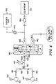
- FIG. 6 A schematic diagram of the gas flow through the manifold assembly 140 is illustrated in Fig. 6.
- Check valves 186 are located within manifold block 142 and coupled to each tank 54 so that gas can flow only the direction of arrows 188.
- Both tanks 54 supply regulator 162 to reduce the pressure of tanks 54 from about 2200 psi to about 50-55 psi.
- Reduced pressure inlet aperture 168 supplies gas to a first inlet 186 of cross over valve 180.
- cross over valve 180 is a model number Y 125 IN-VA1 valve available from Humphrey.
- an adjustable flow control valve 190 mounted to the top wall 141 is coupled to an outlet 185 of cross over valve 180.
- An outlet from the adjustable valve 190 is coupled to an oxygen bag 192 on the cart 24.
- An outlet connector 184 is coupled to critical care equipment 193, such as ventilator 40.
- Valve 190 includes a rotatable actuator 194 for adjusting the gas flow rate through an outlet connector 196.
- a flow rate indicator 198 is also provided.
- Connector 196 is coupled to an oxygen bag 192 or other equipment.
- FIG. 7 illustrates the manifold assembly 140 for oxygen and includes the oxygen flow control valve 190
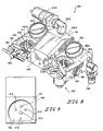
- Fig. 8 illustrates the manifold assembly 140 for air.
- the manifold block 142 of this invention may be made up of three separate blocks, 142A being the center block, 142B being the left block and 142C being the right block.
- the manifold block 142 is a single element.
- the three piece manifold block of the invention allows elements to be placed interior the manifold block 142, for example, the changeover valve 180.
- adjustable valve 190 on the oxygen manifold is mounted to the front wall 145 instead of the top wall 141.
- the regulator 162 in the invention is mounted to the bottom wall 143 instead of the front wall 145.
- the outlet connector 184 is connected to one of the side walls, 147 in Fig. 7 and 149 in Fig. 8.
- the second inlet coupler 182 is still connected to the bottom wall 143.
- a pressure switch 200 is connected by elbow 202 to the top wall 141 of the center manifold block 142A and is responsive to the pressure at an inlet 148 and at the same pressure as on the gauge 160.
- the pressure switch 200 may also be provided on the manifold of Figs. 3-6.
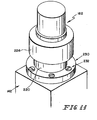
- the regulator 162 of the invention mates with planar surface 166 of the bottom wall 143 as illustrated in Fig. 9.
- the outlet aperture 150 of the manifold block 142 is connected to the inlet 164 of the regulator 162.
- the planar surface 166 also includes a plurality, for example, three threaded apertures 212.
- the apertures 212 and the inlet aperture 168 lie in a circle about the outlet aperture 150 in planar surface 166.
- the end wall 170 of the regulator has an outer annular seal 172, an inner annular seal 174 and an annular groove 176 formed between the inner and outer seals 172 and 174.
- An inlet 164 is encompassed by the inner seals 174.
- the seals 172 and 174 are located within annular notches formed in the end wall 170.
- An outlet aperture 178 (not shown) of the regulator 162 is formed in communication with the annular groove 176.
- Apertures 214 are spaced in the annular groove 176 and match with threaded apertures 212 in the planar surface 166.
- Fasteners 216 with lock washers 218 extend through aligned apertures 214 and 212 and mount the body 220 of the regulator 162 with the seals 172 and 174 to the manifold block 142A at surface 166.
- a filter 222 is shown received in the outlet aperture 150 of the manifold 142A.
- a threaded surface 224 of the regulator body 220 receives a bonnet assembly 226 which covers the fasteners 216.
- a diaphragm 227 resides in the bonnet assembly 226.
- apertures 212 in surface 166 and apertures 214 in the regulator are equally spaced about the annular groove 176.
- the regulator outlet aperture 178 does not have to align with the block inlet aperture 168 because of the annular groove 176.
- FIG. 11 Another arrangement for mounting the regulator 162 to the manifold block 142 not forming part of the present invention is illustrated in Fig. 11.
- a flange 230 is provided on the regulator body 220.
- Fasteners 232 extend through the flange 230 and are threadably received in the manifold 142.
- the alignment of the fasteners 232 may be similar to the alignment of fasteners 216 of Fig. 10 or may be any alignment since they are exterior the concentric annular seals 172 and 174.
- the end wall 170 of the regulator 162 would include the annular groove 176 having an outlet 178 and a centered inlet 164.
- the mounting fasteners are external the bonnet and therefore does not require disassembly of the bonnet 226 for mounting the regulator to the manifold.
- a pair of tank support platforms 201 are provided for supporting tanks 54.
- a spring 203 is located beneath each platform 201.
- Springs 203 are supported by a rigid support 204.
- the spring-loaded platforms 201 facilitate adjustment of the position of tanks 54 on the cart 24.
- the spring loaded platforms 201 facilitate adjustment of the tanks 54 so that an outlet of stems 158 is aligned with the inlets 148 of manifold block 142. Therefore, the tanks 154 can be loaded onto spring-loaded platforms 201 and then adjusted in the direction of doubleheaded arrow 207 to align the outlet of stems 158 with the inlets 148 of the manifold block 142.
- tanks 54 are loaded on to the care cart 24.
- an actuator (not shown) is used to open a valve 208 on tanks 54 to permit gas flow from the tanks into the manifold block 142.
- gas is automatically supplied from tanks 54 through the manifold block 142 and cross over valve 180 to the critical care equipment 193.
- Regulator 162 reduces high pressure from the tanks 54 to a working pressure of the critical care equipment 193.
- Separate pressure gauges 60 are provided for each tank 54 to provide visual inspection of the remaining capacity within the tanks 54.
- Check valves 186 prevent gas flow from one tank 54 to the other tank 54.
- the inlet 182 of cross over valve 180 is coupled to a wall source gas supply.
- Gas supply from the wall sources shuttles the cross over valve 180 to stop flow of gas from the tanks 54 to the equipment 193.
- Gas supply from the wall outlet is immediately directed to the critical care equipment 193.
- Disconnecting the wall supply from the cross over valve 180 automatically allows gas flow from the tanks 54 to the critical care equipment 193, provided that the tank valves 208 are open.
- the oxygen flow control valve 190 delivers oxygen flow to the oxygen bag 192 when the valve 180 receives a gas supply from either the wall gas source or the tanks 54.
Landscapes
- Health & Medical Sciences (AREA)
- Veterinary Medicine (AREA)
- Life Sciences & Earth Sciences (AREA)
- Animal Behavior & Ethology (AREA)
- General Health & Medical Sciences (AREA)
- Public Health (AREA)
- Nursing (AREA)
- Engineering & Computer Science (AREA)
- Biomedical Technology (AREA)
- Pulmonology (AREA)
- Emergency Medicine (AREA)
- Anesthesiology (AREA)
- Heart & Thoracic Surgery (AREA)
- Hematology (AREA)
- Valve Housings (AREA)
- Accommodation For Nursing Or Treatment Tables (AREA)
- Filling Or Discharging Of Gas Storage Vessels (AREA)
Description
Claims (18)
- A manifold assembly (140) comprising:a manifold block (142) having a first inlet (148), a first outlet (184), a planar surface (166), a second inlet (168) formed in the planar surface (166), and a second outlet (150) formed in the planar surface (166), the first inlet (148) being in gas flow communication with the second outlet (150), the second inlet (168) being in gas flow communication with the first outlet (184),a regulator (162) mounted to the manifold block (142) at the planar surface (166) and including a third inlet (164) and a third outlet (178) on a common end wall (170) of the regulator (162), the third inlet (164) being in gas flow communication with the second outlet (150), the third outlet (178) being in gas flow communication with the second inlet (168),a first annular seal (174) interposed between the manifold block (142) and the regulator (162), the first annular seal (174) having a first diameter, anda second annular seal (172) interposed between the manifold block (142) and the regulator (162), the second annular seal (172) having a second diameter that is larger than the first diameter, the second outlet (150) and the third inlet (164) both being positioned to lie radially inwardly of the second annular seal (172) and radially inwardly of the first annular seal (174), the second inlet (168) and the third outlet (178) both being positioned to lie radially outwardly of the first annular seal (174) and radially inwardly of the second annular seal (172), and characterised in thata fastener (216) couples the regulator (162) to the manifold block (142) which is positioned to lie radially outwardly of the first annular seal (174) and radially inwardly of the second annular seal (172).
- The manifold assembly according to claim I wherein one of the third inlet (164) and third outlet (178), (176) is annular.
- The manifold assembly of claim 1 or claim 2 further including first and second annular notches formed in the end wall of the regulator, and wherein the first and second seals (174), (172) are O-ring seals located within said first and second annular notches.
- The manifold assembly of any one of claims 1 to 3 including a filter (222) interposed between the second outlet (150) and the third inlet (164).
- The manifold assembly of any one of the preceding claims including a plurality of threaded fasteners (216) coupling the regulator (162) to the manifold block (142) and being positioned to lie radially outwardly of the first annular seal (174) and radially inwardly of the second annular seal (172).
- The manifold assembly according to claim 5 wherein the third outlet (178) and the plurality of fasteners (216) lie generally on a circle which encompasses the third inlet (164).
- The manifold assembly of any one of the preceding claims wherein the regulator (162) includes a body and a bonnet (226) threadably mounted on the body, and the bonnet (226) covers the fastener.
- The manifold assembly of claim 1 wherein the manifold block (142) has top (141), bottom (143) and side walls (145-149), and the planar surface (166) is on a side wall (145) of the manifold block (142).
- The manifold assembly of claim 8 wherein the first inlet (148) is on the same side wall (145) as the planar surface (166).
- The manifold assembly of claim 8 or 9 wherein the first outlet 184 is on the bottom wall (143).
- The manifold assembly of any one of claims 8 to 10 including a fourth gas outlet on the top wall (141).
- The manifold assembly of claim 1 wherein the manifold block has top (141), bottom (143) and side walls (145-149), and the planar surface (166) is on the bottom wall (143).
- The manifold assembly of claim 12 wherein the first inlet (148) is on a side wall of the manifold block (142).
- The manifold assembly of claim 9 or claim 13 including a fourth gas inlet on the bottom wall (143).
- The manifold assembly of claim 13, wherein the first outlet (184) is on another side wall.
- The manifold assembly of any one of claims 12 to 15 including a fourth gas outlet on the same side wall as the first inlet (148).
- The manifold assembly of claim 12 wherein the first outlet (184) is on a side wall.
- The manifold assembly of claim 17 including a fourth gas outlet on another side wall.
Applications Claiming Priority (3)
| Application Number | Priority Date | Filing Date | Title |
|---|---|---|---|
| US09/318,125 US6325097B1 (en) | 1997-01-31 | 1999-05-25 | Manifold and regulator apparatus |
| US318125 | 1999-05-25 | ||
| PCT/US2000/014566 WO2000071193A1 (en) | 1999-05-25 | 2000-05-25 | Manifold and regulator apparatus |
Publications (2)
| Publication Number | Publication Date |
|---|---|
| EP1181071A1 EP1181071A1 (en) | 2002-02-27 |
| EP1181071B1 true EP1181071B1 (en) | 2005-03-02 |
Family
ID=23236767
Family Applications (1)
| Application Number | Title | Priority Date | Filing Date |
|---|---|---|---|
| EP00937825A Expired - Lifetime EP1181071B1 (en) | 1999-05-25 | 2000-05-25 | Manifold and regulator apparatus |
Country Status (7)
| Country | Link |
|---|---|
| US (2) | US6325097B1 (en) |
| EP (1) | EP1181071B1 (en) |
| JP (1) | JP2003500120A (en) |
| AU (1) | AU5294800A (en) |
| CA (1) | CA2375174A1 (en) |
| DE (1) | DE60018410T2 (en) |
| WO (1) | WO2000071193A1 (en) |
Families Citing this family (21)
| Publication number | Priority date | Publication date | Assignee | Title |
|---|---|---|---|---|
| US6647982B1 (en) * | 1998-06-29 | 2003-11-18 | Zaiser Lenoir E. | Gas flow device |
| US6722388B1 (en) * | 2000-02-28 | 2004-04-20 | Mcaden Robert A. | Multiple pressure regulator |
| AU2002309987A1 (en) * | 2001-05-25 | 2002-12-09 | Hill-Rom Services, Inc. | Modular patient room |
| US6789563B2 (en) | 2002-06-04 | 2004-09-14 | Maxon Corporation | Pneumatic exhaust controller |
| US6805328B2 (en) | 2002-06-04 | 2004-10-19 | Maxon Corporation | Shut-off valve apparatus |
| US20040194829A1 (en) * | 2002-09-19 | 2004-10-07 | Zaiser Lenoir E. | Differential pressure valve employing near-balanced pressure |
| CA2456588A1 (en) * | 2003-04-09 | 2004-10-09 | J. Sterling Industries Ltd. | Chair conversion device |
| US7617826B1 (en) | 2004-02-26 | 2009-11-17 | Ameriflo, Inc. | Conserver |
| US8146592B2 (en) | 2004-02-26 | 2012-04-03 | Ameriflo, Inc. | Method and apparatus for regulating fluid flow or conserving fluid flow |
| US7448594B2 (en) | 2004-10-21 | 2008-11-11 | Ameriflo, Inc. | Fluid regulator |
| US7464710B2 (en) * | 2005-06-08 | 2008-12-16 | Norgren, Inc. | Manifold assembly for a ventilator system |
| US7857354B2 (en) * | 2006-05-19 | 2010-12-28 | Lifespan Healthcare, Llc, A Florida Limited Liability Company | Component-based utility supply apparatus |
| PT2009334E (en) * | 2007-06-26 | 2010-11-23 | Air Liquide Sanita Service S P A | Sectional valve or vacuum network with emergency intake |
| WO2011100135A1 (en) | 2010-02-11 | 2011-08-18 | Herman Miller, Inc. | Wall mounted assembly |
| US8713728B2 (en) * | 2010-07-30 | 2014-05-06 | Hill-Rom Services, Inc. | Medical gas tank holder for patient support apparatus |
| US9237979B2 (en) * | 2011-04-11 | 2016-01-19 | Hill-Rom Services, Inc. | Gas distribution assembly |
| WO2012160477A1 (en) * | 2011-05-20 | 2012-11-29 | Koninklijke Philips Electronics N.V. | Rotating electrical connector and respiratory gas delivery system employing same |
| KR101797372B1 (en) | 2016-07-11 | 2017-11-14 | 동양미래대학교 산학협력단 | Medical Gas Auto Manifold System |
| US10437268B2 (en) * | 2017-08-30 | 2019-10-08 | The Esab Group Inc. | Hybrid flow and pressure regulation |
| US10890286B2 (en) | 2018-04-20 | 2021-01-12 | Parker-Hannifin Corporation | Pressure regulated coupling manifold assembly |
| US20260132865A1 (en) * | 2024-11-14 | 2026-05-14 | Dennis E. Reid | Valve integrated pressure regulator (vipr) assembly with visual alert indicator |
Family Cites Families (38)
| Publication number | Priority date | Publication date | Assignee | Title |
|---|---|---|---|---|
| US3026079A (en) | 1960-04-04 | 1962-03-20 | Mary E Stack | Adjustable support means for liquid dispensing vessels |
| US3575205A (en) * | 1965-10-22 | 1971-04-20 | Robertshaw Controls Co | Pressure regulator construction |
| US4003584A (en) * | 1974-09-03 | 1977-01-18 | Sante Zelli | Dolly with articulated and steerable wheels |
| US4174733A (en) * | 1977-09-19 | 1979-11-20 | Fischer & Porter Company | Process gas flow control module |
| JPS5843626Y2 (en) * | 1978-07-25 | 1983-10-03 | アイシン精機株式会社 | Integrated valve set device |
| US4417648A (en) | 1981-07-14 | 1983-11-29 | General Electric Company | Braking arrangement for vehicles |
| US4494572A (en) | 1982-09-30 | 1985-01-22 | Humphrey Products Company | Four-way poppet valve assembly |
| US4547092A (en) | 1984-02-21 | 1985-10-15 | Hamilton Industries | Accessory clamp for medical table |
| US4582089A (en) | 1984-10-31 | 1986-04-15 | General Screw Products Company | Valve manifold having a removable flange |
| US4646211A (en) | 1984-11-19 | 1987-02-24 | Hill-Rom Company, Inc. | Service outlet wall and rail system for use thereon |
| US4790610A (en) | 1986-08-26 | 1988-12-13 | Intermetro Industries Corporation | Medical emergency crash cart |
| JPS63135179A (en) | 1986-11-26 | 1988-06-07 | 立花 俊郎 | Subcataneous drug administration set |
| US5299338A (en) | 1988-01-15 | 1994-04-05 | Hill-Rom Company, Inc. | Hospital bed with pivoting headboard |
| US5072906A (en) | 1988-01-15 | 1991-12-17 | Hill-Rom Company, Inc. | Hospital bed with pivoting headboard |
| US5060425A (en) | 1988-06-17 | 1991-10-29 | Hill-Rom Company, Inc. | Head wall for hospital bed |
| US4821470A (en) | 1988-06-17 | 1989-04-18 | Hill-Rom Company, Inc. | Head wall for hospital bed |
| US5137003A (en) * | 1989-05-19 | 1992-08-11 | Mitsubishi Denki K.K. | Supercharged pressure control valve apparatus |
| DE3917892C1 (en) * | 1989-06-01 | 1990-12-06 | F.M.K. Kreuzer Gmbh & Co Kg, 8039 Puchheim, De | |
| US5370111A (en) | 1990-05-16 | 1994-12-06 | Hill-Rom Company, Inc. | Mobile ventilator capable of nesting within and docking with a hospital bed base |
| US5335651A (en) * | 1990-05-16 | 1994-08-09 | Hill-Rom Company, Inc. | Ventilator and care cart each capable of nesting within and docking with a hospital bed base |
| US5337845A (en) | 1990-05-16 | 1994-08-16 | Hill-Rom Company, Inc. | Ventilator, care cart and motorized transport each capable of nesting within and docking with a hospital bed base |
| US5117521A (en) | 1990-05-16 | 1992-06-02 | Hill-Rom Company, Inc. | Care cart and transport system |
| FR2669199A1 (en) * | 1990-11-19 | 1992-05-22 | Peuret Daniel | Mobile projection cabinet |
| US5186337A (en) | 1991-08-09 | 1993-02-16 | Hill-Rom Company, Inc. | Pivoted power column |
| US5344169A (en) * | 1992-01-27 | 1994-09-06 | Pryor Products | Multi-pole support stand |
| US5299773A (en) | 1992-07-16 | 1994-04-05 | Ruston Bertrand | Mounting assembly for a pole |
| US5492146A (en) * | 1992-09-02 | 1996-02-20 | Richards Industries, Inc. | Pressure regulators |
| GB9309720D0 (en) | 1993-05-12 | 1993-06-23 | British Nuclear Fuels Plc | Measuring fluid flow rate |
| ES2145244T3 (en) | 1994-05-26 | 2000-07-01 | Flowtec Ag | MASS FLOW DETECTOR ACCORDING TO THE PRINCIPLE OF CORIOLIS. |
| US5725024A (en) | 1995-09-11 | 1998-03-10 | Pgi International, Ltd. | Manifold valve having controlled vent port integral with flange |
| US5598869A (en) | 1995-11-30 | 1997-02-04 | Robertshaw Controls Company | Pressure regulating unit |
| US5711340A (en) | 1996-01-16 | 1998-01-27 | The Esab Group, Inc. | Gas pressure reducing regulator |
| US5720317A (en) | 1996-08-21 | 1998-02-24 | Pgi International, Ltd. | Low profile flanged manifold valve |
| US5836355A (en) * | 1996-12-03 | 1998-11-17 | Insync Systems, Inc. | Building blocks for integrated gas panel |
| US5681116A (en) | 1996-12-17 | 1997-10-28 | Lin; Chin-Chih | Sliding track assembly |
| US5966760A (en) | 1997-01-31 | 1999-10-19 | Hill-Rom, Inc. | Apparatus and method for upgrading a hospital room |
| DE29805019U1 (en) * | 1998-03-19 | 1998-05-07 | Kreuzer Gmbh + Co Ohg, 82178 Puchheim | Monitoring and care facility for patients |
| US6003555A (en) | 1998-10-30 | 1999-12-21 | Sheng; Chih-Sheng | Structure of a pressure regulator |
-
1999
- 1999-05-25 US US09/318,125 patent/US6325097B1/en not_active Expired - Fee Related
-
2000
- 2000-05-25 DE DE60018410T patent/DE60018410T2/en not_active Expired - Fee Related
- 2000-05-25 EP EP00937825A patent/EP1181071B1/en not_active Expired - Lifetime
- 2000-05-25 WO PCT/US2000/014566 patent/WO2000071193A1/en not_active Ceased
- 2000-05-25 JP JP2000619494A patent/JP2003500120A/en active Pending
- 2000-05-25 AU AU52948/00A patent/AU5294800A/en not_active Abandoned
- 2000-05-25 CA CA002375174A patent/CA2375174A1/en not_active Abandoned
-
2001
- 2001-10-09 US US09/973,653 patent/US6382242B1/en not_active Expired - Fee Related
Also Published As
| Publication number | Publication date |
|---|---|
| WO2000071193A1 (en) | 2000-11-30 |
| JP2003500120A (en) | 2003-01-07 |
| DE60018410T2 (en) | 2005-07-21 |
| DE60018410D1 (en) | 2005-04-07 |
| AU5294800A (en) | 2000-12-12 |
| EP1181071A1 (en) | 2002-02-27 |
| US20020029805A1 (en) | 2002-03-14 |
| US6382242B1 (en) | 2002-05-07 |
| CA2375174A1 (en) | 2000-11-30 |
| US6325097B1 (en) | 2001-12-04 |
Similar Documents
| Publication | Publication Date | Title |
|---|---|---|
| US6325097B1 (en) | Manifold and regulator apparatus | |
| US6360389B1 (en) | Apparatus and method for upgrading a hospital room | |
| AU2002300758B2 (en) | Gas cylinder cart with removable control panel | |
| AU2008201525B2 (en) | Mobile functional hospital unit for the temporary distribution of medical fluids | |
| AU652631B2 (en) | Fluid filled flotation mattress | |
| CA3033008C (en) | Air cylinder cart with manifold for supplying one or two control panels | |
| WO1993015345A1 (en) | Fluid outlet system | |
| CA2725913C (en) | Mobile gas supply system | |
| US9560459B2 (en) | Modular voice amplification system for protective mask | |
| US8402965B1 (en) | Mass oxygen distribution system | |
| US20080011299A1 (en) | Medical gas delivery method and apparatus | |
| US6305400B1 (en) | Medical gas emergency delivery system and method | |
| AU2005271314A1 (en) | Fluid storage and delivery apparatus | |
| CA2221438C (en) | Replaceable flow-control assembly for use in a fluid flow line | |
| JP3204294U (en) | Worker safety support system in hazardous environment | |
| AU4243302A (en) | Apparatus and method for upgrading a hospital room | |
| US20230019321A1 (en) | Gas supply warning and communication system with super enriched oxygen generator | |
| WO2020117477A1 (en) | Mobile air supply cart | |
| CN121081863A (en) | Configurable flow regulator | |
| WO1997038742A1 (en) | Combined suction and gas delivery apparatus |
Legal Events
| Date | Code | Title | Description |
|---|---|---|---|
| PUAI | Public reference made under article 153(3) epc to a published international application that has entered the european phase |
Free format text: ORIGINAL CODE: 0009012 |
|
| 17P | Request for examination filed |
Effective date: 20011130 |
|
| AK | Designated contracting states |
Kind code of ref document: A1 Designated state(s): AT BE CH CY DE DK ES FI FR GB GR IE IT LI LU MC NL PT SE |
|
| AX | Request for extension of the european patent |
Free format text: AL;LT;LV;MK;RO;SI |
|
| RAP1 | Party data changed (applicant data changed or rights of an application transferred) |
Owner name: HILL-ROM SERVICES, INC. |
|
| 17Q | First examination report despatched |
Effective date: 20031027 |
|
| RBV | Designated contracting states (corrected) |
Designated state(s): DE FR GB IT |
|
| GRAP | Despatch of communication of intention to grant a patent |
Free format text: ORIGINAL CODE: EPIDOSNIGR1 |
|
| GRAS | Grant fee paid |
Free format text: ORIGINAL CODE: EPIDOSNIGR3 |
|
| GRAA | (expected) grant |
Free format text: ORIGINAL CODE: 0009210 |
|
| AK | Designated contracting states |
Kind code of ref document: B1 Designated state(s): DE FR GB IT |
|
| PG25 | Lapsed in a contracting state [announced via postgrant information from national office to epo] |
Ref country code: IT Free format text: LAPSE BECAUSE OF FAILURE TO SUBMIT A TRANSLATION OF THE DESCRIPTION OR TO PAY THE FEE WITHIN THE PRESCRIBED TIME-LIMIT;WARNING: LAPSES OF ITALIAN PATENTS WITH EFFECTIVE DATE BEFORE 2007 MAY HAVE OCCURRED AT ANY TIME BEFORE 2007. THE CORRECT EFFECTIVE DATE MAY BE DIFFERENT FROM THE ONE RECORDED. Effective date: 20050302 |
|
| REG | Reference to a national code |
Ref country code: GB Ref legal event code: FG4D |
|
| REG | Reference to a national code |
Ref country code: IE Ref legal event code: FG4D |
|
| REF | Corresponds to: |
Ref document number: 60018410 Country of ref document: DE Date of ref document: 20050407 Kind code of ref document: P |
|
| PGFP | Annual fee paid to national office [announced via postgrant information from national office to epo] |
Ref country code: FR Payment date: 20050517 Year of fee payment: 6 |
|
| PGFP | Annual fee paid to national office [announced via postgrant information from national office to epo] |
Ref country code: GB Payment date: 20050518 Year of fee payment: 6 |
|
| PGFP | Annual fee paid to national office [announced via postgrant information from national office to epo] |
Ref country code: DE Payment date: 20050630 Year of fee payment: 6 |
|
| ET | Fr: translation filed | ||
| PLBE | No opposition filed within time limit |
Free format text: ORIGINAL CODE: 0009261 |
|
| STAA | Information on the status of an ep patent application or granted ep patent |
Free format text: STATUS: NO OPPOSITION FILED WITHIN TIME LIMIT |
|
| 26N | No opposition filed |
Effective date: 20051205 |
|
| PG25 | Lapsed in a contracting state [announced via postgrant information from national office to epo] |
Ref country code: GB Free format text: LAPSE BECAUSE OF NON-PAYMENT OF DUE FEES Effective date: 20060525 |
|
| PG25 | Lapsed in a contracting state [announced via postgrant information from national office to epo] |
Ref country code: DE Free format text: LAPSE BECAUSE OF NON-PAYMENT OF DUE FEES Effective date: 20061201 |
|
| GBPC | Gb: european patent ceased through non-payment of renewal fee |
Effective date: 20060525 |
|
| REG | Reference to a national code |
Ref country code: FR Ref legal event code: ST Effective date: 20070131 |
|
| PG25 | Lapsed in a contracting state [announced via postgrant information from national office to epo] |
Ref country code: FR Free format text: LAPSE BECAUSE OF NON-PAYMENT OF DUE FEES Effective date: 20060531 |