EP1180861A2 - Optical Wavelength Division Multiplexed transmission system - Google Patents
Optical Wavelength Division Multiplexed transmission system Download PDFInfo
- Publication number
- EP1180861A2 EP1180861A2 EP01306447A EP01306447A EP1180861A2 EP 1180861 A2 EP1180861 A2 EP 1180861A2 EP 01306447 A EP01306447 A EP 01306447A EP 01306447 A EP01306447 A EP 01306447A EP 1180861 A2 EP1180861 A2 EP 1180861A2
- Authority
- EP
- European Patent Office
- Prior art keywords
- osnr
- power
- fwm
- amplifier
- link
- Prior art date
- Legal status (The legal status is an assumption and is not a legal conclusion. Google has not performed a legal analysis and makes no representation as to the accuracy of the status listed.)
- Granted
Links
Images


Classifications
-
- H—ELECTRICITY
- H04—ELECTRIC COMMUNICATION TECHNIQUE
- H04B—TRANSMISSION
- H04B10/00—Transmission systems employing electromagnetic waves other than radio-waves, e.g. infrared, visible or ultraviolet light, or employing corpuscular radiation, e.g. quantum communication
- H04B10/29—Repeaters
- H04B10/291—Repeaters in which processing or amplification is carried out without conversion of the main signal from optical form
- H04B10/293—Signal power control
- H04B10/294—Signal power control in a multiwavelength system, e.g. gain equalisation
- H04B10/296—Transient power control, e.g. due to channel add/drop or rapid fluctuations in the input power
Definitions
- This invention relates to an optical transmission system in which communication signals are sent over a common optical fibre path at different wavelengths, or colours.
- Such a system is termed wavelength division multiplex (WDM), and it permits efficient use of an optical fibre path.
- WDM wavelength division multiplex
- Fibre group velocity dispersion was the most significant problem when single channel systems, operating near the minimum of fibre attenuation (about 1550 nm), were introduced some years ago. To overcome this problem, dispersion-shifted fibres were designed, having the minimum of group velocity dispersion occurring near 1550 nm. Fibre of this kind has been widely installed for optical transport networks. The introduction of the optical amplifier and progresses in lasers manufacturing now makes it possible to carry many high bit-rate channels on very long distances at different wavelengths (WDM). Unfortunately non-linear fibre behaviour is significant at high powers boosted into the fibre by optical amplifiers and has a big impact on bit error rates (BER) performances, giving rise to cross talk among channels.
- WDM wavelengths
- the present invention seeks to provide a method of operating an optical transmission system in a more efficient manner.
- a method of determining the launch power of a WDM optical transmission system having a plurality of sequential amplified spans which together form a link includes the step of setting the amplifier power at each amplifier at or near the same maximum value at which both the optical signal to noise ratio due to amplified spontaneous emission (OSNR ase ) and the optical signal to noise ratio due to four wave mixing (OSNR fwm ) each are above respective predetermined threshold values at the end of the link.
- OSNR ase amplified spontaneous emission
- OSNR fwm four wave mixing
- OSNR ase and OSNR fwm are inter-related, and preferably an iterative process is used to determine the optimum maximum launch power which does not give rise to an unacceptably high bit error rate.
- a method of determining the launch power of a WDM optical transmission system having an amplified link includes the steps of
- the link includes a plurality of sequential amplified spans, in which case preferably each amplifier power is at the same value.
- the WDM optical transmission system consists of an optical transmitter arrangement 1 which transmits a WDM optical signal over a link consisting of three spans 2, 3, 4 to an optical receiver arrangement 5.
- the transmitter arrangement has a number of individual optical signal transmitters 6, each generating an optical channel signal at a different wavelength. These channel signals are sent over fibres 7 of a multiplexer 8 where they are combined, whilst preserving the carrier wavelength of each channel, and are launched by a high power amplifier 9 over the optical fibre which comprises the first span 2.
- Optical amplifiers 10 and 11 amplify the optical signals for onward transmission over spans 3 and 4 respectively for reception at receiver arrangement 5.
- An input amplifier 12 amplifies the received optical channels prior to them being demultiplexed, ie separated out, by demultiplexer 13 and sent over separate fibres 14, each of which carries a single optical channel, to respective receivers 15.
- the received optical signal is monitored by an OSNR monitor 20 which calculates the values of OSNR ase and OSNR fwm . These values are compared at comparators 21 and 22 with respective threshold values of OSNR ase and OSNR fwm which represent the minimum acceptable values for the link. The results of the comparisons are passed to an amplifier control unit 23, which acts to adjust the amplifier power of amplifiers 9, 10 and 11.
- the cross talk is an important impairment in WDM systems and it can be shown that it rises when fibre dispersion is low, as happens in dispersion shifted fibres and it is proportional to the third power of channels power.
- a currently applied solution to avoid FWM cross talk is to arrange the channel frequencies so that no mixing product falls on any of the channels. This condition can be satisfied only if the channels are unequally spaced.
- the use of unequal channel spacing required a greater bandwidth than for equally spaced channels for a given number of channels.
- the invention allows carrying a number of channels greater than that which is apparent from a consideration of the FWM effect, using the same amplifiers on standard systems, without the need to change transmitting and optical filter specifications.
- OSNR (OSNR ase -1 + OSNR fwm -1 ) -1
- total transmission line consists of M sections and (M-1) in-line amplifiers.
- the repeater span is equal throughout the transmission: this is a good approximation, because the FWM is efficient only in first kilometres of each span, where channel power is higher. Thus it is not dependent on span length.
- the gain of each amplifier is adjusted to compensate the transmission loss of the section just before the amplifier: this is the actual situation, when all amplifiers are working in saturation regime.
- the signal power output from an in-line amplifier i.e., fibre input power
- One section consists of N fibre lengths with different zero-dispersion wavelength, which is assumed to be uniform along one length. The length of each fibre is equal.
- the polarisation states of each light are assumed to be matched throughout the transmission.
- the final FWM power is:
- f 0 (mn) are modelled as random variables gaussian distributed.
- P fwm also will be a random variable whose distribution can be found using a Montecarlo procedure.
- the OSNR fwm relative to the m-th channel will be:
- Both NF and G depend on the wavelength and on the total input power.
Landscapes
- Physics & Mathematics (AREA)
- Electromagnetism (AREA)
- Engineering & Computer Science (AREA)
- Computer Networks & Wireless Communication (AREA)
- Signal Processing (AREA)
- Optical Communication System (AREA)
- Lasers (AREA)
Abstract
Description


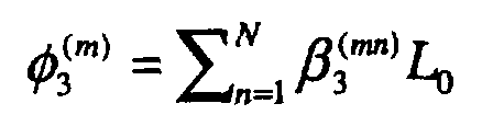
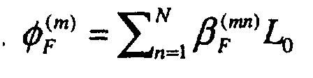


- P(m) is the power of the m-th channel
- Pfwm (i,j,k) is the FWM power generated by channels i-th, j-th and k-th, calculated
according to

- ASE is the Amplified Spontaneous Emission noise power (W);
- h is the Planck's constants (J·s);
- f0 is the working frequency (Hz);
- NF is the optical amplifier noise figure;
- G is the optical amplifier gain;
- Mt is the number of polarisation states (Mt = 1 or 2);
- Bo is the optical bandwidth (Hz).
- Si is the channel power in dBm after the i-th optical line amplifier (i= 1, ..., n-1);
- S0 is the channel power in dBm after the launch booster;
- Sn is the channel power in dBm after the final preamplifier ;
- Ni is the noise power in dBm after the i-th optical line amplifier on a Bo bandwidth around one channel (i= 1, ..., n-1);
- N0 is the Noise signal power in dBm per channel generated by the booster, calculated
as in
Equation 4; - Nn is the Noise power in dBm per channel after the final preamplifier;
- ASEi is the noise generated by the i-th amplifier, calculated as in
Equation 4; - Li is the i-th span Loss (in dB);
- Gi{.} is the i-th optical amplifier Gain in dB, as a function of the total input power;
- n is the number of spans.
Claims (5)
- A method of determining the launch power of a WDM optical transmission system having a plurality of sequential amplified spans which together form a link including the step of setting the amplifier power at each amplifier at or near the same maximum value at which both the optical signal to noise ratio due to amplified spontaneous emission (OSNRase) and the optical signal to noise ratio due to four wave mixing (OSNRfwm) each are above respective predetermined threshold values at the end of the link.
- A method as claimed in Claim 1 and wherein an iterative process is used to determine the optimum maximum launch power which does not give rise to an unacceptably high bit error rate.
- A method of determining the launch power of a WDM optical transmission system having an amplified link including the steps of(a) setting the amplifier power at the beginning of the link,(b) determining the signal to noise ratio due to amplified spontaneous emission (OSNRase) and the optical signal to noise ratio due to four wave mixing (OSNRfwm) at the end of the link,(c) comparing each of OSNRase and OSNRfwm with a respective predetermined threshold value,(d) altering the amplifier power,(e) repeating steps (b), (c) and (d) until the amplifier power is at or near a maximum value whilst both OSNRase and OSNRfwm exceed the respective threshold values.
- A method as claimed in Claim 3 and wherein the link includes a plurality of sequential amplified spans, and step (d) is performed on each amplifier at the start of a link.
- A method as claimed in Claim 4 and wherein the amplified power launched into each span is at the same value.
Applications Claiming Priority (2)
| Application Number | Priority Date | Filing Date | Title |
|---|---|---|---|
| ITTO000808 | 2000-08-18 | ||
| IT2000TO000808A IT1320596B1 (en) | 2000-08-18 | 2000-08-18 | OPTICAL TRANSMISSION SYSTEM. |
Publications (3)
| Publication Number | Publication Date |
|---|---|
| EP1180861A2 true EP1180861A2 (en) | 2002-02-20 |
| EP1180861A3 EP1180861A3 (en) | 2003-12-17 |
| EP1180861B1 EP1180861B1 (en) | 2007-06-06 |
Family
ID=11458004
Family Applications (1)
| Application Number | Title | Priority Date | Filing Date |
|---|---|---|---|
| EP01306447A Expired - Lifetime EP1180861B1 (en) | 2000-08-18 | 2001-07-27 | Method of determining the launch power of an optical wavelength division multiplexed transmission system |
Country Status (10)
| Country | Link |
|---|---|
| US (1) | US6657779B2 (en) |
| EP (1) | EP1180861B1 (en) |
| JP (1) | JP2002141868A (en) |
| AT (1) | ATE364264T1 (en) |
| AU (1) | AU6187601A (en) |
| DE (1) | DE60128756T2 (en) |
| IT (1) | IT1320596B1 (en) |
| NO (1) | NO20013999L (en) |
| RU (1) | RU2001123251A (en) |
| ZA (1) | ZA200106216B (en) |
Cited By (2)
| Publication number | Priority date | Publication date | Assignee | Title |
|---|---|---|---|---|
| WO2003050983A1 (en) * | 2001-12-12 | 2003-06-19 | Marconi Uk Intellectual Property Ltd | Signal transmission apparatus and a method of signal transmission |
| EP3376687A1 (en) * | 2017-03-17 | 2018-09-19 | Xieon Networks S.à r.l. | Determination of channel osnr and channel osnr margin at real network conditions |
Families Citing this family (9)
| Publication number | Priority date | Publication date | Assignee | Title |
|---|---|---|---|---|
| WO2002091027A2 (en) * | 2001-05-09 | 2002-11-14 | Ciena Corporation | Method and system for controlling amplifier power in an optical communications network having add/drop capability |
| US6600596B2 (en) | 2001-05-09 | 2003-07-29 | Ciena Corporation | Method and system for controlling amplifier power in an optical communications network having add/drop capability |
| JP2003124881A (en) * | 2001-10-15 | 2003-04-25 | Fujitsu Ltd | Optical transmission device and optical transmission system |
| JP3971935B2 (en) * | 2002-02-12 | 2007-09-05 | 株式会社日立コミュニケーションテクノロジー | Optical transmission device and optical transmission system capable of reducing transmission quality degradation due to four-wave mixing |
| JP3934513B2 (en) * | 2002-08-29 | 2007-06-20 | 富士通株式会社 | Pre-emphasis control method considering nonlinear degradation |
| US7379647B2 (en) * | 2005-09-29 | 2008-05-27 | Lucent Technologies Inc. | Configuring optical launch powers in optical fiber transmission lines |
| JP5267899B2 (en) * | 2007-03-28 | 2013-08-21 | 日本電気株式会社 | Wavelength division multiplexing optical transmission system and wavelength division multiplexing optical transmission method |
| JP5396829B2 (en) * | 2008-11-21 | 2014-01-22 | 富士通株式会社 | Distributed Raman amplifier and optical communication system |
| JP6666645B2 (en) | 2014-05-16 | 2020-03-18 | 富士通株式会社 | Apparatus and method for measuring signal light quality |
Family Cites Families (9)
| Publication number | Priority date | Publication date | Assignee | Title |
|---|---|---|---|---|
| GB2272590B (en) * | 1992-11-17 | 1996-06-19 | Northern Telecom Ltd | Optical communications system |
| JPH06318754A (en) * | 1993-05-10 | 1994-11-15 | Matsushita Electric Ind Co Ltd | Optical fiber amplifier and optical signal transmission system |
| CA2155693C (en) * | 1994-08-25 | 1999-12-14 | Daniel A. Fishman | Performance monitoring and fault location in optical transmission systems |
| JPH09247091A (en) * | 1996-03-08 | 1997-09-19 | Fujitsu Ltd | Optical transmission device and optical transmission system |
| US6069718A (en) * | 1997-09-19 | 2000-05-30 | Nortel Networks Corporation | Distortion penalty measurement procedure in optical systems using noise loading |
| DE60022567T2 (en) * | 1999-04-01 | 2006-05-04 | Cisco Photonics Italy S.R.L. | Method for noise reduction in a remote optical telecommunication system |
| US6697558B2 (en) * | 2000-03-03 | 2004-02-24 | Fitel U.S.A. Corp | Raman amplified optical system with reduction of four-wave mixing effects |
| US6384963B2 (en) * | 2000-03-03 | 2002-05-07 | Lucent Technologies Inc. | Optical communication system with co-propagating pump radiation for raman amplification |
| US6643057B2 (en) * | 2001-02-26 | 2003-11-04 | Corning Incorporated | Optical amplifier with reduced non-linear signal impairments by optimum pumping configuration and method for using same |
-
2000
- 2000-08-18 IT IT2000TO000808A patent/IT1320596B1/en active
-
2001
- 2001-07-27 AT AT01306447T patent/ATE364264T1/en not_active IP Right Cessation
- 2001-07-27 ZA ZA200106216A patent/ZA200106216B/en unknown
- 2001-07-27 EP EP01306447A patent/EP1180861B1/en not_active Expired - Lifetime
- 2001-07-27 DE DE60128756T patent/DE60128756T2/en not_active Expired - Lifetime
- 2001-08-10 US US09/928,252 patent/US6657779B2/en not_active Expired - Lifetime
- 2001-08-16 JP JP2001247105A patent/JP2002141868A/en active Pending
- 2001-08-16 NO NO20013999A patent/NO20013999L/en unknown
- 2001-08-17 RU RU2001123251/09A patent/RU2001123251A/en not_active Application Discontinuation
- 2001-08-17 AU AU61876/01A patent/AU6187601A/en not_active Abandoned
Cited By (4)
| Publication number | Priority date | Publication date | Assignee | Title |
|---|---|---|---|---|
| WO2003050983A1 (en) * | 2001-12-12 | 2003-06-19 | Marconi Uk Intellectual Property Ltd | Signal transmission apparatus and a method of signal transmission |
| US7447441B2 (en) | 2001-12-12 | 2008-11-04 | Ericsson Ab | Signal transmission apparatus and a method of signal transmission |
| EP3376687A1 (en) * | 2017-03-17 | 2018-09-19 | Xieon Networks S.à r.l. | Determination of channel osnr and channel osnr margin at real network conditions |
| WO2018167325A1 (en) * | 2017-03-17 | 2018-09-20 | Xieon Networks S.À R.L. | Determination of channel osnr and channel osnr margin at real network conditions |
Also Published As
| Publication number | Publication date |
|---|---|
| EP1180861A3 (en) | 2003-12-17 |
| AU6187601A (en) | 2002-02-21 |
| JP2002141868A (en) | 2002-05-17 |
| DE60128756T2 (en) | 2008-01-31 |
| NO20013999D0 (en) | 2001-08-16 |
| NO20013999L (en) | 2002-02-19 |
| IT1320596B1 (en) | 2003-12-10 |
| ITTO20000808A1 (en) | 2002-02-18 |
| EP1180861B1 (en) | 2007-06-06 |
| US6657779B2 (en) | 2003-12-02 |
| ATE364264T1 (en) | 2007-06-15 |
| RU2001123251A (en) | 2003-06-27 |
| US20020044340A1 (en) | 2002-04-18 |
| DE60128756D1 (en) | 2007-07-19 |
| ZA200106216B (en) | 2002-01-31 |
| ITTO20000808A0 (en) | 2000-08-18 |
Similar Documents
| Publication | Publication Date | Title |
|---|---|---|
| US6885499B1 (en) | Optical amplifying apparatus for amplifying wide-wavelength-band light, optical sending apparatus, optical transmission system, and optical amplifying method | |
| US6636659B2 (en) | Optical amplification apparatus and optical transmission system | |
| JP2000244398A (en) | Method for realizing optical communication system | |
| US6771854B2 (en) | Optical transmission system and optical coupler/branching filter | |
| US20020159131A1 (en) | Optical amplifier providing dispersion compensation | |
| EP1180861B1 (en) | Method of determining the launch power of an optical wavelength division multiplexed transmission system | |
| JPH06258545A (en) | Optical demultiplexer | |
| JP3771010B2 (en) | Method for optical amplification and system for implementing the method | |
| JP2003524931A (en) | Multi-wavelength optical communication system with optical amplifier | |
| US5978122A (en) | Noise suppression method for wavelength division multiplexing transmission system | |
| US7057802B2 (en) | Optical amplifier device | |
| US7142782B2 (en) | Noise light elimination method, noise light elimination apparatus and optical transmission system, using stimulated brillouin scattering | |
| JP4234382B2 (en) | Optical amplification method, apparatus thereof, and optical amplification repeater system using the apparatus | |
| US20040146302A1 (en) | Channel power control method in WDM system | |
| KR20090007356A (en) | System and method for implementing a no-booster optical communication system | |
| US6798945B1 (en) | Lumped raman amplifier for adaptive dispersion compensation | |
| US8938145B2 (en) | Configuring optical launch powers in optical fiber transmission lines | |
| US6552845B2 (en) | Optical gain equalizer and optical fiber transmission line | |
| US7042632B2 (en) | Raman amplifier | |
| EP4170934A1 (en) | Method for reducing the impact of transient effects in an optical network | |
| JP2003264511A (en) | Optical amplification method, device therefor, and optical amplification repeater system using the device | |
| EP1972085B1 (en) | Optical communication network and method of routing in the network | |
| JP2000077757A (en) | Optical amplifier, optical transmission device, and optical transmission system | |
| US8121491B2 (en) | Method, apparatus and data carrier for compensating for channel depletion of a multi-channel signal in an optical link or optical network | |
| US20050200945A1 (en) | Optical fiber communication systems with brillouin effect amplification |
Legal Events
| Date | Code | Title | Description |
|---|---|---|---|
| PUAI | Public reference made under article 153(3) epc to a published international application that has entered the european phase |
Free format text: ORIGINAL CODE: 0009012 |
|
| AK | Designated contracting states |
Kind code of ref document: A2 Designated state(s): AT BE CH CY DE DK ES FI FR GB GR IE IT LI LU MC NL PT SE TR |
|
| AX | Request for extension of the european patent |
Free format text: AL;LT;LV;MK;RO;SI |
|
| PUAL | Search report despatched |
Free format text: ORIGINAL CODE: 0009013 |
|
| AK | Designated contracting states |
Kind code of ref document: A3 Designated state(s): AT BE CH CY DE DK ES FI FR GB GR IE IT LI LU MC NL PT SE TR |
|
| AX | Request for extension of the european patent |
Extension state: AL LT LV MK RO SI |
|
| RIC1 | Information provided on ipc code assigned before grant |
Ipc: 7H 04B 10/17 A Ipc: 7H 04B 10/08 B |
|
| 17P | Request for examination filed |
Effective date: 20040407 |
|
| AKX | Designation fees paid |
Designated state(s): AT BE CH CY DE DK ES FI FR GB GR IE IT LI LU MC NL PT SE TR |
|
| RAP1 | Party data changed (applicant data changed or rights of an application transferred) |
Owner name: ERICSSON AB |
|
| GRAP | Despatch of communication of intention to grant a patent |
Free format text: ORIGINAL CODE: EPIDOSNIGR1 |
|
| RTI1 | Title (correction) |
Free format text: METHOD OF DETERMINING THE LAUNCH POWER OF AN OPTICAL WAVELENGTH DIVISION MULTIPLEXED TRANSMISSION SYSTEM |
|
| RAP1 | Party data changed (applicant data changed or rights of an application transferred) |
Owner name: ERICSSON AB |
|
| GRAS | Grant fee paid |
Free format text: ORIGINAL CODE: EPIDOSNIGR3 |
|
| GRAA | (expected) grant |
Free format text: ORIGINAL CODE: 0009210 |
|
| AK | Designated contracting states |
Kind code of ref document: B1 Designated state(s): AT BE CH CY DE DK ES FI FR GB GR IE IT LI LU MC NL PT SE TR |
|
| PG25 | Lapsed in a contracting state [announced via postgrant information from national office to epo] |
Ref country code: LI Free format text: LAPSE BECAUSE OF FAILURE TO SUBMIT A TRANSLATION OF THE DESCRIPTION OR TO PAY THE FEE WITHIN THE PRESCRIBED TIME-LIMIT Effective date: 20070606 Ref country code: FI Free format text: LAPSE BECAUSE OF FAILURE TO SUBMIT A TRANSLATION OF THE DESCRIPTION OR TO PAY THE FEE WITHIN THE PRESCRIBED TIME-LIMIT Effective date: 20070606 Ref country code: CH Free format text: LAPSE BECAUSE OF FAILURE TO SUBMIT A TRANSLATION OF THE DESCRIPTION OR TO PAY THE FEE WITHIN THE PRESCRIBED TIME-LIMIT Effective date: 20070606 |
|
| REG | Reference to a national code |
Ref country code: GB Ref legal event code: FG4D |
|
| REG | Reference to a national code |
Ref country code: CH Ref legal event code: EP |
|
| REG | Reference to a national code |
Ref country code: IE Ref legal event code: FG4D |
|
| REF | Corresponds to: |
Ref document number: 60128756 Country of ref document: DE Date of ref document: 20070719 Kind code of ref document: P |
|
| PG25 | Lapsed in a contracting state [announced via postgrant information from national office to epo] |
Ref country code: SE Free format text: LAPSE BECAUSE OF FAILURE TO SUBMIT A TRANSLATION OF THE DESCRIPTION OR TO PAY THE FEE WITHIN THE PRESCRIBED TIME-LIMIT Effective date: 20070906 |
|
| PG25 | Lapsed in a contracting state [announced via postgrant information from national office to epo] |
Ref country code: ES Free format text: LAPSE BECAUSE OF FAILURE TO SUBMIT A TRANSLATION OF THE DESCRIPTION OR TO PAY THE FEE WITHIN THE PRESCRIBED TIME-LIMIT Effective date: 20070917 |
|
| ET | Fr: translation filed | ||
| PG25 | Lapsed in a contracting state [announced via postgrant information from national office to epo] |
Ref country code: AT Free format text: LAPSE BECAUSE OF FAILURE TO SUBMIT A TRANSLATION OF THE DESCRIPTION OR TO PAY THE FEE WITHIN THE PRESCRIBED TIME-LIMIT Effective date: 20070606 |
|
| NLV1 | Nl: lapsed or annulled due to failure to fulfill the requirements of art. 29p and 29m of the patents act | ||
| REG | Reference to a national code |
Ref country code: CH Ref legal event code: PL |
|
| PG25 | Lapsed in a contracting state [announced via postgrant information from national office to epo] |
Ref country code: BE Free format text: LAPSE BECAUSE OF FAILURE TO SUBMIT A TRANSLATION OF THE DESCRIPTION OR TO PAY THE FEE WITHIN THE PRESCRIBED TIME-LIMIT Effective date: 20070606 |
|
| PG25 | Lapsed in a contracting state [announced via postgrant information from national office to epo] |
Ref country code: NL Free format text: LAPSE BECAUSE OF FAILURE TO SUBMIT A TRANSLATION OF THE DESCRIPTION OR TO PAY THE FEE WITHIN THE PRESCRIBED TIME-LIMIT Effective date: 20070606 Ref country code: PT Free format text: LAPSE BECAUSE OF FAILURE TO SUBMIT A TRANSLATION OF THE DESCRIPTION OR TO PAY THE FEE WITHIN THE PRESCRIBED TIME-LIMIT Effective date: 20071106 |
|
| PLBE | No opposition filed within time limit |
Free format text: ORIGINAL CODE: 0009261 |
|
| STAA | Information on the status of an ep patent application or granted ep patent |
Free format text: STATUS: NO OPPOSITION FILED WITHIN TIME LIMIT |
|
| PG25 | Lapsed in a contracting state [announced via postgrant information from national office to epo] |
Ref country code: MC Free format text: LAPSE BECAUSE OF NON-PAYMENT OF DUE FEES Effective date: 20070731 Ref country code: DK Free format text: LAPSE BECAUSE OF FAILURE TO SUBMIT A TRANSLATION OF THE DESCRIPTION OR TO PAY THE FEE WITHIN THE PRESCRIBED TIME-LIMIT Effective date: 20070606 Ref country code: IT Free format text: LAPSE BECAUSE OF FAILURE TO SUBMIT A TRANSLATION OF THE DESCRIPTION OR TO PAY THE FEE WITHIN THE PRESCRIBED TIME-LIMIT Effective date: 20070606 Ref country code: GR Free format text: LAPSE BECAUSE OF FAILURE TO SUBMIT A TRANSLATION OF THE DESCRIPTION OR TO PAY THE FEE WITHIN THE PRESCRIBED TIME-LIMIT Effective date: 20070907 |
|
| 26N | No opposition filed |
Effective date: 20080307 |
|
| PG25 | Lapsed in a contracting state [announced via postgrant information from national office to epo] |
Ref country code: IE Free format text: LAPSE BECAUSE OF NON-PAYMENT OF DUE FEES Effective date: 20070727 |
|
| PG25 | Lapsed in a contracting state [announced via postgrant information from national office to epo] |
Ref country code: CY Free format text: LAPSE BECAUSE OF FAILURE TO SUBMIT A TRANSLATION OF THE DESCRIPTION OR TO PAY THE FEE WITHIN THE PRESCRIBED TIME-LIMIT Effective date: 20070606 |
|
| PG25 | Lapsed in a contracting state [announced via postgrant information from national office to epo] |
Ref country code: LU Free format text: LAPSE BECAUSE OF NON-PAYMENT OF DUE FEES Effective date: 20070727 |
|
| PG25 | Lapsed in a contracting state [announced via postgrant information from national office to epo] |
Ref country code: TR Free format text: LAPSE BECAUSE OF FAILURE TO SUBMIT A TRANSLATION OF THE DESCRIPTION OR TO PAY THE FEE WITHIN THE PRESCRIBED TIME-LIMIT Effective date: 20070606 |
|
| PGFP | Annual fee paid to national office [announced via postgrant information from national office to epo] |
Ref country code: DE Payment date: 20140729 Year of fee payment: 14 |
|
| PGFP | Annual fee paid to national office [announced via postgrant information from national office to epo] |
Ref country code: GB Payment date: 20140729 Year of fee payment: 14 Ref country code: FR Payment date: 20140717 Year of fee payment: 14 |
|
| REG | Reference to a national code |
Ref country code: DE Ref legal event code: R119 Ref document number: 60128756 Country of ref document: DE |
|
| GBPC | Gb: european patent ceased through non-payment of renewal fee |
Effective date: 20150727 |
|
| PG25 | Lapsed in a contracting state [announced via postgrant information from national office to epo] |
Ref country code: DE Free format text: LAPSE BECAUSE OF NON-PAYMENT OF DUE FEES Effective date: 20160202 Ref country code: GB Free format text: LAPSE BECAUSE OF NON-PAYMENT OF DUE FEES Effective date: 20150727 |
|
| REG | Reference to a national code |
Ref country code: FR Ref legal event code: ST Effective date: 20160331 |
|
| PG25 | Lapsed in a contracting state [announced via postgrant information from national office to epo] |
Ref country code: FR Free format text: LAPSE BECAUSE OF NON-PAYMENT OF DUE FEES Effective date: 20150731 |