EP1180845A2 - Vehicle rotary electric machine - Google Patents
Vehicle rotary electric machine Download PDFInfo
- Publication number
- EP1180845A2 EP1180845A2 EP01117875A EP01117875A EP1180845A2 EP 1180845 A2 EP1180845 A2 EP 1180845A2 EP 01117875 A EP01117875 A EP 01117875A EP 01117875 A EP01117875 A EP 01117875A EP 1180845 A2 EP1180845 A2 EP 1180845A2
- Authority
- EP
- European Patent Office
- Prior art keywords
- positive
- sacrificing
- conductor member
- metal member
- insulation
- Prior art date
- Legal status (The legal status is an assumption and is not a legal conclusion. Google has not performed a legal analysis and makes no representation as to the accuracy of the status listed.)
- Granted
Links
Images




Classifications
-
- H—ELECTRICITY
- H02—GENERATION; CONVERSION OR DISTRIBUTION OF ELECTRIC POWER
- H02K—DYNAMO-ELECTRIC MACHINES
- H02K5/00—Casings; Enclosures; Supports
- H02K5/04—Casings or enclosures characterised by the shape, form or construction thereof
- H02K5/22—Auxiliary parts of casings not covered by groups H02K5/06-H02K5/20, e.g. shaped to form connection boxes or terminal boxes
- H02K5/225—Terminal boxes or connection arrangements
-
- H—ELECTRICITY
- H02—GENERATION; CONVERSION OR DISTRIBUTION OF ELECTRIC POWER
- H02K—DYNAMO-ELECTRIC MACHINES
- H02K11/00—Structural association of dynamo-electric machines with electric components or with devices for shielding, monitoring or protection
- H02K11/20—Structural association of dynamo-electric machines with electric components or with devices for shielding, monitoring or protection for measuring, monitoring, testing, protecting or switching
-
- H—ELECTRICITY
- H02—GENERATION; CONVERSION OR DISTRIBUTION OF ELECTRIC POWER
- H02K—DYNAMO-ELECTRIC MACHINES
- H02K11/00—Structural association of dynamo-electric machines with electric components or with devices for shielding, monitoring or protection
- H02K11/04—Structural association of dynamo-electric machines with electric components or with devices for shielding, monitoring or protection for rectification
- H02K11/049—Rectifiers associated with stationary parts, e.g. stator cores
- H02K11/05—Rectifiers associated with casings, enclosures or brackets
-
- H—ELECTRICITY
- H02—GENERATION; CONVERSION OR DISTRIBUTION OF ELECTRIC POWER
- H02K—DYNAMO-ELECTRIC MACHINES
- H02K11/00—Structural association of dynamo-electric machines with electric components or with devices for shielding, monitoring or protection
- H02K11/40—Structural association with grounding devices
Definitions
- the present invention relates to a rectifier protection arrangement a vehicle rotary electric machine.
- a common rectifier unit is accommodated between a frame 100 and a metal cover 101 of a vehicle AC generator, as shown in Fig. 5.
- the rectifier unit is comprised of a bridge circuit of four positive rectifier elements 108 and four negative rectifier elements (not shown) and a terminal unit 104.
- the positive rectifier elements 108 are fixed to a positive fin 105 by soldering or press-fitting, and the negative rectifier elements (not shown) are also fixed to a negative fin 107 in the same manner as above.
- a metal terminal 110 is molded together with the terminal unit 104. An end of the metal terminal 110 is connected to a lead 109, and the other end is connected to a terminal of one of the rectifier elements 108.
- the molding material of the terminal unit 104 is thermoplastic resin such as polyphenylene sulfide, which is excellent in moldability, dimensional stability, heat resistance, and electric insulation.
- An insulation bush 106 is interposed between the positive fin 105 and negative fin 107 and does not require molding with a metal member such as the terminal unit 4.
- the insulation bush 106 is a simple cylindrical member made of an inexpensive thermosetting resin such as a phenol resin for providing a space between the two fins 105 and 107.
- the positive fin 105 is fixed to be spaced apart from the negative fin 107, the frame 100, the bolt 102 and the cover 101.
- conductive liquid such as salt water may get in through air intake windows or air discharge windows, thereby causing electric discharge along a surface of the insulation member disposed between the positive fin 105 and the negative fin 107, the frame 100, the bolt 102 or the cover 101.
- Copper ions are dissolved into the conductive liquid from the positive fin 105, which is usually made of copper in order to provide good heat radiation. Because the copper ions have a higher normal electrode potential than hydrogen ion, copper ions are attracted to a surface of a negative potential and the copper ions deposit on the surface, and oxidized copper deposit on the surface of the insulation member after the conductive liquid dries out. As a result, electric resistance of the surface decreases, and more leak current flows along the surface.
- a rectifier unit has various components covered by resinous insulation films at the surfaces of metal members thereof.
- the present invention has been made to provide a vehicle AC generator that can solve the above problem by preventing the creep of the insulation cover and the electric discharge along the surface of the positive conductor members thereof.
- a rotary electric machine has a rectifier protection arrangement disposed where conductive liquid, such as salt water, may be splashed on the surface thereof.
- the rectifier protection arrangement includes a positive conductor member that has a higher normal electrode potential than hydrogen, and an insulation member that insulates the positive conductor member.
- a sacrificing metal member that has a lower normal electrode potential than the surface of the positive potential conductor member is disposed between the positive potential conductor member and the insulation member. The sacrificing metal member has a higher electric resistance than the positive potential conductor member if oxidized.
- the sacrificing metal member of a higher ionization tendency is more soluble into the conductive liquid so that the ions of the positive conductor member (e.g. copper) can be prevented from being dissolved into the conductive liquid, because the sacrificing metal member, which is in contact with the positive potential conductor member, has the same potential as the latter.
- the total amount of the positive ions in the conductor liquid is the same as the total amount of the negative ions in the conductor liquid. Therefore, the ions of the sacrificing metal member are dissolved into the conductive liquid in place of hydrogen ions, and the ions of the positive potential conductor member of a lower ionization tendency are prevented from being dissolved.
- the sacrificing metal member When the sacrificing metal member is oxidized, it will have a high resistance. Even if the ions of the sacrificing metal member that have been dissolved in the conductive liquid are deposited on the surface of the ground potential member or the insulation member, the deposited metal is oxidized to have a high electric resistance. This prevents decrease in electric resistance of the surface-discharging passage due to the deposit of the sacrificing metal.
- the sacrificing metal member may be formed from one of the following metals: iron, aluminum, nickel, tin, chrome, etc.
- iron is good for restricting the surface discharge because it will have a high electric resistance when oxidized.
- the sacrificing metal member gets wet with salt water or conductive liquid even after the oxidized layer of the sacrificing metal is formed on the sacrificing metal member, metal ions thereof are soluble in the conductive liquid through the oxidized layer.
- the oxidized layer having high resistance formed on the surface of the sacrificing metal member is not so dense, the inside of the sacrificing metal, with or without conductive liquid, may be continuously oxidized. However, the fastening force will not lower because the volume of the sacrificing member is increased by the oxidization.
- the sacrificing metal member covers portions other than electric connection surface of the positive potential conductor member.
- any portion of the oxidized layer of the sacrificing metal member may not stick to the contact surface (the surface in contact with lead wires) of the positive potential conductor member. Therefore, any voltage drop due to increase in contact resistance can be prevented. It is possible that the layer of the sacrificing metal has a low electric resistance, and the oxidized layer is dense instead of being porous, and the resistance of the oxidized layer is low instead of being high.
- the positive potential conductor member comprises a positive fin including positive rectifier elements having an electric terminal mounted thereon, the ground potential conductor member including negative fins mounted thereon, the insulation member comprises a spacer having a hole that maintains a space between the two fins, and the sacrificing metal member includes a ring or flanged member disposed between the spacer and one of the fins.
- the sacrificing metal member is iron, and iron ions are dissolved into the conductive liquid, hydrogen ions in the liquid form hydrogen gas on the side of the negative fin.
- the iron ions in the liquid will form a deposit of oxidized iron under a high ambient temperature. This oxidized iron, which is non-conductive, does not cause surface discharge.
- the sacrificing metal member which is fixed when other members are fixed, does not make the assembling step complicated.
- the sacrificing metal member has a flange for covering the inner surface of the positive fin and an end surface of the negative fin. Therefore, sacrificing metal member can be brought in contact with and held by the positive fin to equalize the potential of the sacrificing metal member to the positive fin.
- the positive fin is covered by the sacrificing metal member except the electric contact portion. Therefore, the positive fin is prevented from being covered by a non-oxidized metal deposit or a high conductive oxidized metal deposit of metal ions that are dissolved from the surface of the positive fin.
- the positive potential conductor member includes an output terminal bolt protruding from a cover of the rectifier unit fixed thereto
- the ground potential conductor member includes a cover or a frame of the vehicle AC generator to which the cover is fixed
- the insulation member includes a resinous spacer having a hole through which the output terminal bolt extends, the spacer being fixed to the cover
- the sacrificing metal member includes a ring or a flange disposed between the spacer and the output terminal bolt, and the sacrificing metal member and the insulation member are fastened to each other when a cable is fastened to the output terminal bolt.
- the metal ions of the sacrificing metal member are dissolved and the oxidized deposit forms a high electric resistance. Even if the spacer having a hole (insulation member) disposed between the output terminal bolt and the metal cover or the spacer having a hole (insulation member) disposed between the output terminal bolt and the metal frame gets wet with conductive liquid, the surface of the insulation member is prevented from being covered by a non-oxidized metal deposit or a high conductive oxidized metal deposit of metal ions that are dissolved from the output terminal bolt.
- the sacrificing metal member which is fixed when other members are fixed, does not make the assembling step complicated.
- the sacrificing metal member has a flange for covering the inner surface of the hole through which the output terminal bolt extends and the surroundings thereof. Therefore, sacrificing metal member can be brought in contact with and held by the output terminal bolt to equalize the potential of the sacrificing metal member to the positive fin.
- the sacrificing metal member has a projection at the portion in contact with the positive conductor member.
- the positive conductor member can be surely brought in contact with the sacrificing metal member.
- the sacrificing member also support the positive conductor member by its spring force when assembled.
- the output terminal is covered by the sacrificing metal member except the electric contact portion. Therefore, the positive fin is prevented from being covered by a non-oxidized metal deposit or a high conductive oxidized metal deposit of metal ions that are dissolved from the surface of the positive fin.
- a rectifier protection arrangement according to a first embodiment of the invention is described with reference to Figs . 1 and 2.
- An vehicle AC generator 1 is comprised of a stator 2 as an armature, a rotor 3 as a magnetic field member, a pair of aluminum-made rear frame 4 and front frame 5 that supports the rotor 3 and the stator 2 and a rectifier 10.
- the stator 2 is comprised of an iron-made stator core and a copper-made stator coil 21 from which copper lead wires extend outwardly.
- the rotor 3 is comprised of a pair of iron-made pole cores 31 having a plurality of claw poles, a pair of iron-made cooling fans 32, a copper field coil 33, a pair of copper-made slip rings 34, a steel shaft 6, etc.
- the shaft 6 and the pole cores 31 are spline-connected to each other.
- the shaft 6 is driven by a vehicle engine (not shown) via a pulley 7.
- the field coil 33 is supplied with current through the pair of slip rings 34, AC voltage is induced in the stator coil 21.
- the AC voltage is conducted by the lead wires 22 to the rectifier 10, which rectifies the full waves of AC power into DC power.
- the rectifier 10 is disposed in a component-compartment S formed between the aluminum rear frame 4 and an iron-plate cover 11.
- an iron pipe rivet 13 pierces and, thereafter, fixes a terminal unit 14, a copper-made positive fin (positive potential conductor member) 15, a iron-made bush (sacrificing metal member) 19, an insulation bush (insulation member) 16 and a copper-made negative fin 17 (ground potential conductor member), in this order.
- the positive rectifier elements 9 are fixed and connected to the positive fin 15, and the negative rectifier elements (not shown) are fixed, by means of soldering or press-fitting, to the negative fin 17.
- the terminal unit has a plurality of metal terminals 23, which is integrated and molded into a unit.
- Copper terminals are respectively connected to the stator coil 21 by copper lead wires 22 and to the rectifiers 10.
- the mold material of terminal unit 14 is thermoplastic resin such as polyphenylene sulfide.
- the insulation bush 16 is a cylindrical spacer, which is disposed between the positive fin 15 and the negative fin 17 to space out both fins 15 and 17.
- the insulation bush 16 is made of thermosetting resin such as phenol resin.
- the iron bush 19 has a flange, which has a lower normal electrode potential than hydrogen and a high electric resistance when oxidized.
- the iron bush 17 is disposed between the positive fin 15 and the insulation bush 16.
- a metal bolt 12 is press-fitted to the frame 4 and inserted into the pipe rivet 13.
- the terminal unit 14, the positive fin 15, the iron bush 19 (sacrificing metal member), the insulation bush 16, the negative fin 17 are pierced by the iron pipe rivet 13 to be riveted in this order.
- the bolt 12 is inserted into a fixing hole of the cover 11 so that the rectifier unit 10 and the cover 11 are axially fastened to the rear frame 4 by an iron nut 18.
- the positive fin 15, the iron bush 19 are spaced apart from, but fixed to, the negative fin 17, the rear frame 4, the bolt 12 and the cover 11.
- the rectifier 10 provides a protecting arrangement.
- the iron nut 18 is prevented from being unfastened due to creep of resinous cover member used in a conventional rectifier unit. Since the iron bush has a comparatively high electric resistance, the surface-discharging passage is prevented from forming on the surface of the bush 16 even if it is covered with conductive liquid.
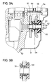
- a rectifier protection arrangement according to a second embodiment of the invention is described with reference to Figs . 3A and 3B.
- the same reference numeral as used above represents the same or substantially the same part or portion as the above-described embodiment.
- a copper-made positive fin 55 is disposed on the side of a cover 51 and a negative fin 57 is disposed on the side of a frame 50, which maintains the same effect as the first embodiment.
- Reference numeral 56 is an insulation bush
- reference numeral 58 is a iron bush.
- the iron bush 58 has a cylindrical portion and a flange that is disposed between the bush 58 and the positive fin 55.
- the bush 58 has four projections 581 on the outer periphery of the cylindrical portion.
- An output terminal device 8 is comprised of a resinous insulation bush 81 fitted to a fixing hole of the cover 11, an iron bush 82 fitted to a through hole of the insulation bush 81 and a copper-made output terminal bolt 84 fitted to the through holes of the bushes 82 and 81.
- the output terminal bolt 84 is fastened to the cover 11 by a copper nut 83, and a copper clamp member 86 that clamps a cable 85 at an end is fastened to the output terminal bolt 84 by a nut 87.
- the iron bush 82 is made of the same material as the iron bush 19, it achieves the same effect as the iron bush 19 as described above.
- a sacrificing metal (i.e. iron) bush which has a higher ionization tendency than the positive conductor member (i.e. a copper-made cooling fin), is disposed between the surface of the insulation member and the positive conductor member to maintain continuous insulation.
- the positive conductor member i.e. a copper-made cooling fin
Landscapes
- Engineering & Computer Science (AREA)
- Power Engineering (AREA)
- Microelectronics & Electronic Packaging (AREA)
- Synchronous Machinery (AREA)
Abstract
Description
Claims (6)
- A vehicle rotary electric machine having a rectifier protection arrangement, said arrangement including a positive conductor member (17) that has a higher normal electrode potential than hydrogen, a ground potential conductor member (17) and an insulation member (16) for insulating said positive conductor member, characterized in thata sacrificing metal member (19) that has a lower normal electrode potential than said positive potential conductor member is disposed between said positive conductor member and said insulation member, andsaid sacrificing metal member has a higher electric resistance than said positive potential conductor member if oxidized.
- The rotary electric machine according to claim 1, characterized in that
said sacrificing metal member are soluble as metal ions in said conductive liquid even after an oxidized layer is formed on said sacrificing metal member if the surface of said oxidized layer is covered with conductive liquid. - The rotary electric machine according to claim 1, characterized in that
said sacrificing metal member covers portions other than electric connection surface of said positive conductor member. - The rotary electric machine according to claim 1, characterized in thatsaid positive conductor member comprises a positive cooling fin (15) including positive rectifier elements (9) mounted thereon,said ground potential conductor member comprises a negative cooling fin (17) including negative rectifiers mounted thereon,said insulation member comprises a spacer (16) having a hole that maintains a space between said two fins, andsaid sacrificing metal member comprises a flanged member disposed between said spacer and one of said fins, thereby forming a rectifier of said vehicle AC generator to be fastened to a frame (4) of said vehicle AC generator by a fastening member (12, 18) piercing said spacer.
- The rotary electric machine according to claim 1, characterized in thatsaid positive conductor member comprises an output terminal bolt (84, Fig. 4) protruding from a cover (11) of said rectifier unit fixed thereto,said ground potential conductor member comprises a cover (11) or a frame (4) of said vehicle AC generator to which said cover is fixed,said insulation member comprises a resinous spacer (81) having a hole through which said output terminal bolt extends,said spacer is fixed to said cover,said sacrificing metal member (82) has a flange disposed between said spacer and said output terminal bolt, andsaid sacrificing metal member and said insulation member are fastened to each other when a cable (85) is fastened to said output terminal bolt.
- The rotary electric machine as claimed in claim 1, wherein said sacrificing metal member has a projection (581) at a portion in contact with said positive conductor member.
Applications Claiming Priority (2)
| Application Number | Priority Date | Filing Date | Title |
|---|---|---|---|
| JP2000241152 | 2000-08-09 | ||
| JP2000241152 | 2000-08-09 |
Publications (3)
| Publication Number | Publication Date |
|---|---|
| EP1180845A2 true EP1180845A2 (en) | 2002-02-20 |
| EP1180845A3 EP1180845A3 (en) | 2003-01-15 |
| EP1180845B1 EP1180845B1 (en) | 2006-10-11 |
Family
ID=18732383
Family Applications (1)
| Application Number | Title | Priority Date | Filing Date |
|---|---|---|---|
| EP01117875A Expired - Lifetime EP1180845B1 (en) | 2000-08-09 | 2001-07-23 | Vehicle rotary electric machine |
Country Status (3)
| Country | Link |
|---|---|
| US (1) | US6664675B2 (en) |
| EP (1) | EP1180845B1 (en) |
| DE (1) | DE60123715T2 (en) |
Cited By (3)
| Publication number | Priority date | Publication date | Assignee | Title |
|---|---|---|---|---|
| EP1551093A1 (en) | 2003-12-30 | 2005-07-06 | Robert Bosch Gmbh | Rectifier and alternating current generator |
| FR3017501A1 (en) * | 2014-02-07 | 2015-08-14 | Mitsubishi Electric Corp | ROTARY ELECTRIC MACHINE WITH INTEGRATED CONTROL ORDER |
| FR3119053A1 (en) * | 2021-01-20 | 2022-07-22 | Societe Nivolaisienne D'electrotechnique | EARTHING DEVICE FOR AN ELECTRIC ROTATING MACHINE |
Families Citing this family (17)
| Publication number | Priority date | Publication date | Assignee | Title |
|---|---|---|---|---|
| JP3944357B2 (en) * | 2001-02-08 | 2007-07-11 | 三菱電機株式会社 | AC generator for vehicles |
| JP2003319628A (en) * | 2002-04-19 | 2003-11-07 | Hitachi Ltd | Ac generator for vehicle |
| JP4282599B2 (en) * | 2002-10-28 | 2009-06-24 | 三菱電機株式会社 | Rectifying device for vehicle alternator and method for manufacturing the same |
| JP2004153891A (en) * | 2002-10-29 | 2004-05-27 | Mitsubishi Electric Corp | Rotating electric machine |
| US20040256925A1 (en) * | 2003-06-18 | 2004-12-23 | Transpo Electronics, Inc. | Rectifier for a vehicle alternator |
| US7291950B2 (en) * | 2004-01-14 | 2007-11-06 | Mitsubishi Denki Kabushiki Kaisha | Electric rotating machine for vehicle |
| DE102004040595A1 (en) * | 2004-08-21 | 2006-02-23 | Robert Bosch Gmbh | Rectifier device and electrical machine with such a device |
| KR100574331B1 (en) * | 2004-08-31 | 2006-04-27 | 발레오전장시스템스코리아 주식회사 | Alternator with insulation member for stator lead wire |
| JP2007330018A (en) * | 2006-06-07 | 2007-12-20 | Denso Corp | Tandem AC generator rotor |
| JP4497224B2 (en) * | 2008-04-07 | 2010-07-07 | 株式会社デンソー | Vehicle alternator |
| US7791231B2 (en) * | 2008-04-15 | 2010-09-07 | Unipoint Electric Mfg Co., Ltd. | Alternator stator assembly structure |
| CN101960694B (en) * | 2008-06-16 | 2013-05-01 | 三菱电机株式会社 | Rectifier for automotive alternator |
| JP2010013979A (en) * | 2008-07-02 | 2010-01-21 | Sanden Corp | Electric compressor |
| US8063522B2 (en) * | 2009-09-14 | 2011-11-22 | Hamilton Sundstrand Corporation | Generator rotor ground bushing |
| DE102011101932A1 (en) * | 2010-11-25 | 2012-05-31 | Baumüller Nürnberg GmbH | Electric machine |
| US8723380B2 (en) * | 2012-01-03 | 2014-05-13 | Remy Technologies, L.L.C. | Starter motor including a conductor mounting element |
| JP2019083642A (en) * | 2017-10-31 | 2019-05-30 | 株式会社デンソー | Electric rotating machine for vehicles |
Family Cites Families (12)
| Publication number | Priority date | Publication date | Assignee | Title |
|---|---|---|---|---|
| US4093529A (en) * | 1975-01-20 | 1978-06-06 | Rheem Manufacturing Company | Resistor anode for metal tank |
| JPH027Y2 (en) | 1985-01-11 | 1990-01-05 | ||
| DE3522835A1 (en) * | 1985-06-26 | 1987-01-02 | Swf Auto Electric Gmbh | AGGREGATE FOR CONVEYING FUEL |
| JPH0332340A (en) * | 1989-06-28 | 1991-02-12 | Matsushita Electric Ind Co Ltd | Intank motor |
| JPH0321973U (en) * | 1989-07-12 | 1991-03-06 | ||
| JPH06133509A (en) | 1992-10-19 | 1994-05-13 | Nippondenso Co Ltd | Rotating electric machine incorporating commutator |
| JP3514319B2 (en) * | 1993-07-26 | 2004-03-31 | 株式会社デンソー | Rotating electric machine |
| JP3543881B2 (en) * | 1995-11-08 | 2004-07-21 | 株式会社デンソー | Alternator |
| JP3820712B2 (en) * | 1997-11-27 | 2006-09-13 | 株式会社デンソー | AC generator for vehicles |
| JP3379457B2 (en) * | 1998-12-25 | 2003-02-24 | 株式会社デンソー | AC generator for vehicles |
| JP3781276B2 (en) * | 2000-08-09 | 2006-05-31 | 株式会社デンソー | Rotating electric machine for vehicles |
| JP4292702B2 (en) * | 2000-10-19 | 2009-07-08 | 株式会社デンソー | AC generator |
-
2001
- 2001-07-23 DE DE60123715T patent/DE60123715T2/en not_active Expired - Lifetime
- 2001-07-23 EP EP01117875A patent/EP1180845B1/en not_active Expired - Lifetime
- 2001-08-09 US US09/924,595 patent/US6664675B2/en not_active Expired - Fee Related
Cited By (3)
| Publication number | Priority date | Publication date | Assignee | Title |
|---|---|---|---|---|
| EP1551093A1 (en) | 2003-12-30 | 2005-07-06 | Robert Bosch Gmbh | Rectifier and alternating current generator |
| FR3017501A1 (en) * | 2014-02-07 | 2015-08-14 | Mitsubishi Electric Corp | ROTARY ELECTRIC MACHINE WITH INTEGRATED CONTROL ORDER |
| FR3119053A1 (en) * | 2021-01-20 | 2022-07-22 | Societe Nivolaisienne D'electrotechnique | EARTHING DEVICE FOR AN ELECTRIC ROTATING MACHINE |
Also Published As
| Publication number | Publication date |
|---|---|
| US6664675B2 (en) | 2003-12-16 |
| EP1180845B1 (en) | 2006-10-11 |
| US20020047360A1 (en) | 2002-04-25 |
| DE60123715D1 (en) | 2006-11-23 |
| DE60123715T2 (en) | 2007-08-23 |
| EP1180845A3 (en) | 2003-01-15 |
Similar Documents
| Publication | Publication Date | Title |
|---|---|---|
| EP1180845B1 (en) | Vehicle rotary electric machine | |
| US6657336B2 (en) | Modified output terminal structure of AC generator | |
| JP4593372B2 (en) | Rotating electric machine | |
| JP2000253625A (en) | AC generator for vehicles | |
| JP3974560B2 (en) | Rotating electric machine | |
| CN109904988B (en) | Method of making an electronic package for an electric motor | |
| JP3815059B2 (en) | AC generator for vehicles | |
| JP3180952B2 (en) | Capacitor device for automotive alternator | |
| JP2004254398A (en) | Mold motor | |
| EP0822642B1 (en) | A rectifier for an alternator, particularly for motor vehicles | |
| US6555937B2 (en) | Vehicle alternator rectifier having L-shaped connection terminals | |
| CN101938193B (en) | Rotary motor | |
| JP2002136076A (en) | Alternator | |
| JP4282599B2 (en) | Rectifying device for vehicle alternator and method for manufacturing the same | |
| US9502947B2 (en) | Generator for vehicle | |
| JP3781276B2 (en) | Rotating electric machine for vehicles | |
| EP0762614A2 (en) | AC generator | |
| US20030141042A1 (en) | High thermal capability positive heat sink for rectifier assembly | |
| JP4475215B2 (en) | Vehicle alternator | |
| JP5619301B2 (en) | Rotating electric machine for vehicles | |
| JPS6139837A (en) | Inductor type ac generator | |
| JP2001037142A (en) | AC generator for vehicles | |
| JP2012235553A (en) | Vehicle ac generator | |
| EP3014748A2 (en) | Heat sink plate, current-rectifying arrangement, and associated multiphase rotary machine | |
| JP2009112149A (en) | AC generator for vehicles |
Legal Events
| Date | Code | Title | Description |
|---|---|---|---|
| PUAI | Public reference made under article 153(3) epc to a published international application that has entered the european phase |
Free format text: ORIGINAL CODE: 0009012 |
|
| AK | Designated contracting states |
Kind code of ref document: A2 Designated state(s): AT BE CH CY DE DK ES FI FR GB GR IE IT LI LU MC NL PT SE TR |
|
| AX | Request for extension of the european patent |
Free format text: AL;LT;LV;MK;RO;SI |
|
| PUAL | Search report despatched |
Free format text: ORIGINAL CODE: 0009013 |
|
| AK | Designated contracting states |
Kind code of ref document: A3 Designated state(s): AT BE CH CY DE DK ES FI FR GB GR IE IT LI LU MC NL PT SE TR |
|
| AX | Request for extension of the european patent |
Free format text: AL;LT;LV;MK;RO;SI |
|
| RIC1 | Information provided on ipc code assigned before grant |
Free format text: 7H 02K 11/04 A, 7H 02K 11/00 B, 7H 02K 5/22 B, 7C 23F 13/00 B |
|
| 17P | Request for examination filed |
Effective date: 20030714 |
|
| AKX | Designation fees paid |
Designated state(s): DE FR GB IT |
|
| 17Q | First examination report despatched |
Effective date: 20040809 |
|
| GRAP | Despatch of communication of intention to grant a patent |
Free format text: ORIGINAL CODE: EPIDOSNIGR1 |
|
| GRAS | Grant fee paid |
Free format text: ORIGINAL CODE: EPIDOSNIGR3 |
|
| GRAA | (expected) grant |
Free format text: ORIGINAL CODE: 0009210 |
|
| AK | Designated contracting states |
Kind code of ref document: B1 Designated state(s): DE FR GB IT |
|
| REG | Reference to a national code |
Ref country code: GB Ref legal event code: FG4D |
|
| REF | Corresponds to: |
Ref document number: 60123715 Country of ref document: DE Date of ref document: 20061123 Kind code of ref document: P |
|
| ET | Fr: translation filed | ||
| REG | Reference to a national code |
Ref country code: GB Ref legal event code: 746 Effective date: 20070724 |
|
| PLBE | No opposition filed within time limit |
Free format text: ORIGINAL CODE: 0009261 |
|
| STAA | Information on the status of an ep patent application or granted ep patent |
Free format text: STATUS: NO OPPOSITION FILED WITHIN TIME LIMIT |
|
| 26N | No opposition filed |
Effective date: 20070712 |
|
| PG25 | Lapsed in a contracting state [announced via postgrant information from national office to epo] |
Ref country code: IT Free format text: LAPSE BECAUSE OF NON-PAYMENT OF DUE FEES Effective date: 20100723 |
|
| PGFP | Annual fee paid to national office [announced via postgrant information from national office to epo] |
Ref country code: DE Payment date: 20130722 Year of fee payment: 13 |
|
| PGFP | Annual fee paid to national office [announced via postgrant information from national office to epo] |
Ref country code: GB Payment date: 20130719 Year of fee payment: 13 Ref country code: FR Payment date: 20130722 Year of fee payment: 13 |
|
| PGRI | Patent reinstated in contracting state [announced from national office to epo] |
Ref country code: IT Effective date: 20141021 |
|
| PGFP | Annual fee paid to national office [announced via postgrant information from national office to epo] |
Ref country code: IT Payment date: 20130730 Year of fee payment: 13 |
|
| REG | Reference to a national code |
Ref country code: DE Ref legal event code: R119 Ref document number: 60123715 Country of ref document: DE |
|
| GBPC | Gb: european patent ceased through non-payment of renewal fee |
Effective date: 20140723 |
|
| REG | Reference to a national code |
Ref country code: FR Ref legal event code: ST Effective date: 20150331 |
|
| PG25 | Lapsed in a contracting state [announced via postgrant information from national office to epo] |
Ref country code: DE Free format text: LAPSE BECAUSE OF NON-PAYMENT OF DUE FEES Effective date: 20150203 |
|
| PGRI | Patent reinstated in contracting state [announced from national office to epo] |
Ref country code: IT Effective date: 20141021 |
|
| REG | Reference to a national code |
Ref country code: DE Ref legal event code: R119 Ref document number: 60123715 Country of ref document: DE Effective date: 20150203 |
|
| PG25 | Lapsed in a contracting state [announced via postgrant information from national office to epo] |
Ref country code: GB Free format text: LAPSE BECAUSE OF NON-PAYMENT OF DUE FEES Effective date: 20140723 Ref country code: FR Free format text: LAPSE BECAUSE OF NON-PAYMENT OF DUE FEES Effective date: 20140731 |