EP1180840A2 - Power supply negative phase detecting circuit - Google Patents
Power supply negative phase detecting circuit Download PDFInfo
- Publication number
- EP1180840A2 EP1180840A2 EP01118266A EP01118266A EP1180840A2 EP 1180840 A2 EP1180840 A2 EP 1180840A2 EP 01118266 A EP01118266 A EP 01118266A EP 01118266 A EP01118266 A EP 01118266A EP 1180840 A2 EP1180840 A2 EP 1180840A2
- Authority
- EP
- European Patent Office
- Prior art keywords
- phase
- pulse
- power supply
- electronic equipment
- negative
- Prior art date
- Legal status (The legal status is an assumption and is not a legal conclusion. Google has not performed a legal analysis and makes no representation as to the accuracy of the status listed.)
- Granted
Links
- 239000003990 capacitor Substances 0.000 claims description 11
- 238000009499 grossing Methods 0.000 claims description 6
- 230000006698 induction Effects 0.000 description 10
- 229910001219 R-phase Inorganic materials 0.000 description 9
- 230000018199 S phase Effects 0.000 description 9
- 238000010586 diagram Methods 0.000 description 8
- 238000001514 detection method Methods 0.000 description 5
- 238000010276 construction Methods 0.000 description 3
- 230000007935 neutral effect Effects 0.000 description 3
- 238000001816 cooling Methods 0.000 description 2
- 230000002159 abnormal effect Effects 0.000 description 1
- 230000003111 delayed effect Effects 0.000 description 1
- 238000012986 modification Methods 0.000 description 1
- 230000004048 modification Effects 0.000 description 1
- 230000001360 synchronised effect Effects 0.000 description 1
Images


Classifications
-
- H—ELECTRICITY
- H02—GENERATION; CONVERSION OR DISTRIBUTION OF ELECTRIC POWER
- H02H—EMERGENCY PROTECTIVE CIRCUIT ARRANGEMENTS
- H02H7/00—Emergency protective circuit arrangements specially adapted for specific types of electric machines or apparatus or for sectionalised protection of cable or line systems, and effecting automatic switching in the event of an undesired change from normal working conditions
- H02H7/08—Emergency protective circuit arrangements specially adapted for specific types of electric machines or apparatus or for sectionalised protection of cable or line systems, and effecting automatic switching in the event of an undesired change from normal working conditions for dynamo-electric motors
- H02H7/097—Emergency protective circuit arrangements specially adapted for specific types of electric machines or apparatus or for sectionalised protection of cable or line systems, and effecting automatic switching in the event of an undesired change from normal working conditions for dynamo-electric motors against wrong direction of rotation
-
- H—ELECTRICITY
- H02—GENERATION; CONVERSION OR DISTRIBUTION OF ELECTRIC POWER
- H02H—EMERGENCY PROTECTIVE CIRCUIT ARRANGEMENTS
- H02H11/00—Emergency protective circuit arrangements for preventing the switching-on in case an undesired electric working condition might result
- H02H11/004—Emergency protective circuit arrangements for preventing the switching-on in case an undesired electric working condition might result in case of incorrect phase sequence; with switching for obtaining correct phase sequence
Definitions
- the switching unit comprises a first transistor having an emitter to which the first pulse is input, a second transistor having a base to which the third pulse is input, the base of said first transistor being connected to the collector of the second transistor to perform the OR operation between the first and third pulses, a smoothing capacitor which is charged in accordance with the OR operation result, a third transistor that is connected to the smoothing capacitor and turned on/off in accordance with the charging of said smoothing capacitor, and a relay switch for switching on/off the power supply to said electronic equipment in accordance with the ON/OFF operation of the third transistor.
- the power supply negative phase detecting circuit does not need any microcomputer, and it can be implemented by a simple circuit. Therefore, it is more suitably applied to a low-cost type apparatus such as an only-cooling type air conditioner or the like to which low cost is required.
Landscapes
- Emergency Protection Circuit Devices (AREA)
- Control Of Voltage And Current In General (AREA)
Abstract
Description
- The present invention relates to a negative phase detecting circuit for a three-phase three-wire or three-phase four-wire type power supply source used as a power supply source for electronic equipment using a three-phase induction motor such as an air conditioner or the like.
- In a case where three-phase AC power is supplied to electronic equipment (for example, an air conditioner) using a three-phase induction motor (for example, a compressor of an air conditioner or the like), if the wiring between the three-phase AC power supply source and the electronic equipment is erroneous, there would occur such a disadvantage that the three-phase induction motor is rotated in the opposite direction to the expected direction or the like. Therefore, there has been proposed a negative phase detecting circuit for power supply for judging whether the wiring between a three-phase AC power supply source and electronic equipment is correct or not, and also whether the three-phase AC power supply source itself is proper or not (disclosed in Japanese Laid-open Patent Application No. Hei-8-289466).
- Fig. 1 is a circuit diagram showing the construction of the power supply negative phase detecting circuit as described above.
- According to the power supply negative phase detecting circuit shown in Fig. 1, two kinds of pulses, that is, a first pulse A (R-S) and a second pulse B (S-T) are generated from AC voltages of R-phase, S-phase and T-phase, and the phase difference between the first and second pulses is read out by a microcomputer to judge whether the phase is positive (correct wiring) or negative (erroneous wiring).
- Further, there is known a low-cost outdoor unit of an only-cooling type air conditioner which is not equipped with any outdoor control board for controlling an outdoor unit. In this type low-cost outdoor unit, the control of the outdoor unit is carried out by the indoor side, and also a negative-phase preventing relay is provided to detect the negative phase and protect the outdoor unit under the negative-phase state.
- However, since the internal parts of the negative-phase preventing relay are broken due to high voltage noises (thunder surge or the like) and thus a protecting device such as an arrester or the like must be separately equipped.
- An object of the present invention is to perform negative phase detection by adding a simple electrical circuit to low-cost equipment and protect the electrical circuit from high voltage noises without mounting a varistor, an arrester or the like on a board, whereby the negative-phase detection, the protecting operation and the other functional performance can be supplied in a lower cost than when a negative-phase preventing relay is used.
- In order to attain the above object, according to a first aspect of the present invention, there is provided a power supply negative-phase detecting circuit for electronic equipment using a three-phase AC power supply source, characterized by comprising: a pulse generator for generating a first pulse indicating the phase difference between any pair of two phases of three-phase AC power to be supplied to the electronic equipment, and a second pulse indicating the phase difference between another pair of two phases of the three-phase AC power; a differentiating circuit for generating a third pulse from the second pulse in synchronism with the rise-up of the second pulse so that the third pulse has a pulse width smaller than the phase difference between the first and second pulses; and a switching unit for subjecting the first pulse and the third pulse to OR operation and turning on/off the power supply to the electronic equipment on the basis of the OR operation result of the first and third pulses.
- According to a second aspect of the present invention, in the power supply negative-phase detecting circuit of the first aspect of the present invention, when the three-phase AC power to be supplied to the electronic equipment has negative phase, the switching unit turns off the power supply to the electronic equipment.
- According to a third aspect of the present invention, in the power supply negative-phase detecting circuit of the first aspect of the present invention, the differentiating circuit comprises a capacitor and a resistor.
- According to a fourth aspect of the present invention, in the power supply negative-phase detecting circuit of the third aspect of the present invention, the switching unit comprises a first transistor having an emitter to which the first pulse is input, a second transistor having a base to which the third pulse is input, the base of said first transistor being connected to the collector of the second transistor to perform the OR operation between the first and third pulses, a smoothing capacitor which is charged in accordance with the OR operation result, a third transistor that is connected to the smoothing capacitor and turned on/off in accordance with the charging of said smoothing capacitor, and a relay switch for switching on/off the power supply to said electronic equipment in accordance with the ON/OFF operation of the third transistor.
- According to a fifth aspect of the present invention, in the power supply negative-phase detecting circuit of the first aspect of the present invention, there is further provided alarm means for emitting an alarm when the three-phase AC power to be supplied to the electronic equipment has negative phase.
- According to a sixth aspect of the present invention, in the power supply negative-phase detecting circuit of the fifth aspect of the present invention, when the three-phase AC power to be supplied to the electronic equipment has negative phase, the switching unit turns off the power supply to the electronic equipment, and simultaneously the alarm means emits the alarm.
-
- Fig. 1 is an electrical circuit diagram showing a conventional three-phase three-wire type power supply negative phase detecting circuit;
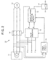
- Fig. 2 is a block diagram showing an embodiment of a power supply negative phase detecting circuit according to the present invention;
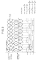
- Fig. 3 is a diagram showing the waveforms of three-phase AC voltages of 50Hz supplied from a three-phase AC power source;
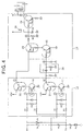
- Fig. 4 is a electrical circuit diagram showing the construction of a pulse generator and a negative phase detecting circuit shown in Fig. 2;
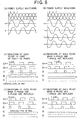
- Fig. 5 is a waveform diagram showing a first pulse A and a second pulse B generated in the pulse generator shown in Fig. 2; and
- Fig. 6 is time charts showing the voltage waveforms of R-phase, S-phase and T-phase, the differential voltage waveforms thereof, and the voltage waveforms (pulses) generated at respective points the electrical circuit shown in Fig. 4.
-
- A preferred embodiment according to the present invention will be described with reference to the accompanying drawings.
- Fig. 2 is a block diagram showing an embodiment of a power supply negative phase detecting circuit according to the present invention.
- The power supply negative
phase detecting circuit 10 shown in Fig. 2 is used when three-phase AC power is supplied from a three-phase four-wire type three-phase ACpower supply source 11 to aninduction motor 12 as electronic equipment to actuate theinduction motor 12. The power supply negativephase detecting circuit 10 comprises apulse generator 13, a negativephase detecting circuit 14, apower supply circuit 15, apower supply switch 16 and aremote controller 17. - The three-phase AC
power supply source 11 generates three-phase AC power of R-phase, S-phase and T-phase as shown in Fig. 3. Fig. 3 shows the waveforms of the three-phase AC voltages having the power supply frequency of 50Hz. In Fig. 3, N-phase represents a neutral phase. The N-phase is generally grounded, and thus the N-phase is handled as 0V (volt) in Fig. 3. - Specifically, the upper stage of Fig. 3 represents the voltage waveforms of the respective phases (R-phase, S-phase, T-phase), the middle stage of Fig. 3 represents the waveforms of the inter-line voltages of the respective phases (i.e., R-S, S-T, T-R), and the lower stage of Fig. 3 represents the waveforms of pulses generated on the basis of the inter-line voltages of (R-S), (S-T) and (T-R).
- Fig. 4 is an electrical circuit diagram showing the construction of the
pulse generator 13 and the negativephase detecting circuit 14 of the power supply negative phase generating circuit shown in Fig. 2, and Fig. 6 is time charts showing the voltage waveforms (pulses) at some points (3 ○ to 7 ○) of the electrical circuit of Fig. 4 in various cases. - As shown in Fig. 4, the
pulse generating circuit 13 is mainly constructed byphotocouplers transistors AC power source 11. That is, thephotocoupler 18 and thetransistor 20 generates the first pulse A (see Fig. 5) from the AC voltages of R-phase and S-phase, and thephotocoupler 19 and thetransistor 21 generates the second pulse B (see Fig. 5) from the AC voltages of S-phase and T-phase. Further, the negativephase detecting circuit 14 is mainly constructed by threetransistors - Here, the pulse width of the first pulse A and the second pulse B is equal to about 10ms (milli-second) when the frequency of the three-phase
AC power source 11 is equal to 50Hz, and also to about 8.3ms when the frequency of the three-phaseAC power source 11 is equal to 60Hz. - The
power supply circuit 15 takes any two phase AC power from the three-phase AC power supply source 11 (in this embodiment, AC power of R-phase and S-phase) to convert the two-phase AC power to DC power, and then supplies the DC power to the electrical circuit shown in Fig. 4. In this embodiment, the DC power having DC voltage of +5V (volts) is supplied from thepower supply circuit 15 to thepulse generator 13 and the negativephase detecting circuit 14. - Next, the operation of the electrical circuit (the
pulse generator 13 and the negative phase detecting circuit 14) shown in Fig. 4 will be described with reference to Figs. 4 and 6. - When the power supplied to the circuit shown in Fig. 4 has positive phase ((C) of Fig. 6), the sine-wave voltage of R-T is applied to the
primary side 1 ○ of thephotocoupler 18. Thephotocoupler 18 is turned on and thus thetransistor 20 is turned on at the portion (period) where the voltage of R-phase > the voltage of T-phase, so that a (R-T) pulse train having approximately 50% duty occurs at 3 ○. Likewise, a (S-T) pulse train occurs at 4 ○. Here, comparing both the pulse trains, the (S-T) pulse train is delayed from the (R-T) pulse train by ΔT (3.3ms for 50Hz, 2.77ms for 60Hz) theoretically. - Next, when the respective phases are replaced by one another and thus the power has negative phase ((D) to (F) of Fig. 6), the pulse at 4 ○ leads the pulse at 3 ○ by Δt in all the cases ((D) to (F)), and this is different from the positive phase case.
- Therefore, a pulse at 5 ○(pulse width d < Δt). synchronized with the rise-up of the pulse at 4 ○is generated by a differentiating
circuit 25 comprising a capacitor C1 and a resistor R3, and the pulses at 3 ○ and 5 ○are subjected to OR operation. If the pulse at 3 ○is H (High level), a soothing capacitor C2 is charged and set to H level, and the point at 6 ○ is set to H level, so that thetransistor 24 is turned on. Here, the discharge time constant (C2 · R4//base resistance of transistor) must be set to a sufficiently long value as compared with the period of the power supply frequency. - Further, when the power supply source is negative phase, even if the pulses at 3 ○ and 5 ○are subjected to OR operation, the capacitor C2 is not charged and the point at 6 ○ is kept under L state, so that the
transistor 24 is kept to an OFF state. On the other hand, when the power supply source is positive phase, thetransistor 24 is turned ON, and the switch RY is also turned on. Therefore, a power supply source serving as a load can be turned on/off or an alarm display can be made by connecting the primary side of the contact point of the switch RY to the power supply source and connecting the secondary side of the contact point of the switch RY to the load (three-phase induction motor or the like), that is, the electric circuit shown in Fig. 4 can be used to meet various applied targets - Further, when the negative phase detecting circuit is used for a single phase power supply source, the negative phase detection is not needed, and thus the circuit is designed so that the switch RY is kept to be forcedly turned on by turning on a
switch 26 from the remote controller or the like. - When the power supply source is three-phase four-wire type (mainly, overseas), a neutral point N (neutral) phase is added to the three-phase three-wire, and thus the number of patterns of the negative phase is increased. When the N-phase and another phase are replaced by each other, the inter-line voltage is equal to 1/{2. Therefore, by selecting the constants of the input resistors R1 and R2, the photocoupler can be prevented from being turned on even when the N-phase is contaminated, and thus the negative-phase detection can be also performed in the case of the three-phase four-wire system.
- The order of the power source R-S-T is S-T-R, T-R-S, it is impossible to perform the negative-phase detection. However, if the order of the three phases is merely displaced, three-phase equipment practically suffers no damage, and thus there is no special problem.
- According to the above-described embodiment, the negative
phase detecting circuit 14 judges whether the wiring between the three-phase AC power source 11 (three-phase three-wire type or three-phase four-wire type) and theinduction motor 12 is proper or not at the stage that thecircuit 14 is started and then periodically generates the first pulse A and the second pulse B on the basis of the voltages (R, S, T) from the three-phaseAC power source 11. Therefore, it can be accurately judged whether the three-phaseAC power source 11 is proper or not and whether the wiring between the three-phase. AC power source and theinduction motor 12 is proper or not. - The present invention is not limited to the above-described embodiment, and various modifications may be made. For example, in. the above embodiment, the electronic equipment is assumed to be an
induction motor 12. However, the present invention may be applied to other electronic equipment using a three-phase AC power source. - Further, in the above embodiment, when the three-phase
AC power source 11 is abnormal or when the wiring between the three-phaseAC power source 11 and theinduction motor 12 is erroneous, a display indicating this fact may be displayed on adisplay portion 23 of theremote controller 17, or an alarm sound may be generated. - Still further, the above embodiment is applied to the three-phase four-wire type wiring of R-phase, S-phase, T-phase, N-phase, however, the present invention may be applied to three-phase three-wire type wiring.
- As described above, according to the present invention, the power supply negative phase detecting circuit does not need any microcomputer, and it can be implemented by a simple circuit. Therefore, it is more suitably applied to a low-cost type apparatus such as an only-cooling type air conditioner or the like to which low cost is required.
- Further, according to the present invention, when negative-phase power is applied to electronic equipment, the power supply negative phase detecting circuit can pick up an alarm signal to make an alarm display. In addition, countermeasures to noise and surge can be taken.
Claims (6)
- A power supply negative-phase detecting circuit for electronic equipment using a three-phase AC power supply source, characterized by comprising:a pulse generator for generating a first pulse indicating the phase difference between any pair of two phases of three-phase AC power to be supplied to said electronic equipment, and a second pulse indicating the phase difference between another pair of two phases of the three-phase AC power;a differentiating circuit for generating a third pulse from the second pulse in synchronism with the rise-up of the second pulse so that the third pulse has a pulse width smaller than the phase difference between the first and second pulses; anda switching unit for subjecting the first pulse and the third pulse to OR operation and turning on/off the power supply to said electronic equipment on the basis of the OR operation result of the first and third pulses.
- The power supply negative-phase detecting circuit as claimed in claim 1, wherein when the three-phase AC power to be supplied to said electronic equipment has negative phase, said switching unit turns off the power supply to said electronic equipment.
- The power supply negative-phase detecting circuit as claimed in claim 1, wherein said differentiating circuit comprises a capacitor and a resistor.
- The power supply negative-phase detecting circuit as claimed in claim 3, wherein said switching unit comprises a first transistor having an emitter to which the first pulse is input, a second transistor having a base to which the third pulse is input, the base of said first transistor being connected to the collector of said second transistor to perform the OR operation between the first and third pulses, a smoothing capacitor which is charged in accordance with the OR operation result, a third transistor that is connected to said smoothing capacitor and turned on/off in accordance with the charging of said smoothing capacitor, and a relay switch for switching on/off the power supply to said electronic equipment in accordance with the ON/OFF operation of said third transistor.
- The power supply negative-phase detecting circuit as claimed in claim 1, further including alarm means for emitting an alarm when the three-phase AC power to be supplied to said electronic equipment has negative phase.
- The power supply negative-phase detecting circuit as claimed in claim 5, wherein when the three-phase AC power to be supplied to said electronic equipment has negative phase, said switching unit turns off the power supply to said electronic equipment, and simultaneously said alarm means emits the alarm.
Applications Claiming Priority (2)
| Application Number | Priority Date | Filing Date | Title |
|---|---|---|---|
| JP2000242621A JP4107789B2 (en) | 2000-08-10 | 2000-08-10 | Power supply reverse phase detection circuit |
| JP2000242621 | 2000-08-10 |
Publications (3)
| Publication Number | Publication Date |
|---|---|
| EP1180840A2 true EP1180840A2 (en) | 2002-02-20 |
| EP1180840A3 EP1180840A3 (en) | 2005-06-08 |
| EP1180840B1 EP1180840B1 (en) | 2014-09-03 |
Family
ID=18733621
Family Applications (1)
| Application Number | Title | Priority Date | Filing Date |
|---|---|---|---|
| EP01118266.4A Expired - Lifetime EP1180840B1 (en) | 2000-08-10 | 2001-07-30 | Power supply negative phase detecting circuit |
Country Status (3)
| Country | Link |
|---|---|
| US (1) | US6614217B2 (en) |
| EP (1) | EP1180840B1 (en) |
| JP (1) | JP4107789B2 (en) |
Cited By (4)
| Publication number | Priority date | Publication date | Assignee | Title |
|---|---|---|---|---|
| US6614217B2 (en) * | 2000-08-10 | 2003-09-02 | Sanyo Electronic Co., Ltd. | Power supply negative phase detecting circuit |
| EP1411612A3 (en) * | 2002-10-17 | 2006-09-27 | Lg Electronics Inc. | Apparatus and method for detecting phase state |
| WO2014056505A1 (en) * | 2012-10-08 | 2014-04-17 | Lodam Electronics A/S | Phase sequence detection |
| CN108131317A (en) * | 2017-12-04 | 2018-06-08 | 深圳创维空调科技有限公司 | A kind of outer wind turbine of air-conditioning and its counnter attack rotary driving device and method |
Families Citing this family (16)
| Publication number | Priority date | Publication date | Assignee | Title |
|---|---|---|---|---|
| JP4110510B2 (en) * | 2002-03-08 | 2008-07-02 | 三菱電機株式会社 | Air conditioner miswiring detector |
| US6685290B1 (en) * | 2003-01-30 | 2004-02-03 | Hewlett-Packard Development Company, L.P. | Printer consumable having data storage for static and dynamic calibration data, and methods |
| KR100707419B1 (en) * | 2004-12-03 | 2007-04-13 | 엘지전자 주식회사 | Air conditioner power generation system capable of solving phase imbalance and its method of eliminating phase imbalance |
| WO2007094074A1 (en) * | 2006-02-17 | 2007-08-23 | Fujitsu Limited | Signal processing method, signal processing apparatus and analog/digital converting apparatus |
| JP2007259641A (en) * | 2006-03-24 | 2007-10-04 | Mitsubishi Electric Corp | Abnormality detection device for frozen and refrigerated showcase |
| RU2306651C1 (en) * | 2006-03-28 | 2007-09-20 | Открытое акционерное общество Арзамасское научно-производственное предприятие "ТЕМП-АВИА" (ОАО АНПП "ТЕМП-АВИА") | Induction-motor checkup system |
| CN101354407B (en) * | 2007-07-23 | 2012-05-30 | 鸿富锦精密工业(深圳)有限公司 | Power supply apparatus |
| US9000787B2 (en) * | 2007-12-21 | 2015-04-07 | Carrier Corporation | Method and system for low-power three-phase detection |
| US8988026B2 (en) * | 2012-07-31 | 2015-03-24 | Rockwell Automation Technologies, Inc. | Single phase operation of a three-phase drive system |
| US9562935B2 (en) * | 2012-10-19 | 2017-02-07 | Lear Corporation | Apparatus and method for detecting a phase sequence in a vehicle |
| CN104037749B (en) * | 2013-03-04 | 2017-04-12 | 大族激光科技产业集团股份有限公司 | AC power supply control system |
| CN104777436A (en) * | 2015-03-19 | 2015-07-15 | 东菱技术有限公司 | Novel alternating current power supply monitoring device |
| JP6461874B2 (en) * | 2015-09-14 | 2019-01-30 | ダイキン工業株式会社 | Judgment method of connection order, judgment method of phase loss |
| US20170205449A1 (en) * | 2016-01-20 | 2017-07-20 | Test Research, Inc. | Test device and alternating current power detection method of the same |
| US10139454B2 (en) * | 2016-01-20 | 2018-11-27 | Test Research, Inc. | Test device and alternating current power detection method of the same |
| CN107482585B (en) * | 2017-10-02 | 2020-05-15 | 南通雄亚机电制造有限公司 | Pulse drive-based cold end overcurrent protection type drive circuit and motor drive circuit |
Citations (2)
| Publication number | Priority date | Publication date | Assignee | Title |
|---|---|---|---|---|
| US4199798A (en) | 1978-03-13 | 1980-04-22 | Eaton Corporation | Phase balance monitoring system incorporating voltage and phase sequence monitoring |
| US5057963A (en) | 1989-03-30 | 1991-10-15 | Kabushiki Kaisha Toshiba | Opposite phase detecting device for alternating current electrical equipment |
Family Cites Families (11)
| Publication number | Priority date | Publication date | Assignee | Title |
|---|---|---|---|---|
| JPS52112355A (en) * | 1976-03-18 | 1977-09-20 | Shin Shirasuna Electric Corp | Method of detecting whether or not phase difference between two signals is constant |
| US4553018A (en) * | 1983-10-27 | 1985-11-12 | Mitsubishi Denki Kabushiki Kaisha | Short circuiting transfer arc welding machine |
| USRE33874E (en) * | 1986-05-22 | 1992-04-07 | Franklin Electric Co., Inc. | Electric motor load sensing system |
| JPH03244983A (en) * | 1990-02-23 | 1991-10-31 | Toshiba Corp | Air conditioner |
| US5184063A (en) * | 1992-02-13 | 1993-02-02 | Carrier Corporation | Three phase reversal detection system |
| EP0661453B1 (en) * | 1993-12-28 | 2003-04-23 | Sanyo Electric Co. Ltd | Air conditioner and inverter driving circuit therefor |
| JPH08289466A (en) * | 1995-04-17 | 1996-11-01 | Sanyo Electric Co Ltd | Power supply miswiring detection device |
| JPH10289466A (en) | 1997-04-10 | 1998-10-27 | Matsushita Electric Ind Co Ltd | Optical disk drive |
| JP3920440B2 (en) * | 1998-01-29 | 2007-05-30 | 三洋電機株式会社 | Compressor control system for air conditioner |
| JP2000228822A (en) * | 1999-02-05 | 2000-08-15 | Tsubakimoto Chain Co | Overload protection device and reduction gear provided with the same |
| JP4107789B2 (en) * | 2000-08-10 | 2008-06-25 | 三洋電機株式会社 | Power supply reverse phase detection circuit |
-
2000
- 2000-08-10 JP JP2000242621A patent/JP4107789B2/en not_active Expired - Fee Related
-
2001
- 2001-07-26 US US09/915,655 patent/US6614217B2/en not_active Expired - Fee Related
- 2001-07-30 EP EP01118266.4A patent/EP1180840B1/en not_active Expired - Lifetime
Patent Citations (2)
| Publication number | Priority date | Publication date | Assignee | Title |
|---|---|---|---|---|
| US4199798A (en) | 1978-03-13 | 1980-04-22 | Eaton Corporation | Phase balance monitoring system incorporating voltage and phase sequence monitoring |
| US5057963A (en) | 1989-03-30 | 1991-10-15 | Kabushiki Kaisha Toshiba | Opposite phase detecting device for alternating current electrical equipment |
Cited By (6)
| Publication number | Priority date | Publication date | Assignee | Title |
|---|---|---|---|---|
| US6614217B2 (en) * | 2000-08-10 | 2003-09-02 | Sanyo Electronic Co., Ltd. | Power supply negative phase detecting circuit |
| EP1411612A3 (en) * | 2002-10-17 | 2006-09-27 | Lg Electronics Inc. | Apparatus and method for detecting phase state |
| WO2014056505A1 (en) * | 2012-10-08 | 2014-04-17 | Lodam Electronics A/S | Phase sequence detection |
| CN104937425A (en) * | 2012-10-08 | 2015-09-23 | 洛达姆电子公司 | Phase sequence detection |
| CN108131317A (en) * | 2017-12-04 | 2018-06-08 | 深圳创维空调科技有限公司 | A kind of outer wind turbine of air-conditioning and its counnter attack rotary driving device and method |
| CN108131317B (en) * | 2017-12-04 | 2020-06-09 | 深圳创维空调科技有限公司 | Air conditioner external fan and anti-reverse driving device and method thereof |
Also Published As
| Publication number | Publication date |
|---|---|
| US6614217B2 (en) | 2003-09-02 |
| JP2002055136A (en) | 2002-02-20 |
| EP1180840A3 (en) | 2005-06-08 |
| JP4107789B2 (en) | 2008-06-25 |
| US20020027432A1 (en) | 2002-03-07 |
| EP1180840B1 (en) | 2014-09-03 |
Similar Documents
| Publication | Publication Date | Title |
|---|---|---|
| US6614217B2 (en) | Power supply negative phase detecting circuit | |
| US6777954B2 (en) | Faulty wiring detection device for air conditioner | |
| USRE39446E1 (en) | Power filter circuit responsive to supply system fault conditions | |
| US4943886A (en) | Circuitry for limiting current between power inverter output terminals and ground | |
| US20120249038A1 (en) | Ground scheme identification method | |
| US4421976A (en) | System for monitoring heater elements of electric furnaces | |
| CN102428619B (en) | Incorrect connection detecting device | |
| EP0633640B1 (en) | An earth leakage unit | |
| US6570334B2 (en) | Gas-discharge lamp including a fault protection circuit | |
| US5548207A (en) | Missing phase detector | |
| EP1294087B1 (en) | Power supply | |
| US20080024138A1 (en) | Identifying apparatus for ac power supply arrangement | |
| CN1139950C (en) | Circuit for monitoring A. C. power switch | |
| US5821790A (en) | Power line synchronization conditioner | |
| KR102164483B1 (en) | Ark detection circuit using damped oscillation | |
| JPH06503941A (en) | Phase angle control circuit | |
| US5608311A (en) | AC input for digital processor with capacitively coupled immunity and surge withstand | |
| EP0083804B1 (en) | An ac current detection circuit for a rotor driving supply source of a rotating anode x-ray tube | |
| US20220413049A1 (en) | Sensing a Switching State of an Electromechanical Switching Element | |
| EP0677910B1 (en) | Overvoltage protection | |
| JP3327613B2 (en) | Control device for vehicle charging generator | |
| JP3273814B2 (en) | Open phase detection circuit | |
| JPH0516876Y2 (en) | ||
| JP3145558B2 (en) | Signal input circuit | |
| SU1580479A1 (en) | Device for protecting three-phase induction motor from break of phases |
Legal Events
| Date | Code | Title | Description |
|---|---|---|---|
| PUAI | Public reference made under article 153(3) epc to a published international application that has entered the european phase |
Free format text: ORIGINAL CODE: 0009012 |
|
| 17P | Request for examination filed |
Effective date: 20010730 |
|
| AK | Designated contracting states |
Kind code of ref document: A2 Designated state(s): AT BE CH CY DE DK ES FI FR GB GR IE IT LI LU MC NL PT SE TR |
|
| AX | Request for extension of the european patent |
Free format text: AL;LT;LV;MK;RO;SI |
|
| PUAL | Search report despatched |
Free format text: ORIGINAL CODE: 0009013 |
|
| AK | Designated contracting states |
Kind code of ref document: A3 Designated state(s): AT BE CH CY DE DK ES FI FR GB GR IE IT LI LU MC NL PT SE TR |
|
| AX | Request for extension of the european patent |
Extension state: AL LT LV MK RO SI |
|
| AKX | Designation fees paid |
Designated state(s): DE GB |
|
| 17Q | First examination report despatched |
Effective date: 20111115 |
|
| GRAP | Despatch of communication of intention to grant a patent |
Free format text: ORIGINAL CODE: EPIDOSNIGR1 |
|
| INTG | Intention to grant announced |
Effective date: 20140304 |
|
| GRAS | Grant fee paid |
Free format text: ORIGINAL CODE: EPIDOSNIGR3 |
|
| GRAA | (expected) grant |
Free format text: ORIGINAL CODE: 0009210 |
|
| AK | Designated contracting states |
Kind code of ref document: B1 Designated state(s): DE GB |
|
| REG | Reference to a national code |
Ref country code: GB Ref legal event code: FG4D |
|
| REG | Reference to a national code |
Ref country code: DE Ref legal event code: R096 Ref document number: 60148983 Country of ref document: DE Effective date: 20141016 |
|
| REG | Reference to a national code |
Ref country code: DE Ref legal event code: R097 Ref document number: 60148983 Country of ref document: DE |
|
| PLBE | No opposition filed within time limit |
Free format text: ORIGINAL CODE: 0009261 |
|
| STAA | Information on the status of an ep patent application or granted ep patent |
Free format text: STATUS: NO OPPOSITION FILED WITHIN TIME LIMIT |
|
| 26N | No opposition filed |
Effective date: 20150604 |
|
| PGFP | Annual fee paid to national office [announced via postgrant information from national office to epo] |
Ref country code: DE Payment date: 20170725 Year of fee payment: 17 Ref country code: GB Payment date: 20170726 Year of fee payment: 17 |
|
| REG | Reference to a national code |
Ref country code: DE Ref legal event code: R119 Ref document number: 60148983 Country of ref document: DE |
|
| GBPC | Gb: european patent ceased through non-payment of renewal fee |
Effective date: 20180730 |
|
| PG25 | Lapsed in a contracting state [announced via postgrant information from national office to epo] |
Ref country code: GB Free format text: LAPSE BECAUSE OF NON-PAYMENT OF DUE FEES Effective date: 20180730 Ref country code: DE Free format text: LAPSE BECAUSE OF NON-PAYMENT OF DUE FEES Effective date: 20190201 |