EP1180702A1 - Protective device in a connector arrangement for optical fibers - Google Patents
Protective device in a connector arrangement for optical fibers Download PDFInfo
- Publication number
- EP1180702A1 EP1180702A1 EP01118676A EP01118676A EP1180702A1 EP 1180702 A1 EP1180702 A1 EP 1180702A1 EP 01118676 A EP01118676 A EP 01118676A EP 01118676 A EP01118676 A EP 01118676A EP 1180702 A1 EP1180702 A1 EP 1180702A1
- Authority
- EP
- European Patent Office
- Prior art keywords
- plug
- slide
- housing
- receiver
- mating
- Prior art date
- Legal status (The legal status is an assumption and is not a legal conclusion. Google has not performed a legal analysis and makes no representation as to the accuracy of the status listed.)
- Granted
Links
- 239000013307 optical fiber Substances 0.000 title claims abstract description 33
- 230000001681 protective effect Effects 0.000 title claims abstract description 17
- 230000013011 mating Effects 0.000 claims abstract description 38
- 230000009993 protective function Effects 0.000 claims 1
- 230000000717 retained effect Effects 0.000 claims 1
- 230000003287 optical effect Effects 0.000 description 7
- 230000005540 biological transmission Effects 0.000 description 3
- 230000007547 defect Effects 0.000 description 3
- 230000007246 mechanism Effects 0.000 description 2
- RYGMFSIKBFXOCR-UHFFFAOYSA-N Copper Chemical compound [Cu] RYGMFSIKBFXOCR-UHFFFAOYSA-N 0.000 description 1
- 239000000919 ceramic Substances 0.000 description 1
- 229910052802 copper Inorganic materials 0.000 description 1
- 239000010949 copper Substances 0.000 description 1
- 230000005670 electromagnetic radiation Effects 0.000 description 1
- 238000012423 maintenance Methods 0.000 description 1
- 239000000463 material Substances 0.000 description 1
- 239000002184 metal Substances 0.000 description 1
- 229910052751 metal Inorganic materials 0.000 description 1
- 230000035945 sensitivity Effects 0.000 description 1
Images


Classifications
-
- G—PHYSICS
- G02—OPTICS
- G02B—OPTICAL ELEMENTS, SYSTEMS OR APPARATUS
- G02B6/00—Light guides; Structural details of arrangements comprising light guides and other optical elements, e.g. couplings
- G02B6/24—Coupling light guides
- G02B6/36—Mechanical coupling means
- G02B6/38—Mechanical coupling means having fibre to fibre mating means
- G02B6/3807—Dismountable connectors, i.e. comprising plugs
- G02B6/3833—Details of mounting fibres in ferrules; Assembly methods; Manufacture
- G02B6/3847—Details of mounting fibres in ferrules; Assembly methods; Manufacture with means preventing fibre end damage, e.g. recessed fibre surfaces
- G02B6/3849—Details of mounting fibres in ferrules; Assembly methods; Manufacture with means preventing fibre end damage, e.g. recessed fibre surfaces using mechanical protective elements, e.g. caps, hoods, sealing membranes
-
- G—PHYSICS
- G02—OPTICS
- G02B—OPTICAL ELEMENTS, SYSTEMS OR APPARATUS
- G02B6/00—Light guides; Structural details of arrangements comprising light guides and other optical elements, e.g. couplings
- G02B6/24—Coupling light guides
- G02B6/36—Mechanical coupling means
- G02B6/38—Mechanical coupling means having fibre to fibre mating means
- G02B6/3807—Dismountable connectors, i.e. comprising plugs
- G02B6/381—Dismountable connectors, i.e. comprising plugs of the ferrule type, e.g. fibre ends embedded in ferrules, connecting a pair of fibres
- G02B6/3825—Dismountable connectors, i.e. comprising plugs of the ferrule type, e.g. fibre ends embedded in ferrules, connecting a pair of fibres with an intermediate part, e.g. adapter, receptacle, linking two plugs
-
- G—PHYSICS
- G02—OPTICS
- G02B—OPTICAL ELEMENTS, SYSTEMS OR APPARATUS
- G02B6/00—Light guides; Structural details of arrangements comprising light guides and other optical elements, e.g. couplings
- G02B6/24—Coupling light guides
- G02B6/36—Mechanical coupling means
- G02B6/38—Mechanical coupling means having fibre to fibre mating means
- G02B6/3807—Dismountable connectors, i.e. comprising plugs
- G02B6/389—Dismountable connectors, i.e. comprising plugs characterised by the method of fastening connecting plugs and sockets, e.g. screw- or nut-lock, snap-in, bayonet type
- G02B6/3893—Push-pull type, e.g. snap-in, push-on
-
- G—PHYSICS
- G02—OPTICS
- G02B—OPTICAL ELEMENTS, SYSTEMS OR APPARATUS
- G02B6/00—Light guides; Structural details of arrangements comprising light guides and other optical elements, e.g. couplings
- G02B6/24—Coupling light guides
- G02B6/42—Coupling light guides with opto-electronic elements
- G02B6/4292—Coupling light guides with opto-electronic elements the light guide being disconnectable from the opto-electronic element, e.g. mutually self aligning arrangements
Definitions
- the invention relates to a connector arrangement with a plug and an associated mating plug.
- connectors which couple optical fibers to one another.
- Optical fibers are often used for data transmission when large amounts of data are to be transmitted at high transmission rates or parallel transmission of data on a plurality of channels is desired.
- the connector arrangement couples an optical fiber and an optical element, for example a further optical fiber or a diode, to one another and conventionally consists of a plug and an associated mating plug.
- Optical fibers are also used, for example, in motor vehicles because of their low sensitivity to interference from electromagnetic radiation.
- During assembly, maintenance or repair where a plug is in an unmated condition there are various protective devices which may be applied to the plug to protect the optical fibers.
- a known protective device for a connector arrangement is, for example, a protective cap which is removed before connection of the plug to the mating plug. Removal of the cap involves an additional step in the assembly of the connector arrangement and also leads to storage problems with the cap.
- a further protective device is known from US 5,506,922 in the form of a protective flap which can be opened for connection to the optical fiber.
- the flap opens upon connection of the plug to the mating plug and is a complex mechanism which is susceptible to defects.
- a further common protective device is a collar arranged about the optical fiber which protects the optical fiber and upon connection to the mating plug is connected to the optical element thereof.
- the collar is, however, only suitable for connecting optical fibers to one another because in the event of connection to a different optical element, the diameter of the collar is too large to obtain a protective effect.
- a collar can only be designed for connection to an optical element of a certain size.
- An object of the present invention is to provide a simple protective device for a plug in a connector arrangement which is only infrequently susceptible to defects.
- the plug and an associated mating plug have a housing which has at least one axial receiver for an optical fiber and a protective device movably mounted in the housing for protecting the optical fiber.
- the protective device is designed as a slide which can be moved axially to the receiver and has a through aperture for the optical fiber and/or the receiver.
- the protective device can therefore be suitably displaced for a connection to the optical element of the mating plug, wherein the through aperture makes the optical fiber receiver accessible for connection.
- the slide is also designed simply so as to be only infrequently susceptible to defects.
- the movement direction of the slide preferably corresponds to a plug-in direction in which the plug and mating plug are connected to one another, as a result of which the necessary mechanisms are simplified and therefore have fewer sources of error.
- the slide in a unmated state the slide is located in a starting position in front of the front end of the receiver and in the mated state, the front end of the receiver projects through the aperture. In its starting position, the slide therefore protects the optical fiber in the receiver, but exposes it in the mated state for connection with the optical element the mating plug.
- Figures 1 to 3 show a preferred embodiment of the invention.
- a plug of a connector arrangement in Figure 1 has a housing 10 which has two receivers 11 and 12 for optical fibers.
- a movably mounted protective device to protect the optical fibers which can be inserted into the receivers 11 and 12 is designed as a slide 20 in the housing 10. The slide 20 can be moved axially with respect to the receivers 11 and 12 and has apertures 21 and 22 for the optical fibers and/or the receivers.
- the movement direction of the slide 20 corresponds to a plug-in direction in which the plug and the mating plug, not shown in this figure, are connected to one another.
- the slide 20 is arranged in its starting position in front of the front end of the receiver.
- the plug housing and the slide can be made, for example, from plastic material, ceramics or metal.
- Figure 2 shows the plug from Figure 1 with the slide 20 in a plugged-in or mated condition, wherein the slide 20 is moved with respect to the housing 10 and its receivers 11 and 12 projecting through the apertures 21 and 22.
- optical fibers or a plurality of optical fibers can be connected to a plug utilising this arrangement.
- a plug which can be connected to a mating plug in which the most varied of optical elements, for example a further optical fiber, a lens, a filter, a diode or an end piece is mounted, can also be produced.
- the locking device is designed as a locking tongue 23 of the slide 20.
- a projection of the locking tongue 23 rests on a housing projection 13 to prevent movement of the slide 20 into the housing 10.
- the locking tongue 23 is arranged so as to extend obliquely in a direction from the slide 20 towards the outside to the housing 10, so that it can be pressed by a complimentary part of the mating plug (not shown) in the direction of the slide 20 to release the lock.
- the projection of the locking tongue 23 is arranged behind the housing projection 13, as shown in Figure 2.
- FIG. 3 shows a further preferred embodiment of the plug.
- the slide 20 with its through apertures 21 and 22 is movably mounted in the housing 10. It can be returned into the starting position by a return device, designed as a catch 24, upon detachment of the connector arrangement from a correspondingly shaped part of the mating plug.
- the catch 24 is designed in such a way that movement of the mating plug is not hindered during connection and detachment of the connector arrangement.
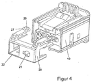
- Figure 4 shows a housing 10 and a slide 20 with apertures 21 and 22 for a preferred embodiment of the invention.
- the aperture 21 is provided for a receiver of an optical fiber.
- the aperture 22 on the other hand is provided for electrical, contact units.
- a locking projection 27 and a two-part latch 25 are also formed on the slide 20, the function of which will be described hereinafter.
- the slide 20 is preferably produced as a separate part and inserted into the housing 10.
- Figure 5 shows the slide 20 having an end face 210, side walls 201 to 204 and guide elements 221 to 224.
- additional parts 25 to 28 of a locking device and a latch nose 29 are shown, the function of which will be described with reference to Figures 9 to 11.
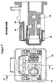
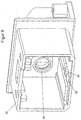
- Figure 6 shows the plug of the connector arrangement from Figure 4 in its unmated state wherein the slide 20 with its openings 21 and 22 are arranged in a starting position on the housing 10.
- Figure 8 shows a sectional drawing along a section 8-8 of Figure 7 illustrating how the slide 20 is held in the housing 10.
- the slide 20 is locked by a housing latch 14 and a part of the latch 25 designed as a projection in the housing 10.
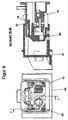
- a mating plug for a connector arrangement with an associated plug according to Figure 6 is shown in Figure 9.
- the mating plug 30 comprises a receiver 31 for an optical fiber and the optical fiber of the plug or its receiver, and a latch 32 and a projection 33.
- the mating plug can, in addition to the mating unit, not visible in Figure 9, for the electrical contact unit of the plug from Figure 6, be wider in design, in particular with respect to the receiver 31.
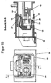
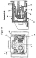
- Figures 10 to 15 show sectional drawings of a mating progression of the connector arrangement with the plug, consisting of the housing 10 and the slide 20, and the mating plug 30. The states shown in the figures are assumed during connection of the mating plug 30 to the plug.
- Figures 14 and 15 show the connector arrangement with plug and mating plug 30 in the mated state.
- the slide 20 is inserted into the housing 10 and the latch 29 is arranged in front of the projection 33.
- the projection 33 and the nose 32 return the slide 20 through the latch 29 into its starting position.
Abstract
Description
- The invention relates to a connector arrangement with a plug and an associated mating plug.
- In addition to connector arrangements with terminal contacts for copper wires, connectors are also known which couple optical fibers to one another. Optical fibers are often used for data transmission when large amounts of data are to be transmitted at high transmission rates or parallel transmission of data on a plurality of channels is desired. The connector arrangement couples an optical fiber and an optical element, for example a further optical fiber or a diode, to one another and conventionally consists of a plug and an associated mating plug.
- Optical fibers are also used, for example, in motor vehicles because of their low sensitivity to interference from electromagnetic radiation. During assembly, maintenance or repair where a plug is in an unmated condition there are various protective devices which may be applied to the plug to protect the optical fibers.
- A known protective device for a connector arrangement is, for example, a protective cap which is removed before connection of the plug to the mating plug. Removal of the cap involves an additional step in the assembly of the connector arrangement and also leads to storage problems with the cap.
- A further protective device is known from US 5,506,922 in the form of a protective flap which can be opened for connection to the optical fiber. The flap opens upon connection of the plug to the mating plug and is a complex mechanism which is susceptible to defects.
- A further common protective device is a collar arranged about the optical fiber which protects the optical fiber and upon connection to the mating plug is connected to the optical element thereof. The collar is, however, only suitable for connecting optical fibers to one another because in the event of connection to a different optical element, the diameter of the collar is too large to obtain a protective effect. A collar can only be designed for connection to an optical element of a certain size.
- An object of the present invention is to provide a simple protective device for a plug in a connector arrangement which is only infrequently susceptible to defects.
- This and other objects are achieved by providing a plug according to the invention for a connector arrangement. The plug and an associated mating plug have a housing which has at least one axial receiver for an optical fiber and a protective device movably mounted in the housing for protecting the optical fiber. The protective device is designed as a slide which can be moved axially to the receiver and has a through aperture for the optical fiber and/or the receiver.
- The protective device can therefore be suitably displaced for a connection to the optical element of the mating plug, wherein the through aperture makes the optical fiber receiver accessible for connection. The slide is also designed simply so as to be only infrequently susceptible to defects.
- The movement direction of the slide preferably corresponds to a plug-in direction in which the plug and mating plug are connected to one another, as a result of which the necessary mechanisms are simplified and therefore have fewer sources of error.
- According to a preferred embodiment of the plug, in a unmated state the slide is located in a starting position in front of the front end of the receiver and in the mated state, the front end of the receiver projects through the aperture. In its starting position, the slide therefore protects the optical fiber in the receiver, but exposes it in the mated state for connection with the optical element the mating plug.
- The invention will be described in more detail hereinafter with the aid of preferred embodiments and with reference to the attached drawings:
- Figure 1 is a three-dimensional view of a preferred embodiment of the plug according to the invention.
- Figure 2 is a three-dimensional view the plug from Figure 1 with a slide in the plugged-in connector arrangement.
- Figure 3 is a three-dimensional view of the plug from Figures 1 and 2, which shows a return device.
- Figure 4 is a three-dimensional exploded drawing of a further embodiment of the plug according to the invention.
- Figure 5 is a three-dimensional view of the slide from Figure 4.
- Figure 6 is a three-dimensional view of the plug from Figure 4 with the plug in an unmated position.
- Figure 7 is an end view of the plug from Figure 4.
- Figure 8 is a section view of the plug taken along the line 8-8 of Figure 7.
- Figure 9 is a three-dimensional view of a mating plug for a plug according to the invention.
- Figure 10 is an end view of the plug and mating plug in engagement during a mating cycle.
- Figure 11 is a sectional view taken along the line 11-11 of Figure 10.
- Figure 12 is an end view of the connector arrangement from Figure 11.
- Figure 13 is a sectional view taken along the line 13-13 of Figure 12 illustrating detachment of the locking. device during the mating cycle.
- Figure 14 is an end view of the connector arrangement from Figure 9.
- Figure 15 is a sectional view taken along the line 15-15 of Figure 14 showing the fully mated position.
-
- Figures 1 to 3 show a preferred embodiment of the invention. A plug of a connector arrangement in Figure 1 has a
housing 10 which has tworeceivers receivers slide 20 in thehousing 10. Theslide 20 can be moved axially with respect to thereceivers apertures - The movement direction of the
slide 20 corresponds to a plug-in direction in which the plug and the mating plug, not shown in this figure, are connected to one another. As Figure 1 shows, theslide 20 is arranged in its starting position in front of the front end of the receiver. - The plug housing and the slide can be made, for example, from plastic material, ceramics or metal.
- Figure 2 shows the plug from Figure 1 with the
slide 20 in a plugged-in or mated condition, wherein theslide 20 is moved with respect to thehousing 10 and itsreceivers apertures - Individual optical fibers or a plurality of optical fibers can be connected to a plug utilising this arrangement. A plug which can be connected to a mating plug in which the most varied of optical elements, for example a further optical fiber, a lens, a filter, a diode or an end piece is mounted, can also be produced.
- In order to prevent the
slide 20 from being pushed unintentionally into thehousing 10, a locking device is provided. As can be seen from Figures 1 and 2, the locking device is designed as alocking tongue 23 of theslide 20. A projection of thelocking tongue 23 rests on ahousing projection 13 to prevent movement of theslide 20 into thehousing 10. Thelocking tongue 23 is arranged so as to extend obliquely in a direction from theslide 20 towards the outside to thehousing 10, so that it can be pressed by a complimentary part of the mating plug (not shown) in the direction of theslide 20 to release the lock. In the mated state, the projection of thelocking tongue 23 is arranged behind thehousing projection 13, as shown in Figure 2. - Figure 3 shows a further preferred embodiment of the plug. The
slide 20 with its throughapertures housing 10. It can be returned into the starting position by a return device, designed as acatch 24, upon detachment of the connector arrangement from a correspondingly shaped part of the mating plug. Thecatch 24 is designed in such a way that movement of the mating plug is not hindered during connection and detachment of the connector arrangement. - Figure 4 shows a
housing 10 and aslide 20 withapertures aperture 21 is provided for a receiver of an optical fiber. Theaperture 22 on the other hand is provided for electrical, contact units. Alocking projection 27 and a two-part latch 25 are also formed on theslide 20, the function of which will be described hereinafter. - The
slide 20 is preferably produced as a separate part and inserted into thehousing 10. - Figure 5 shows the
slide 20 having anend face 210,side walls 201 to 204 and guideelements 221 to 224. In addition to theaperture 21,additional parts 25 to 28 of a locking device and alatch nose 29 are shown, the function of which will be described with reference to Figures 9 to 11. - Figure 6 shows the plug of the connector arrangement from Figure 4 in its unmated state wherein the
slide 20 with itsopenings housing 10. - Figure 8 shows a sectional drawing along a section 8-8 of Figure 7 illustrating how the
slide 20 is held in thehousing 10. Theslide 20 is locked by ahousing latch 14 and a part of thelatch 25 designed as a projection in thehousing 10. - A mating plug for a connector arrangement with an associated plug according to Figure 6 is shown in Figure 9. The
mating plug 30 comprises areceiver 31 for an optical fiber and the optical fiber of the plug or its receiver, and alatch 32 and aprojection 33. The mating plug can, in addition to the mating unit, not visible in Figure 9, for the electrical contact unit of the plug from Figure 6, be wider in design, in particular with respect to thereceiver 31. - Figures 10 to 15 show sectional drawings of a mating progression of the connector arrangement with the plug, consisting of the
housing 10 and theslide 20, and themating plug 30. The states shown in the figures are assumed during connection of themating plug 30 to the plug. - In Figure 9, the plug is attached to the
mating plug 30, but theslide 20 is still locked in thehousing 10. Theslide 20 is blocked by its lockingprojection 27 with ahousing projection 15. - In Figures 12 and 15 the mating plug is connected to the plug to the extent that locking is released. The movement between plug and mating plug 30 is converted via an oblique part of the
latch 25 for release of the locking between the lockingprojection 27 and thehousing projection 15. Thelatch 29 of theslide 20 is arranged in this state between thenose 32 and theprojection 33 of themating plug 30. - Figures 14 and 15 show the connector arrangement with plug and mating plug 30 in the mated state. The
slide 20 is inserted into thehousing 10 and thelatch 29 is arranged in front of theprojection 33. Upon a detachment of the connector arrangement, theprojection 33 and thenose 32 return theslide 20 through thelatch 29 into its starting position. - The configurations and properties of the embodiments described can also be readily combined with one another.
Claims (12)
- A plug for a connector arrangement consisting of a plug and an associated mating plug (30), comprising:characterised in that the protective device is a slide (20) which can be moved axially to the receiver (11, 12) and has a aperture (21, 22) for the optical fiber and/or the receiver (11, 12).a housing (10) which has at least one axial receiver (11, 12) for an optical fiber;a protective device movably mounted in the housing (10) for protecting the optical fiber;
- The plug according to claim 1, characterised in that the movement direction of the slide (20) corresponds to a plug-in direction in which the plug and mating plug (30) are connected to one another.
- Plug according to claim 1 or 2, characterised in that in the slide (20) is arranged in a starting position in front of the front end of the receiver (11, 12) in an unmated state and the front end of the receiver (11, 12) projects through the through aperture (21, 22) in a mated state.
- The plug according to one of claims 1 to 3, characterised in that the slide (20) is produced as a part separate from the housing (10) which can be inserted into the housing (10).
- The plug according to one of claims 1 to 4, characterised in that the slide (20) is designed in the shape of a trough with a front end (210) and side walls (201 to 204) and guide elements (221 to 224) which extend from the front end (210) in the direction of the housing (10).
- The plug according to one of claims 1 to 5, characterised in that the housing (10) comprises two or more axial receivers (11, 12) for a plurality of optical fibers, wherein one optical fiber respectively can be arranged in each receiver (11, 12).
- The plug according to one of claims 1 to 6, characterised by a locking device which restricts movement of the slide (20) in such a way that the protective function of the slide (20) is retained if the plug is not connected to the mating plug (30).
- The plug according to claim 7, characterised in that the locking device is released upon a connection to the mating plug (30) to release the axial movement of the slide (20).
- The plug according to claim 7 or 8, characterised in that the locking device comprises a locking projection (27) which rests against a housing projection (13, 15), wherein the projections (13, 15, 27) can be moved toward one another to release the locking.
- The plug according to one of claims 7 to 9, characterised in that the locking device or the housing (10) contain a part (23, 27) which extends obliquely to the movement direction of the slide (20) and which converts the movement of the mating plug (30) upon connection into a movement to release the lock.
- The plug according to at least claim 3, characterised by a return device which returns the slide (20) into the slide starting position upon detachment of the mating plug (30) from the plug.
- The plug according to claim 11, characterised in that the return device comprises a latch(24, 29) which is arranged on the slide (20) and rests with a correspondingly shaped projection (32, 33) on the mating plug (30) when the connector arrangement is detached.
Applications Claiming Priority (2)
| Application Number | Priority Date | Filing Date | Title |
|---|---|---|---|
| DE10038685 | 2000-08-08 | ||
| DE10038685 | 2000-08-08 |
Publications (2)
| Publication Number | Publication Date |
|---|---|
| EP1180702A1 true EP1180702A1 (en) | 2002-02-20 |
| EP1180702B1 EP1180702B1 (en) | 2008-04-23 |
Family
ID=7651725
Family Applications (1)
| Application Number | Title | Priority Date | Filing Date |
|---|---|---|---|
| EP01118676A Expired - Lifetime EP1180702B1 (en) | 2000-08-08 | 2001-08-03 | Protective device in a connector arrangement for optical fibers |
Country Status (5)
| Country | Link |
|---|---|
| US (1) | US6913393B2 (en) |
| EP (1) | EP1180702B1 (en) |
| JP (1) | JP4756568B2 (en) |
| AT (1) | ATE393407T1 (en) |
| DE (1) | DE60133696T2 (en) |
Cited By (3)
| Publication number | Priority date | Publication date | Assignee | Title |
|---|---|---|---|---|
| EP1598685A1 (en) * | 2004-05-21 | 2005-11-23 | Neutrik Aktiengesellschaft | Device for an optical plug-in connection |
| EP2360802A1 (en) * | 2010-02-22 | 2011-08-24 | Tyco Electronics Raychem BVBA | Protective device and cable termination unit |
| EP2426535A4 (en) * | 2009-04-30 | 2016-06-01 | Adamant Kogyo Co | Optical connector plug |
Families Citing this family (6)
| Publication number | Priority date | Publication date | Assignee | Title |
|---|---|---|---|---|
| US20060040564A1 (en) * | 2004-08-19 | 2006-02-23 | Morrison David S | Block-out cover and removal tool |
| US7680384B2 (en) * | 2006-01-26 | 2010-03-16 | Corning Cable Systems Llc | Installation tool with integrated visual fault indicator for field-installable mechanical splice connector |
| US7993063B2 (en) * | 2009-03-16 | 2011-08-09 | Panduit Corp. | Block-out device for fiber optic adapter |
| US8224146B2 (en) * | 2010-02-05 | 2012-07-17 | Panduit Corp. | Block-out device for fiber optic adapter |
| EP2862094A4 (en) * | 2012-06-19 | 2016-03-02 | Knut Foseide | Protecting connector cover with attaching means |
| US11817667B1 (en) * | 2022-12-28 | 2023-11-14 | Rivian Ip Holdings, Llc | High voltage connector service extraction tool |
Citations (3)
| Publication number | Priority date | Publication date | Assignee | Title |
|---|---|---|---|---|
| US4155159A (en) * | 1976-08-30 | 1979-05-22 | International Telephone And Telegraph Corporation | Tool for connector member |
| EP0613030A2 (en) * | 1993-02-24 | 1994-08-31 | Sumitomo Wiring Systems, Ltd. | Optical fiber connector |
| US5896477A (en) * | 1997-05-16 | 1999-04-20 | Lucent Technologies Inc. | Optical fiber coupling buildout system |
Family Cites Families (6)
| Publication number | Priority date | Publication date | Assignee | Title |
|---|---|---|---|---|
| US4225214A (en) * | 1978-09-18 | 1980-09-30 | Trw Inc. | Connector construction |
| DE68912184T2 (en) * | 1988-04-25 | 1994-07-21 | Whitaker Corp | Plug structure with movable protective cover. |
| US5142598A (en) * | 1991-08-28 | 1992-08-25 | Porta Systems Corp. | Fiber optic connector having snap ring adjustment means |
| JP2797884B2 (en) * | 1992-04-15 | 1998-09-17 | 住友電装株式会社 | Optical fiber connector device |
| US5506922A (en) * | 1994-08-01 | 1996-04-09 | Molex Incorporated | Fiber optic component assembly with a movable protective shield |
| US6315461B1 (en) * | 1999-10-14 | 2001-11-13 | Ocean Design, Inc. | Wet mateable connector |
-
2001
- 2001-08-02 US US09/920,702 patent/US6913393B2/en not_active Expired - Lifetime
- 2001-08-03 AT AT01118676T patent/ATE393407T1/en not_active IP Right Cessation
- 2001-08-03 DE DE60133696T patent/DE60133696T2/en not_active Expired - Lifetime
- 2001-08-03 EP EP01118676A patent/EP1180702B1/en not_active Expired - Lifetime
- 2001-08-07 JP JP2001239277A patent/JP4756568B2/en not_active Expired - Fee Related
Patent Citations (3)
| Publication number | Priority date | Publication date | Assignee | Title |
|---|---|---|---|---|
| US4155159A (en) * | 1976-08-30 | 1979-05-22 | International Telephone And Telegraph Corporation | Tool for connector member |
| EP0613030A2 (en) * | 1993-02-24 | 1994-08-31 | Sumitomo Wiring Systems, Ltd. | Optical fiber connector |
| US5896477A (en) * | 1997-05-16 | 1999-04-20 | Lucent Technologies Inc. | Optical fiber coupling buildout system |
Cited By (4)
| Publication number | Priority date | Publication date | Assignee | Title |
|---|---|---|---|---|
| EP1598685A1 (en) * | 2004-05-21 | 2005-11-23 | Neutrik Aktiengesellschaft | Device for an optical plug-in connection |
| EP1912085A1 (en) * | 2004-05-21 | 2008-04-16 | Neutrik Aktiengesellschaft | Device for an optical plug connector |
| EP2426535A4 (en) * | 2009-04-30 | 2016-06-01 | Adamant Kogyo Co | Optical connector plug |
| EP2360802A1 (en) * | 2010-02-22 | 2011-08-24 | Tyco Electronics Raychem BVBA | Protective device and cable termination unit |
Also Published As
| Publication number | Publication date |
|---|---|
| EP1180702B1 (en) | 2008-04-23 |
| US20040197053A1 (en) | 2004-10-07 |
| DE60133696D1 (en) | 2008-06-05 |
| US6913393B2 (en) | 2005-07-05 |
| JP4756568B2 (en) | 2011-08-24 |
| DE60133696T2 (en) | 2009-07-09 |
| JP2002090577A (en) | 2002-03-27 |
| ATE393407T1 (en) | 2008-05-15 |
Similar Documents
| Publication | Publication Date | Title |
|---|---|---|
| US6491542B1 (en) | Combined connection and terminal position assurance structure for vehicle wiring connectors | |
| US6762940B2 (en) | Pluggable optical transceiver with push-pull actuator release collar | |
| EP0117022B1 (en) | Fiber optic connector assembly | |
| US6357931B1 (en) | Hybrid connector | |
| US8169783B2 (en) | Latch assembly for a pluggable electronic module | |
| US7419313B2 (en) | Optoelectronic device in combination with a push-in cage | |
| US6926551B1 (en) | Pluggable transceiver latching mechanism | |
| CN113258355B (en) | Connector assembly | |
| EP1182478B1 (en) | Optical connector having a combined guide pin lock and grounding contact | |
| US6885560B2 (en) | Pluggable optical transceiver with push-pull actuator handle | |
| US5993255A (en) | Electrical connector with combination terminal guide and terminal position assurance member | |
| GB2341455A (en) | Cylindrical contact for fibre optic connector having parallelepiped shaped ferrule | |
| JPH0774848B2 (en) | Connector assembly for optical fiber | |
| US8764312B2 (en) | Optical connector plug having improved latching mechanism | |
| CN1319221C (en) | Protection device for plug-in connection | |
| EP1092995A2 (en) | Optical connector having multiple modular housings | |
| US9086546B2 (en) | Connector systems having receptacle assembly and plug assembly | |
| US6913393B2 (en) | Protective device in a connector arrangement for optical fibers | |
| US6527578B2 (en) | Connector fitting structure | |
| US6457872B1 (en) | Optical waveguide plug connector for a mechanically releasable connection between at least one OWG connector pair and a mating connector | |
| JP5892600B2 (en) | Connector device | |
| US6364686B2 (en) | Electrical and/or optical connector with a latching arm | |
| CN109698438B (en) | Shielded connector and shielded connector system | |
| JP3417846B2 (en) | Connector having shield member | |
| EP1102099A2 (en) | Hybrid connector |
Legal Events
| Date | Code | Title | Description |
|---|---|---|---|
| PUAI | Public reference made under article 153(3) epc to a published international application that has entered the european phase |
Free format text: ORIGINAL CODE: 0009012 |
|
| AK | Designated contracting states |
Kind code of ref document: A1 Designated state(s): AT BE CH CY DE DK ES FI FR GB GR IE IT LI LU MC NL PT SE TR |
|
| AX | Request for extension of the european patent |
Free format text: AL;LT;LV;MK;RO;SI |
|
| 17P | Request for examination filed |
Effective date: 20020724 |
|
| AKX | Designation fees paid |
Free format text: AT BE CH CY DE DK ES FI FR GB GR IE IT LI LU MC NL PT SE TR |
|
| GRAC | Information related to communication of intention to grant a patent modified |
Free format text: ORIGINAL CODE: EPIDOSCIGR1 |
|
| GRAP | Despatch of communication of intention to grant a patent |
Free format text: ORIGINAL CODE: EPIDOSNIGR1 |
|
| RIN1 | Information on inventor provided before grant (corrected) |
Inventor name: BUCK, CARSTEN Inventor name: REIFEL, DIRK Inventor name: FERSTL, MICHAEL Inventor name: LOEFFELHOLZ, STEFAN |
|
| GRAS | Grant fee paid |
Free format text: ORIGINAL CODE: EPIDOSNIGR3 |
|
| GRAA | (expected) grant |
Free format text: ORIGINAL CODE: 0009210 |
|
| AK | Designated contracting states |
Kind code of ref document: B1 Designated state(s): AT BE CH CY DE DK ES FI FR GB GR IE IT LI LU MC NL PT SE TR |
|
| REG | Reference to a national code |
Ref country code: GB Ref legal event code: FG4D |
|
| REG | Reference to a national code |
Ref country code: CH Ref legal event code: EP |
|
| REF | Corresponds to: |
Ref document number: 60133696 Country of ref document: DE Date of ref document: 20080605 Kind code of ref document: P |
|
| REG | Reference to a national code |
Ref country code: IE Ref legal event code: FG4D Free format text: LANGUAGE OF EP DOCUMENT: FRENCH |
|
| NLV1 | Nl: lapsed or annulled due to failure to fulfill the requirements of art. 29p and 29m of the patents act | ||
| PG25 | Lapsed in a contracting state [announced via postgrant information from national office to epo] |
Ref country code: FI Free format text: LAPSE BECAUSE OF FAILURE TO SUBMIT A TRANSLATION OF THE DESCRIPTION OR TO PAY THE FEE WITHIN THE PRESCRIBED TIME-LIMIT Effective date: 20080423 Ref country code: NL Free format text: LAPSE BECAUSE OF FAILURE TO SUBMIT A TRANSLATION OF THE DESCRIPTION OR TO PAY THE FEE WITHIN THE PRESCRIBED TIME-LIMIT Effective date: 20080423 Ref country code: ES Free format text: LAPSE BECAUSE OF FAILURE TO SUBMIT A TRANSLATION OF THE DESCRIPTION OR TO PAY THE FEE WITHIN THE PRESCRIBED TIME-LIMIT Effective date: 20080803 Ref country code: PT Free format text: LAPSE BECAUSE OF FAILURE TO SUBMIT A TRANSLATION OF THE DESCRIPTION OR TO PAY THE FEE WITHIN THE PRESCRIBED TIME-LIMIT Effective date: 20080923 |
|
| PG25 | Lapsed in a contracting state [announced via postgrant information from national office to epo] |
Ref country code: AT Free format text: LAPSE BECAUSE OF FAILURE TO SUBMIT A TRANSLATION OF THE DESCRIPTION OR TO PAY THE FEE WITHIN THE PRESCRIBED TIME-LIMIT Effective date: 20080423 |
|
| PG25 | Lapsed in a contracting state [announced via postgrant information from national office to epo] |
Ref country code: DK Free format text: LAPSE BECAUSE OF FAILURE TO SUBMIT A TRANSLATION OF THE DESCRIPTION OR TO PAY THE FEE WITHIN THE PRESCRIBED TIME-LIMIT Effective date: 20080423 Ref country code: SE Free format text: LAPSE BECAUSE OF FAILURE TO SUBMIT A TRANSLATION OF THE DESCRIPTION OR TO PAY THE FEE WITHIN THE PRESCRIBED TIME-LIMIT Effective date: 20080723 |
|
| ET | Fr: translation filed | ||
| PG25 | Lapsed in a contracting state [announced via postgrant information from national office to epo] |
Ref country code: BE Free format text: LAPSE BECAUSE OF FAILURE TO SUBMIT A TRANSLATION OF THE DESCRIPTION OR TO PAY THE FEE WITHIN THE PRESCRIBED TIME-LIMIT Effective date: 20080423 |
|
| PLBE | No opposition filed within time limit |
Free format text: ORIGINAL CODE: 0009261 |
|
| STAA | Information on the status of an ep patent application or granted ep patent |
Free format text: STATUS: NO OPPOSITION FILED WITHIN TIME LIMIT |
|
| PG25 | Lapsed in a contracting state [announced via postgrant information from national office to epo] |
Ref country code: MC Free format text: LAPSE BECAUSE OF NON-PAYMENT OF DUE FEES Effective date: 20080831 |
|
| REG | Reference to a national code |
Ref country code: CH Ref legal event code: PL |
|
| 26N | No opposition filed |
Effective date: 20090126 |
|
| PG25 | Lapsed in a contracting state [announced via postgrant information from national office to epo] |
Ref country code: LI Free format text: LAPSE BECAUSE OF NON-PAYMENT OF DUE FEES Effective date: 20080831 Ref country code: CH Free format text: LAPSE BECAUSE OF NON-PAYMENT OF DUE FEES Effective date: 20080831 |
|
| PG25 | Lapsed in a contracting state [announced via postgrant information from national office to epo] |
Ref country code: IE Free format text: LAPSE BECAUSE OF NON-PAYMENT OF DUE FEES Effective date: 20080803 |
|
| PG25 | Lapsed in a contracting state [announced via postgrant information from national office to epo] |
Ref country code: LU Free format text: LAPSE BECAUSE OF NON-PAYMENT OF DUE FEES Effective date: 20080803 Ref country code: CY Free format text: LAPSE BECAUSE OF FAILURE TO SUBMIT A TRANSLATION OF THE DESCRIPTION OR TO PAY THE FEE WITHIN THE PRESCRIBED TIME-LIMIT Effective date: 20080423 |
|
| PG25 | Lapsed in a contracting state [announced via postgrant information from national office to epo] |
Ref country code: TR Free format text: LAPSE BECAUSE OF FAILURE TO SUBMIT A TRANSLATION OF THE DESCRIPTION OR TO PAY THE FEE WITHIN THE PRESCRIBED TIME-LIMIT Effective date: 20080423 |
|
| PG25 | Lapsed in a contracting state [announced via postgrant information from national office to epo] |
Ref country code: GR Free format text: LAPSE BECAUSE OF FAILURE TO SUBMIT A TRANSLATION OF THE DESCRIPTION OR TO PAY THE FEE WITHIN THE PRESCRIBED TIME-LIMIT Effective date: 20080724 |
|
| REG | Reference to a national code |
Ref country code: DE Ref legal event code: R082 Ref document number: 60133696 Country of ref document: DE Representative=s name: MARKS & CLERK (LUXEMBOURG) LLP, LU Ref country code: DE Ref legal event code: R081 Ref document number: 60133696 Country of ref document: DE Owner name: TE CONNECTIVITY GERMANY GMBH, DE Free format text: FORMER OWNER: TYCO ELECTRONICS AMP GMBH, 64625 BENSHEIM, DE |
|
| REG | Reference to a national code |
Ref country code: FR Ref legal event code: PLFP Year of fee payment: 15 |
|
| REG | Reference to a national code |
Ref country code: FR Ref legal event code: CD Owner name: TE CONNECTIVITY GERMANY GMBH Effective date: 20151027 |
|
| REG | Reference to a national code |
Ref country code: FR Ref legal event code: PLFP Year of fee payment: 16 |
|
| REG | Reference to a national code |
Ref country code: FR Ref legal event code: PLFP Year of fee payment: 17 |
|
| REG | Reference to a national code |
Ref country code: FR Ref legal event code: PLFP Year of fee payment: 18 |
|
| PGFP | Annual fee paid to national office [announced via postgrant information from national office to epo] |
Ref country code: FR Payment date: 20180612 Year of fee payment: 18 |
|
| PGFP | Annual fee paid to national office [announced via postgrant information from national office to epo] |
Ref country code: IT Payment date: 20180823 Year of fee payment: 18 |
|
| PGFP | Annual fee paid to national office [announced via postgrant information from national office to epo] |
Ref country code: GB Payment date: 20180801 Year of fee payment: 18 |
|
| GBPC | Gb: european patent ceased through non-payment of renewal fee |
Effective date: 20190803 |
|
| PG25 | Lapsed in a contracting state [announced via postgrant information from national office to epo] |
Ref country code: FR Free format text: LAPSE BECAUSE OF NON-PAYMENT OF DUE FEES Effective date: 20190831 |
|
| PG25 | Lapsed in a contracting state [announced via postgrant information from national office to epo] |
Ref country code: IT Free format text: LAPSE BECAUSE OF NON-PAYMENT OF DUE FEES Effective date: 20190803 Ref country code: GB Free format text: LAPSE BECAUSE OF NON-PAYMENT OF DUE FEES Effective date: 20190803 |
|
| PGFP | Annual fee paid to national office [announced via postgrant information from national office to epo] |
Ref country code: DE Payment date: 20200722 Year of fee payment: 20 |
|
| REG | Reference to a national code |
Ref country code: DE Ref legal event code: R071 Ref document number: 60133696 Country of ref document: DE |