EP1180620A2 - Cylinder head gasket with partial seal coating - Google Patents
Cylinder head gasket with partial seal coating Download PDFInfo
- Publication number
- EP1180620A2 EP1180620A2 EP01117653A EP01117653A EP1180620A2 EP 1180620 A2 EP1180620 A2 EP 1180620A2 EP 01117653 A EP01117653 A EP 01117653A EP 01117653 A EP01117653 A EP 01117653A EP 1180620 A2 EP1180620 A2 EP 1180620A2
- Authority
- EP
- European Patent Office
- Prior art keywords
- beads
- holes
- cylinder head
- area
- metal plate
- Prior art date
- Legal status (The legal status is an assumption and is not a legal conclusion. Google has not performed a legal analysis and makes no representation as to the accuracy of the status listed.)
- Granted
Links
Images



Classifications
-
- F—MECHANICAL ENGINEERING; LIGHTING; HEATING; WEAPONS; BLASTING
- F02—COMBUSTION ENGINES; HOT-GAS OR COMBUSTION-PRODUCT ENGINE PLANTS
- F02F—CYLINDERS, PISTONS OR CASINGS, FOR COMBUSTION ENGINES; ARRANGEMENTS OF SEALINGS IN COMBUSTION ENGINES
- F02F11/00—Arrangements of sealings in combustion engines
-
- F—MECHANICAL ENGINEERING; LIGHTING; HEATING; WEAPONS; BLASTING
- F16—ENGINEERING ELEMENTS AND UNITS; GENERAL MEASURES FOR PRODUCING AND MAINTAINING EFFECTIVE FUNCTIONING OF MACHINES OR INSTALLATIONS; THERMAL INSULATION IN GENERAL
- F16J—PISTONS; CYLINDERS; SEALINGS
- F16J15/00—Sealings
- F16J15/02—Sealings between relatively-stationary surfaces
- F16J15/06—Sealings between relatively-stationary surfaces with solid packing compressed between sealing surfaces
- F16J15/08—Sealings between relatively-stationary surfaces with solid packing compressed between sealing surfaces with exclusively metal packing
- F16J15/0818—Flat gaskets
-
- F—MECHANICAL ENGINEERING; LIGHTING; HEATING; WEAPONS; BLASTING
- F16—ENGINEERING ELEMENTS AND UNITS; GENERAL MEASURES FOR PRODUCING AND MAINTAINING EFFECTIVE FUNCTIONING OF MACHINES OR INSTALLATIONS; THERMAL INSULATION IN GENERAL
- F16J—PISTONS; CYLINDERS; SEALINGS
- F16J15/00—Sealings
- F16J15/02—Sealings between relatively-stationary surfaces
- F16J15/06—Sealings between relatively-stationary surfaces with solid packing compressed between sealing surfaces
- F16J15/08—Sealings between relatively-stationary surfaces with solid packing compressed between sealing surfaces with exclusively metal packing
- F16J15/0818—Flat gaskets
- F16J15/0825—Flat gaskets laminated
-
- F—MECHANICAL ENGINEERING; LIGHTING; HEATING; WEAPONS; BLASTING
- F16—ENGINEERING ELEMENTS AND UNITS; GENERAL MEASURES FOR PRODUCING AND MAINTAINING EFFECTIVE FUNCTIONING OF MACHINES OR INSTALLATIONS; THERMAL INSULATION IN GENERAL
- F16J—PISTONS; CYLINDERS; SEALINGS
- F16J15/00—Sealings
- F16J15/02—Sealings between relatively-stationary surfaces
- F16J15/06—Sealings between relatively-stationary surfaces with solid packing compressed between sealing surfaces
- F16J15/08—Sealings between relatively-stationary surfaces with solid packing compressed between sealing surfaces with exclusively metal packing
- F16J15/0818—Flat gaskets
- F16J2015/0856—Flat gaskets with a non-metallic coating or strip
Definitions
- the present invention relates to a cylinder head gasket with partial seal coatings around the holes for the cylinder bores for securely sealing around the same.
- a cylinder head gasket 11 with a plurality of holes for the cylinder bores for sealing between a cylinder head and a cylinder block includes on a plate 20 holes 13 for the cylinder bores, oil holes 15, water holes 16, and bolt holes 17, 18. Also, in order to seal combustion gases generated in the combustion chambers, oil circulating through an oil gallery and water in a water jacket, the gasket 11 includes sealing means, such as beads 12 and seal rings 14, for providing adequate sealing pressures for the respective holes to be sealed.
- the metal plate 20 superior to mechanical strength and durability is used, and beads 12 for forming main sealing portions are arranged around the holes 13 for the cylinder bores to obtain high sealing characteristics by the beads 12.
- bolt holes 17, 18 head bolts (not shown) are inserted, and the gasket is sandwiched between the cylinder head and the cylinder block (not shown) and is tightened by the head bolts.
- the bolt holes 17, 18 are arranged to surround the holes 13 for the cylinder bores to securely seal around the cylinder bores.
- the tightening pressures by the bolts passing through the bolt holes 17 are applied to the areas or ranges A in Fig. 8, while the tightening pressures by the bolts passing through the bolt holes 18 are applied to the areas B in Fig. 8.
- the surface pressures are formed by tightening the bolts.
- the bolts are tightened according to the predetermined order.
- the bolts are tightened by a torque wrench to the predetermined torque.
- the sealing area B to which the tightening forces of the bolts passing through the bolt holes 18 are applied is very small as compared to the area A to which the tightening forces of the bolts passing through the bolt holes 17. Therefore, the surface pressures acted on the area A become very small relative to the surface pressures acted on the area B.
- the holes 13 for the cylinder bores are arranged as close as possible.
- the area W between the holes 13 for the cylinder bores comes a severe condition. Namely, in the area W, heat load is high, and combustions of gases different in timing are repeated in the adjacent cylinder bores. Therefore, the beads 12 are likely to cause creep relaxation and damages, so that gas leakage may happen.
- an auxiliary bead is formed adjacent to a main bead, and a stopper formed of a metal shim is provided to thereby prevent creep relaxation of the bead.
- the metal shim is very thin, i.e. generally 30-100 ⁇ m, which is required to be processed precisely and sandwiched between plates or fixed to a plate. Therefore, there are troubles of taking time for processing the shim and storage to cause high cost.
- the metal shim does not have compressibility, and there is no thin metal shim less than 30 ⁇ m. Therefore, in case the shim is used, there are steps at the ends of the shim to form large difference in surface pressures.
- the present invention has been made to obviate these problems, and an object of the invention is to provide a cylinder head gasket, wherein the surface pressures of the beads situated between the holes for the adjacent cylinder bores are reinforced to improve the sealing characteristics.
- Another object of the invention is to provide a cylinder head gasket as stated above, wherein creep relaxation and damage of the beads are prevented to enhance the durability of the gasket.
- a cylinder head gasket of the invention is used for an internal combustion engine with a plurality of cylinder bores.
- the gasket is formed of a first metal plate extending substantially throughout an entire area to be sealed.
- the first metal plate includes a plurality of holes corresponding to the cylinder bores of the engine, a plurality of beads surrounding the respective holes for the cylinder bores, and at least one area situated between the holes adjacent to each other.
- Seal coatings are deposited above the beads in the at least one area.
- the seal coating has heatproof characteristic, i.e. strong against heat, and compressibility to strengthen the surface pressure of the beads at the at least one area.
- the seal coating may be selected from the group consisting of epoxy resin, phenol resin, phenoxy resin, fluoroplastics and polyamideimido.
- a desired shape of the seal coating may be applied by screen printing or spraying with a mask.
- the seal coating may have one layer or a plurality of layers. Especially, phenoxy resin has heat resistance over 200 °C, and in view of working ability and coating characteristics, phenoxy resin is most preferable.
- the gasket has the coatings with heat resistance, which are applied to the area between the adjacent holes for the cylinder bores to be subjected to the severe condition where the tightening strength is low.
- the surface pressures of the beads applied to the area between the holes for the cylinder bores can be reinforced by the coatings with the compressibility. In this reinforcement of the surface pressures, the sealing pressures are increased to have the pressures substantially the same as those in the end areas of the holes for the cylinder bores. Therefore, the sealing can be made securely.
- reaction forces of the cylinder head and the surface pressures applied to the beads between the holes for the cylinder bores are reduced or relieved, so that the creep relaxation and damage of the beads to which the coatings are applied are prevented.
- an adequate sealing pressure can be formed at the inner cylinder by the adequate sealing pressures for the cylinders at the longitudinal ends of the engine. Thus, it does not require a large tightening torque, so that the creep relaxation and damage of the beads are prevented.
- the coatings are made by a screen printing, even if the coatings have complicated shapes, the coatings can be made easily. Further, the thickness of the coating can be changed easily by multiple printings, and the coating with an adequate thickness can be formed easily.
- the gasket of the invention may be formed of one or a plurality of metal plates. Also, in addition to the above coating, the gasket may have another coating, such as seal coating formed at an outer periphery of the gasket.
- the seal coatings deposited above the beads in one area are integrally connected together as one unit.
- the seal coatings may be entirely deposited on the first metal plate between the beads.
- the seal coatings are applied on the metal plate.
- the seal coatings may be applied on the another metal plate facing the beads.
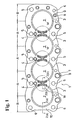
- a cylinder head gasket 1 for an engine with a plurality of cylinder chambers is designed to seal combustion chambers arranged linearly.
- the gasket 1 includes a base plate 10 having therein holes, such as holes 2 for cylinder bores, oil holes 7, water waters 8, bolt holes 5, 6.
- the base plate 10 includes beads 3 around the peripheries of the holes 2 for the cylinder bore, and seal rings 9 around the peripheries of the oil holes 7 and water holes 8.
- bolts (not shown) are inserted after the cylinder head gasket is sandwiched between a cylinder head and a cylinder block (both not shown), and the bolts are tightened.
- the bolt holes 5, 6 are generally arranged around the holes 2 for securely sealing around the cylinder bores.
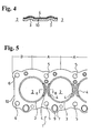
- Coatings 4 having heatproof characteristic and compressibility are applied to bead portions at areas W between the holes 2 for the cylinder bores. Namely, as shown in Figs. 1 and 2(b), the coatings 4 are formed at the beads in the areas W while connecting the two coatings 4 at a narrow portion. In an embodiment as shown in Figs. 3 and 4, the coatings 4 with two layers are formed at the beads in the areas W while connecting the two coatings at a wide portion. In an embodiment as shown in Figs. 5 and 6, the coatings 4 are formed on the beads in the area W without a connection.
- the coatings may have a single layer or a plurality of layers.
- the coatings 4 are formed on the side of the projections of the beads 3.
- the coating 4' may be formed on the metal plate 10a contacting the bead 3 instead of the metal plate 10b, as shown in Figs. 7(a) and 7(b).
- the coating 4' may be formed on the metal plate 10a at a side opposite to the bead 3 or on the metal plate 10c at a side opposite to the bead 3.
- the base plate 10 for the gasket 1 may be formed of a hard metal plate, such as stainless steel or spring steel, or soft steel plate.
- the seal coating 4 or 4' is formed to have a hardness and thickness such that when the coating is compressed, the coating is deformed by not damaged.
- the seal coating may be formed of epoxy resin, phenol resin, phenoxy resin, fluoroplastics and polyamideimido.
- the sealing coatings are formed at the desired shapes by screen printing. In view of the operation ability and physical characteristics, phenoxy resin is preferable.
- the coating may have a hardness of F6-6H in pencil hardness and a thickness of 5-150 ⁇ m, according to the kind and size of the engine.
- the coating may be applied by spraying and so on.
- the thickness may be changed easily by multiple printing, so that the gasket can be manufactured easily.
- a resilient coating formed of rubber material may be applied on the entire surface of the gasket including the coating 4.
- the material may be a rubber type material, such as NBR gum, fluorine rubber, silicone rubber, hydrogen added nitrilebutadiene rubber.
- the coatings 4 are formed on the beads 3 between the holes 2 for the cylinder bores. Therefore, the surface pressure is reinforced at the area W where the tightening pressure is relatively low, and it is possible to provide the sealing pressure at the area W of the beads 3 located between the holes 2 for the cylinder bores with substantially the same sealing pressure of the bead 3 outside the area W.
- the area for tightening by one bolt in the bolt hole 5 is greater than the area for tightening by one bolt disposed in the bolt hole 6 in the end area B.
- the initial pressure for the beads 3 at the area between the holes 2 for the cylinder bores is low.
- the surface pressures are increased by the thickness of the coatings 4, the sealing ability at the area W is improved.
- the beads 3 at the area W are protected by the compressibility of the coatings 4, the creep relaxation and damage of the beads 3 can be prevented.
- a sealing pressure applied to the area W between the holes 2 for the cylinder bores can be increased without requiring a large tightening pressure, so that large sealing pressures need not be applied to the beads 3 at the end areas B. Therefore, the creep relaxation and damage of the beads 3 at the end areas B can be prevented to thereby improve the durability.
- the coatings are applied to the portions of the beads 3 adjacent to each other between the holes for the cylinder bores, the surface pressure can be reinforced at the portions where the tightening pressure is relatively small.
- the sealing pressure which is substantially the same as that for the beads at the end areas can be applied to the beads at the area between the holes for the cylinder bores.
- the bead can be protected by the compressibility of the coating, the creep relaxation of the bead and the damage thereof can be prevented.
- the sealing pressures applied to the beads at the area between the holes for the cylinder bores can be increased without requiring the large tightening force, large sealing pressures need not be applied to the beads at the end areas. Therefore, the creep relaxation and the damage of the beads at the end areas can be prevented.
- the surface pressure can be reinforced at the area between the holes for the cylinder bores where the sealing pressures are likely to decrease, to thereby provide the cylinder head gasket with improved sealing ability and durability.
- the coating can be coated repeatedly at the bead, so that the coating can be provided easily for the head gasket with the limited areas. Also, in comparing with the processing for the shim, since the coating can be easily applied by printing or spraying, the management of the parts and processing can be made easily. Also, the steps for manufacturing the gasket can be decreased and the manufacturing cost can be reduced.
Landscapes
- Engineering & Computer Science (AREA)
- General Engineering & Computer Science (AREA)
- Mechanical Engineering (AREA)
- Chemical & Material Sciences (AREA)
- Combustion & Propulsion (AREA)
- Gasket Seals (AREA)
Abstract
Description
Claims (6)
- A cylinder head gasket (1) for an internal combustion engine with a plurality of cylinder bores, comprising:wherein said seal coatings (4, 4') deposited above the beads are located only in the at least one area to strengthen surface pressure of the beads at the at least one area.a first metal plate (10, 10b) extending substantially throughout an entire area to be sealed, said first metal plate having a plurality of holes (2) corresponding to the cylinder bores of the engine, a plurality of beads (3) surrounding the respective holes, and at least one area (W) situated between the holes adjacent to each other, andseal coatings (4, 4') deposited above the beads and having heatproof characteristic and compressibility,
- A cylinder head gasket (1) according to claim 1, wherein said seal coatings (4, 4') deposited above the beads (3) and located adjacent to each other are integrally connected together as one unit.
- A cylinder head gasket (1) according to claim 1 or 2, wherein said seal coatings (4, 4') are entirely deposited on the first metal plate between the beads.
- A cylinder head gasket (1) according to claim 3, wherein said seal coatings (4) are coated on the first metal plate (10).
- A cylinder head gasket according to any one of claims 1 to 3, further comprising a second metal plate (10a) disposed on the first metal plate (10b) at a side where the beads project, said seal coatings (4') being coated on the second metal plate (10a) facing the beads.
- A cylinder head gasket (1) according to any one of claims 1 to 5, wherein said seal coating (4, 4') is selected from the group consisting of epoxy resin, phenol resin, phenoxy resin, fluoroplastics and polyamideimido.
Applications Claiming Priority (2)
| Application Number | Priority Date | Filing Date | Title |
|---|---|---|---|
| JP2000238757A JP3753413B2 (en) | 2000-08-07 | 2000-08-07 | Multi-cylinder head gasket |
| JP2000238757 | 2000-08-07 |
Publications (3)
| Publication Number | Publication Date |
|---|---|
| EP1180620A2 true EP1180620A2 (en) | 2002-02-20 |
| EP1180620A3 EP1180620A3 (en) | 2004-01-07 |
| EP1180620B1 EP1180620B1 (en) | 2005-09-14 |
Family
ID=18730409
Family Applications (1)
| Application Number | Title | Priority Date | Filing Date |
|---|---|---|---|
| EP01117653A Expired - Lifetime EP1180620B1 (en) | 2000-08-07 | 2001-07-25 | Cylinder head gasket with partial seal coating |
Country Status (5)
| Country | Link |
|---|---|
| US (1) | US6517084B2 (en) |
| EP (1) | EP1180620B1 (en) |
| JP (1) | JP3753413B2 (en) |
| KR (1) | KR100411388B1 (en) |
| DE (1) | DE60113349T2 (en) |
Cited By (1)
| Publication number | Priority date | Publication date | Assignee | Title |
|---|---|---|---|---|
| CN102797588A (en) * | 2012-08-20 | 2012-11-28 | 烟台福尔福密封垫板有限公司 | Coated internal combustion engine cylinder sealing liner plate |
Families Citing this family (18)
| Publication number | Priority date | Publication date | Assignee | Title |
|---|---|---|---|---|
| US6945538B2 (en) * | 2001-10-26 | 2005-09-20 | Freudenberg-Nok General Partnership | Cylinder head gasket and method of producing |
| JP2005155667A (en) * | 2003-11-20 | 2005-06-16 | Nippon Packing Kogyo Kk | Gasket |
| KR100790274B1 (en) * | 2003-12-22 | 2007-12-31 | 동부일렉트로닉스 주식회사 | Semiconductor Wafer Cleaning Equipment |
| JP4155357B2 (en) * | 2004-02-04 | 2008-09-24 | 石川ガスケット株式会社 | Cylinder head gasket |
| US7344796B2 (en) * | 2004-02-18 | 2008-03-18 | Freudenberg-Nok General Partnership | Fluoroelastomer gasket compositions |
| US20050187331A1 (en) * | 2004-02-20 | 2005-08-25 | Yuan Hui L. | Fluoroelastomer gasket compositions |
| US20050187325A1 (en) * | 2004-02-20 | 2005-08-25 | Yuan Hui L. | Silicone gasket compositions |
| JP4256402B2 (en) * | 2006-05-12 | 2009-04-22 | 石川ガスケット株式会社 | gasket |
| US8960681B2 (en) | 2008-07-17 | 2015-02-24 | Nippon Gasket Co., Ltd. | Cylinder head gasket |
| JP5061204B2 (en) * | 2010-01-07 | 2012-10-31 | 株式会社豊田自動織機 | Cylinder head gasket |
| CN101798969A (en) * | 2010-04-01 | 2010-08-11 | 重庆长安汽车股份有限公司 | Engine cylinder head sealing gasket |
| JP2012007479A (en) * | 2010-06-22 | 2012-01-12 | Nichias Corp | Heat retention member for cylinder bore wall, internal combustion engine and automobile |
| JP5397347B2 (en) * | 2010-08-06 | 2014-01-22 | 日本ガスケット株式会社 | Cylinder head gasket and manufacturing method thereof |
| US8500131B2 (en) * | 2010-12-02 | 2013-08-06 | Dana Automotive Systems Group, Llc | Exhaust manifold gasket |
| US20130106063A1 (en) * | 2011-11-02 | 2013-05-02 | Dana Automotive Systems Group, Llc | Multi-Layer Inserts for Gaskets |
| US20130106065A1 (en) * | 2011-11-02 | 2013-05-02 | Dana Automotive Systems Group, Llc | Multi-Layer Inserts for Gaskets |
| US9939066B2 (en) | 2013-03-14 | 2018-04-10 | Federal-Mogul Llc | Elastic sealing member radially inwardly of primary sealing bead |
| WO2019130561A1 (en) * | 2017-12-28 | 2019-07-04 | 本田技研工業株式会社 | Seal structure for internal combustion engine |
Family Cites Families (13)
| Publication number | Priority date | Publication date | Assignee | Title |
|---|---|---|---|---|
| DE3425075A1 (en) * | 1984-07-07 | 1986-01-16 | Goetze Ag, 5093 Burscheid | Cylinder head gasket for internal combustion engines and a method for its production |
| US4688809A (en) * | 1985-11-26 | 1987-08-25 | Cummins Engine Company, Inc. | Gasket for internal combustion engine |
| DE3922284A1 (en) * | 1989-07-06 | 1991-01-17 | Reinz Dichtungs Gmbh | CYLINDER HEAD GASKET |
| EP0468526B1 (en) * | 1990-07-26 | 1995-04-05 | Taiho Kogyo Co., Ltd. | Metal gasket |
| JP2844501B2 (en) * | 1991-08-21 | 1999-01-06 | 日本ガスケット株式会社 | Metal gasket and manufacturing method thereof |
| US5267740A (en) * | 1992-02-20 | 1993-12-07 | Fel-Pro Incorporated | Metal head gasket with integrated sealing aids |
| EP0580427B1 (en) * | 1992-07-21 | 1996-09-04 | Ishikawa Gasket Co. Ltd. | Metal laminate gasket with recess and flange |
| JP3322765B2 (en) * | 1994-11-21 | 2002-09-09 | 国産部品工業株式会社 | Metal gasket |
| US5951021A (en) * | 1994-11-22 | 1999-09-14 | Japan Metal Gasket Co., Ltd. | Metallic gasket |
| US5938208A (en) * | 1994-12-30 | 1999-08-17 | Kokusan Parts Industry Co., Ltd. | Separate plate placed between adjacent valve bodies in a control valve unit of an automatic transmission |
| US5769430A (en) * | 1996-09-30 | 1998-06-23 | Ishikawa Gasket Co., Ltd. | Metal gasket with bead and thermal sprayed layer thereof |
| JP3273752B2 (en) * | 1997-11-11 | 2002-04-15 | 石川ガスケット株式会社 | Gasket sealing method |
| FR2774430B1 (en) * | 1998-02-05 | 2000-04-21 | Curty Payen Sa | CYLINDER HEAD GASKET FOR INTERNAL COMBUSTION ENGINE |
-
2000
- 2000-08-07 JP JP2000238757A patent/JP3753413B2/en not_active Expired - Fee Related
-
2001
- 2001-06-29 US US09/893,902 patent/US6517084B2/en not_active Expired - Fee Related
- 2001-07-07 KR KR10-2001-0040591A patent/KR100411388B1/en not_active Expired - Fee Related
- 2001-07-25 DE DE60113349T patent/DE60113349T2/en not_active Expired - Fee Related
- 2001-07-25 EP EP01117653A patent/EP1180620B1/en not_active Expired - Lifetime
Non-Patent Citations (1)
| Title |
|---|
| None |
Cited By (1)
| Publication number | Priority date | Publication date | Assignee | Title |
|---|---|---|---|---|
| CN102797588A (en) * | 2012-08-20 | 2012-11-28 | 烟台福尔福密封垫板有限公司 | Coated internal combustion engine cylinder sealing liner plate |
Also Published As
| Publication number | Publication date |
|---|---|
| DE60113349D1 (en) | 2005-10-20 |
| DE60113349T2 (en) | 2006-01-12 |
| KR20020012484A (en) | 2002-02-16 |
| KR100411388B1 (en) | 2003-12-18 |
| EP1180620B1 (en) | 2005-09-14 |
| JP2002054741A (en) | 2002-02-20 |
| US6517084B2 (en) | 2003-02-11 |
| JP3753413B2 (en) | 2006-03-08 |
| EP1180620A3 (en) | 2004-01-07 |
| US20020017762A1 (en) | 2002-02-14 |
Similar Documents
| Publication | Publication Date | Title |
|---|---|---|
| EP1180620B1 (en) | Cylinder head gasket with partial seal coating | |
| EP1180622B1 (en) | Cylinder head gasket with partial resin coating | |
| EP1180619B2 (en) | Cylinder head gasket with different seal coatings | |
| EP0533357B1 (en) | Metal gasket | |
| US20030151210A1 (en) | Metal gasket | |
| CN101004154B (en) | cylinder head gasket | |
| EP0494489B2 (en) | Metallic gasket | |
| US20030011139A1 (en) | Cylinder head gasket | |
| US6164662A (en) | Metal gasket | |
| EP1179695B1 (en) | Cylinder head gasket with partial resin coatings | |
| US6848690B1 (en) | Seal for head gaskets of internal combustion engines | |
| US6439579B2 (en) | Laminated gasket | |
| EP1510734B1 (en) | Sealing gasket with flexible stopper | |
| US20020014744A1 (en) | Cylinder head gasket with partial resin layer | |
| EP0695897B1 (en) | Metal gasket for swirl chamber type engines | |
| US20020014745A1 (en) | Cylinder head gasket with step regulation layer | |
| US7014194B2 (en) | Cylinder head gasket | |
| EP1544518B1 (en) | Cylinder head gasket |
Legal Events
| Date | Code | Title | Description |
|---|---|---|---|
| PUAI | Public reference made under article 153(3) epc to a published international application that has entered the european phase |
Free format text: ORIGINAL CODE: 0009012 |
|
| AK | Designated contracting states |
Kind code of ref document: A2 Designated state(s): AT BE CH CY DE DK ES FI FR GB GR IE IT LI LU MC NL PT SE TR |
|
| AX | Request for extension of the european patent |
Free format text: AL;LT;LV;MK;RO;SI |
|
| PUAL | Search report despatched |
Free format text: ORIGINAL CODE: 0009013 |
|
| AK | Designated contracting states |
Kind code of ref document: A3 Designated state(s): AT BE CH CY DE DK ES FI FR GB GR IE IT LI LU MC NL PT SE TR |
|
| AX | Request for extension of the european patent |
Extension state: AL LT LV MK RO SI |
|
| 17P | Request for examination filed |
Effective date: 20031216 |
|
| 17Q | First examination report despatched |
Effective date: 20040414 |
|
| AKX | Designation fees paid |
Designated state(s): DE FR GB IT |
|
| GRAP | Despatch of communication of intention to grant a patent |
Free format text: ORIGINAL CODE: EPIDOSNIGR1 |
|
| GRAS | Grant fee paid |
Free format text: ORIGINAL CODE: EPIDOSNIGR3 |
|
| GRAA | (expected) grant |
Free format text: ORIGINAL CODE: 0009210 |
|
| AK | Designated contracting states |
Kind code of ref document: B1 Designated state(s): DE FR GB IT |
|
| REG | Reference to a national code |
Ref country code: GB Ref legal event code: FG4D |
|
| REF | Corresponds to: |
Ref document number: 60113349 Country of ref document: DE Date of ref document: 20051020 Kind code of ref document: P |
|
| ET | Fr: translation filed | ||
| PLBE | No opposition filed within time limit |
Free format text: ORIGINAL CODE: 0009261 |
|
| STAA | Information on the status of an ep patent application or granted ep patent |
Free format text: STATUS: NO OPPOSITION FILED WITHIN TIME LIMIT |
|
| PG25 | Lapsed in a contracting state [announced via postgrant information from national office to epo] |
Ref country code: GB Free format text: LAPSE BECAUSE OF NON-PAYMENT OF DUE FEES Effective date: 20060725 |
|
| PGFP | Annual fee paid to national office [announced via postgrant information from national office to epo] |
Ref country code: IT Payment date: 20060731 Year of fee payment: 6 |
|
| 26N | No opposition filed |
Effective date: 20060615 |
|
| GBPC | Gb: european patent ceased through non-payment of renewal fee |
Effective date: 20060725 |
|
| REG | Reference to a national code |
Ref country code: FR Ref legal event code: ST Effective date: 20070330 |
|
| PG25 | Lapsed in a contracting state [announced via postgrant information from national office to epo] |
Ref country code: FR Free format text: LAPSE BECAUSE OF NON-PAYMENT OF DUE FEES Effective date: 20060731 |
|
| PGFP | Annual fee paid to national office [announced via postgrant information from national office to epo] |
Ref country code: DE Payment date: 20080807 Year of fee payment: 8 |
|
| PG25 | Lapsed in a contracting state [announced via postgrant information from national office to epo] |
Ref country code: IT Free format text: LAPSE BECAUSE OF NON-PAYMENT OF DUE FEES Effective date: 20070725 |
|
| PG25 | Lapsed in a contracting state [announced via postgrant information from national office to epo] |
Ref country code: DE Free format text: LAPSE BECAUSE OF NON-PAYMENT OF DUE FEES Effective date: 20100202 |