EP1180597A1 - Cyclonic or anti-cyclonic conversion tower - Google Patents
Cyclonic or anti-cyclonic conversion tower Download PDFInfo
- Publication number
- EP1180597A1 EP1180597A1 EP00927258A EP00927258A EP1180597A1 EP 1180597 A1 EP1180597 A1 EP 1180597A1 EP 00927258 A EP00927258 A EP 00927258A EP 00927258 A EP00927258 A EP 00927258A EP 1180597 A1 EP1180597 A1 EP 1180597A1
- Authority
- EP
- European Patent Office
- Prior art keywords
- cyclonic
- accordance
- tower
- conversion tower
- convector
- Prior art date
- Legal status (The legal status is an assumption and is not a legal conclusion. Google has not performed a legal analysis and makes no representation as to the accuracy of the status listed.)
- Granted
Links
- 238000006243 chemical reaction Methods 0.000 title claims abstract description 82
- 230000000903 blocking effect Effects 0.000 claims abstract description 94
- 239000012528 membrane Substances 0.000 claims abstract description 20
- 239000003351 stiffener Substances 0.000 claims abstract description 14
- XLYOFNOQVPJJNP-UHFFFAOYSA-N water Substances O XLYOFNOQVPJJNP-UHFFFAOYSA-N 0.000 claims description 23
- 230000001276 controlling effect Effects 0.000 claims description 12
- 229920006395 saturated elastomer Polymers 0.000 claims description 10
- 230000001105 regulatory effect Effects 0.000 claims description 9
- 239000011150 reinforced concrete Substances 0.000 claims description 7
- 230000007246 mechanism Effects 0.000 claims description 6
- 238000001514 detection method Methods 0.000 claims description 5
- 229910000831 Steel Inorganic materials 0.000 claims description 4
- 238000013016 damping Methods 0.000 claims description 4
- 235000012489 doughnuts Nutrition 0.000 claims description 4
- 230000003068 static effect Effects 0.000 claims description 4
- 239000010959 steel Substances 0.000 claims description 4
- 239000012141 concentrate Substances 0.000 claims description 3
- 238000005096 rolling process Methods 0.000 claims description 3
- 238000010008 shearing Methods 0.000 claims description 3
- 230000009194 climbing Effects 0.000 claims description 2
- 230000005494 condensation Effects 0.000 claims description 2
- 238000009833 condensation Methods 0.000 claims description 2
- 239000011513 prestressed concrete Substances 0.000 claims description 2
- 238000010276 construction Methods 0.000 description 6
- 230000000694 effects Effects 0.000 description 4
- 239000012530 fluid Substances 0.000 description 4
- 239000000463 material Substances 0.000 description 3
- 238000010438 heat treatment Methods 0.000 description 2
- 238000012423 maintenance Methods 0.000 description 2
- 230000002093 peripheral effect Effects 0.000 description 2
- 230000002745 absorbent Effects 0.000 description 1
- 239000002250 absorbent Substances 0.000 description 1
- 239000006096 absorbing agent Substances 0.000 description 1
- 238000010521 absorption reaction Methods 0.000 description 1
- 239000000956 alloy Substances 0.000 description 1
- 229910045601 alloy Inorganic materials 0.000 description 1
- 230000001174 ascending effect Effects 0.000 description 1
- 230000000295 complement effect Effects 0.000 description 1
- 239000004567 concrete Substances 0.000 description 1
- 230000006378 damage Effects 0.000 description 1
- 230000002950 deficient Effects 0.000 description 1
- LTMHDMANZUZIPE-PUGKRICDSA-N digoxin Chemical compound C1[C@H](O)[C@H](O)[C@@H](C)O[C@H]1O[C@@H]1[C@@H](C)O[C@@H](O[C@@H]2[C@H](O[C@@H](O[C@@H]3C[C@@H]4[C@]([C@@H]5[C@H]([C@]6(CC[C@@H]([C@@]6(C)[C@H](O)C5)C=5COC(=O)C=5)O)CC4)(C)CC3)C[C@@H]2O)C)C[C@@H]1O LTMHDMANZUZIPE-PUGKRICDSA-N 0.000 description 1
- 238000005516 engineering process Methods 0.000 description 1
- 230000007613 environmental effect Effects 0.000 description 1
- 238000001704 evaporation Methods 0.000 description 1
- 230000035515 penetration Effects 0.000 description 1
- 230000005855 radiation Effects 0.000 description 1
- 230000002787 reinforcement Effects 0.000 description 1
- 230000035939 shock Effects 0.000 description 1
- 230000009466 transformation Effects 0.000 description 1
Images




Classifications
-
- F—MECHANICAL ENGINEERING; LIGHTING; HEATING; WEAPONS; BLASTING
- F03—MACHINES OR ENGINES FOR LIQUIDS; WIND, SPRING, OR WEIGHT MOTORS; PRODUCING MECHANICAL POWER OR A REACTIVE PROPULSIVE THRUST, NOT OTHERWISE PROVIDED FOR
- F03D—WIND MOTORS
- F03D1/00—Wind motors with rotation axis substantially parallel to the air flow entering the rotor
- F03D1/04—Wind motors with rotation axis substantially parallel to the air flow entering the rotor having stationary wind-guiding means, e.g. with shrouds or channels
-
- F—MECHANICAL ENGINEERING; LIGHTING; HEATING; WEAPONS; BLASTING
- F03—MACHINES OR ENGINES FOR LIQUIDS; WIND, SPRING, OR WEIGHT MOTORS; PRODUCING MECHANICAL POWER OR A REACTIVE PROPULSIVE THRUST, NOT OTHERWISE PROVIDED FOR
- F03D—WIND MOTORS
- F03D3/00—Wind motors with rotation axis substantially perpendicular to the air flow entering the rotor
- F03D3/04—Wind motors with rotation axis substantially perpendicular to the air flow entering the rotor having stationary wind-guiding means, e.g. with shrouds or channels
-
- F—MECHANICAL ENGINEERING; LIGHTING; HEATING; WEAPONS; BLASTING
- F03—MACHINES OR ENGINES FOR LIQUIDS; WIND, SPRING, OR WEIGHT MOTORS; PRODUCING MECHANICAL POWER OR A REACTIVE PROPULSIVE THRUST, NOT OTHERWISE PROVIDED FOR
- F03D—WIND MOTORS
- F03D9/00—Adaptations of wind motors for special use; Combinations of wind motors with apparatus driven thereby; Wind motors specially adapted for installation in particular locations
- F03D9/007—Adaptations of wind motors for special use; Combinations of wind motors with apparatus driven thereby; Wind motors specially adapted for installation in particular locations the wind motor being combined with means for converting solar radiation into useful energy
-
- F—MECHANICAL ENGINEERING; LIGHTING; HEATING; WEAPONS; BLASTING
- F03—MACHINES OR ENGINES FOR LIQUIDS; WIND, SPRING, OR WEIGHT MOTORS; PRODUCING MECHANICAL POWER OR A REACTIVE PROPULSIVE THRUST, NOT OTHERWISE PROVIDED FOR
- F03D—WIND MOTORS
- F03D9/00—Adaptations of wind motors for special use; Combinations of wind motors with apparatus driven thereby; Wind motors specially adapted for installation in particular locations
- F03D9/20—Wind motors characterised by the driven apparatus
- F03D9/25—Wind motors characterised by the driven apparatus the apparatus being an electrical generator
-
- F—MECHANICAL ENGINEERING; LIGHTING; HEATING; WEAPONS; BLASTING
- F03—MACHINES OR ENGINES FOR LIQUIDS; WIND, SPRING, OR WEIGHT MOTORS; PRODUCING MECHANICAL POWER OR A REACTIVE PROPULSIVE THRUST, NOT OTHERWISE PROVIDED FOR
- F03D—WIND MOTORS
- F03D9/00—Adaptations of wind motors for special use; Combinations of wind motors with apparatus driven thereby; Wind motors specially adapted for installation in particular locations
- F03D9/30—Wind motors specially adapted for installation in particular locations
- F03D9/34—Wind motors specially adapted for installation in particular locations on stationary objects or on stationary man-made structures
- F03D9/35—Wind motors specially adapted for installation in particular locations on stationary objects or on stationary man-made structures within towers, e.g. using chimney effects
-
- F—MECHANICAL ENGINEERING; LIGHTING; HEATING; WEAPONS; BLASTING
- F03—MACHINES OR ENGINES FOR LIQUIDS; WIND, SPRING, OR WEIGHT MOTORS; PRODUCING MECHANICAL POWER OR A REACTIVE PROPULSIVE THRUST, NOT OTHERWISE PROVIDED FOR
- F03D—WIND MOTORS
- F03D9/00—Adaptations of wind motors for special use; Combinations of wind motors with apparatus driven thereby; Wind motors specially adapted for installation in particular locations
- F03D9/30—Wind motors specially adapted for installation in particular locations
- F03D9/34—Wind motors specially adapted for installation in particular locations on stationary objects or on stationary man-made structures
- F03D9/35—Wind motors specially adapted for installation in particular locations on stationary objects or on stationary man-made structures within towers, e.g. using chimney effects
- F03D9/37—Wind motors specially adapted for installation in particular locations on stationary objects or on stationary man-made structures within towers, e.g. using chimney effects with means for enhancing the air flow within the tower, e.g. by heating
- F03D9/39—Wind motors specially adapted for installation in particular locations on stationary objects or on stationary man-made structures within towers, e.g. using chimney effects with means for enhancing the air flow within the tower, e.g. by heating by circulation or vortex formation
-
- F—MECHANICAL ENGINEERING; LIGHTING; HEATING; WEAPONS; BLASTING
- F05—INDEXING SCHEMES RELATING TO ENGINES OR PUMPS IN VARIOUS SUBCLASSES OF CLASSES F01-F04
- F05B—INDEXING SCHEME RELATING TO WIND, SPRING, WEIGHT, INERTIA OR LIKE MOTORS, TO MACHINES OR ENGINES FOR LIQUIDS COVERED BY SUBCLASSES F03B, F03D AND F03G
- F05B2240/00—Components
- F05B2240/10—Stators
- F05B2240/13—Stators to collect or cause flow towards or away from turbines
- F05B2240/131—Stators to collect or cause flow towards or away from turbines by means of vertical structures, i.e. chimneys
-
- F—MECHANICAL ENGINEERING; LIGHTING; HEATING; WEAPONS; BLASTING
- F05—INDEXING SCHEMES RELATING TO ENGINES OR PUMPS IN VARIOUS SUBCLASSES OF CLASSES F01-F04
- F05B—INDEXING SCHEME RELATING TO WIND, SPRING, WEIGHT, INERTIA OR LIKE MOTORS, TO MACHINES OR ENGINES FOR LIQUIDS COVERED BY SUBCLASSES F03B, F03D AND F03G
- F05B2240/00—Components
- F05B2240/10—Stators
- F05B2240/13—Stators to collect or cause flow towards or away from turbines
- F05B2240/132—Stators to collect or cause flow towards or away from turbines creating a vortex or tornado effect
-
- F—MECHANICAL ENGINEERING; LIGHTING; HEATING; WEAPONS; BLASTING
- F05—INDEXING SCHEMES RELATING TO ENGINES OR PUMPS IN VARIOUS SUBCLASSES OF CLASSES F01-F04
- F05B—INDEXING SCHEME RELATING TO WIND, SPRING, WEIGHT, INERTIA OR LIKE MOTORS, TO MACHINES OR ENGINES FOR LIQUIDS COVERED BY SUBCLASSES F03B, F03D AND F03G
- F05B2240/00—Components
- F05B2240/10—Stators
- F05B2240/13—Stators to collect or cause flow towards or away from turbines
- F05B2240/133—Stators to collect or cause flow towards or away from turbines with a convergent-divergent guiding structure, e.g. a Venturi conduit
-
- F—MECHANICAL ENGINEERING; LIGHTING; HEATING; WEAPONS; BLASTING
- F05—INDEXING SCHEMES RELATING TO ENGINES OR PUMPS IN VARIOUS SUBCLASSES OF CLASSES F01-F04
- F05B—INDEXING SCHEME RELATING TO WIND, SPRING, WEIGHT, INERTIA OR LIKE MOTORS, TO MACHINES OR ENGINES FOR LIQUIDS COVERED BY SUBCLASSES F03B, F03D AND F03G
- F05B2240/00—Components
- F05B2240/90—Mounting on supporting structures or systems
- F05B2240/91—Mounting on supporting structures or systems on a stationary structure
- F05B2240/911—Mounting on supporting structures or systems on a stationary structure already existing for a prior purpose
- F05B2240/9111—Mounting on supporting structures or systems on a stationary structure already existing for a prior purpose which is a chimney
-
- F—MECHANICAL ENGINEERING; LIGHTING; HEATING; WEAPONS; BLASTING
- F05—INDEXING SCHEMES RELATING TO ENGINES OR PUMPS IN VARIOUS SUBCLASSES OF CLASSES F01-F04
- F05B—INDEXING SCHEME RELATING TO WIND, SPRING, WEIGHT, INERTIA OR LIKE MOTORS, TO MACHINES OR ENGINES FOR LIQUIDS COVERED BY SUBCLASSES F03B, F03D AND F03G
- F05B2250/00—Geometry
- F05B2250/20—Geometry three-dimensional
- F05B2250/23—Geometry three-dimensional prismatic
- F05B2250/232—Geometry three-dimensional prismatic conical
-
- Y—GENERAL TAGGING OF NEW TECHNOLOGICAL DEVELOPMENTS; GENERAL TAGGING OF CROSS-SECTIONAL TECHNOLOGIES SPANNING OVER SEVERAL SECTIONS OF THE IPC; TECHNICAL SUBJECTS COVERED BY FORMER USPC CROSS-REFERENCE ART COLLECTIONS [XRACs] AND DIGESTS
- Y02—TECHNOLOGIES OR APPLICATIONS FOR MITIGATION OR ADAPTATION AGAINST CLIMATE CHANGE
- Y02E—REDUCTION OF GREENHOUSE GAS [GHG] EMISSIONS, RELATED TO ENERGY GENERATION, TRANSMISSION OR DISTRIBUTION
- Y02E10/00—Energy generation through renewable energy sources
- Y02E10/70—Wind energy
- Y02E10/72—Wind turbines with rotation axis in wind direction
-
- Y—GENERAL TAGGING OF NEW TECHNOLOGICAL DEVELOPMENTS; GENERAL TAGGING OF CROSS-SECTIONAL TECHNOLOGIES SPANNING OVER SEVERAL SECTIONS OF THE IPC; TECHNICAL SUBJECTS COVERED BY FORMER USPC CROSS-REFERENCE ART COLLECTIONS [XRACs] AND DIGESTS
- Y02—TECHNOLOGIES OR APPLICATIONS FOR MITIGATION OR ADAPTATION AGAINST CLIMATE CHANGE
- Y02E—REDUCTION OF GREENHOUSE GAS [GHG] EMISSIONS, RELATED TO ENERGY GENERATION, TRANSMISSION OR DISTRIBUTION
- Y02E10/00—Energy generation through renewable energy sources
- Y02E10/70—Wind energy
- Y02E10/728—Onshore wind turbines
-
- Y—GENERAL TAGGING OF NEW TECHNOLOGICAL DEVELOPMENTS; GENERAL TAGGING OF CROSS-SECTIONAL TECHNOLOGIES SPANNING OVER SEVERAL SECTIONS OF THE IPC; TECHNICAL SUBJECTS COVERED BY FORMER USPC CROSS-REFERENCE ART COLLECTIONS [XRACs] AND DIGESTS
- Y02—TECHNOLOGIES OR APPLICATIONS FOR MITIGATION OR ADAPTATION AGAINST CLIMATE CHANGE
- Y02E—REDUCTION OF GREENHOUSE GAS [GHG] EMISSIONS, RELATED TO ENERGY GENERATION, TRANSMISSION OR DISTRIBUTION
- Y02E10/00—Energy generation through renewable energy sources
- Y02E10/70—Wind energy
- Y02E10/74—Wind turbines with rotation axis perpendicular to the wind direction
Definitions
- the present specification refers to a cyclonic or anti-cyclonic conversion tower, whose purpose is to be used as a tower with the capacity for obtaining electrical energy from the same.
- the application of this invention is within the industry which manufactures apparatus, devices and elements for the transformation of energy from different origins into electrical energy.
- Cyclonic or anti-cyclonic conversion towers are systems which artificially reproduce confined turbulent flows, called vortices, which may be ascending or descending, from laminar wind flows. Inside the tower the different environmental energies can be integrated, that is kinetic wind energy, baric energy due to differences in atmospheric pressure at different levels of the atmosphere, convective thermal energy, and also thermal energy from condensation.
- cyclonic or anti-cyclonic towers are largely made up of a hollow central conduit, called a vortical duct from which, almost tangentially, two or more membranes, screens or vertical structures emerge, whose generatrices have a curved profile with an aerodynamic cross-section.
- Two of said membranes or screens, associated with the corresponding section of the central vortical duct, constitute a convector.
- the blocking devices are placed, which allow the windward entry of the laminar outer flow but not the exit of flow from the vortical duct to the outside to leeward.
- the diffuser In the upper part of the cyclonic converter there is the diffuser, which prevents the effect of shearing on the exit vortex caused by the flow of laminar air outside the tower, and in the lower part of the converter the deflector is situated, which prevents the depression created by the absorption of the vortical flow.
- the aero-turbines, contra-rotatory or not are placed with the electrical generator, water pump, compressor or any element capable of generating energy, and optionally a hothouse may be added or devices for heating the air and evaporating water, with control of the thermal conditions, including a base in the form of a shallow pool of water in order to heat the air and attempt to saturate it with water vapour, either from the hothouse itself or from one or several hydric hothouses.
- the blocking devices are movable screens with an aerodynamic profile which rest upon damping arms which turn around their support on one of the membranes or screens of the convector, in such a way that the blocking devices open when they are in a convector which must allow the passage of the exterior fluid or flow to the vortical duct, and close when the fluid or flow attempts to leave the central vortical duct outwards.
- a first problem consists of the reduction in the performance of the vortex, and even the destruction of the same due to the partial penetration of the blocking device into the vortical duct.
- each blocking device would consist of screens of 70 m long by 3 m high, which holding and moving involve enormous stresses on the supporting points of the holding arms.
- the cyclonic or anti-cyclonic conversion tower which is the object of the invention is comprised by a central vortical duct, at least one convector or several made up of two vertical membranes or screens, generated by a curve and which are limited at one of their sides by the central vortical duct, and at least two stiffeners per convector, a blocking device in the form of one guiding crown per convector, a diffuser, a deflector, and means for converting kinetic energy into electrical or mechanical energy.
- a blocking device can turn on the outer circumference of the central vortical duct, supported on the lower plane and anchored at the upper part of the stiffeners of the convectors.
- one, several or all the blocking devices which can turn on the outer circumference of the central vortical duct, do so supported and anchored at the upper and lower part of the stiffeners on streamlined rails and with rolling or sliding elements.
- one, several or all the blocking devices which can turn on the outer circumference of the central vortical duct, do so under the action of the peripheral vortical flow by means of one or more retractable ailerons on the blocking device and servomotorised, or by means of a motorised mechanism of the blocking device itself.
- the number of blocking devices is two, three, four or five.
- the invention envisages that one, several or all the blocking devices may or may not turn on the outer circumference of the central vortical duct, being provided with leeward stimulators consisting of vertical slots which open as a result of the depression produced in the blocking devices to leeward.
- cyclonic or anti-cyclonic conversion tower there are sensors for the appropriate controlling, regulating and positioning of one, several or all the blocking devices which can turn on the outer circumference of the central vortical duct, as well as sensors for the advanced detection of strength and direction of wind flows, situated radially at different heights and at symmetrical and appropriate distances on the outside of the cyclonic or anti-cyclonic conversion tower.
- the means for converting kinetic energy into electrical or mechanical energy consist of an aeroturbine, contra-rotatory or not, provided with control elements for its blades, for the total or partial opening or closing of its diaphragmatic blocking device and for the exhaust of the same, and also a generator.
- the first embodiment of the cyclonic or anti-cyclonic conversion tower of the present invention also comprises a base in the form of a tank of hot water and saturated air, as well as at least one hydric hothouse, outside the base, from which said hot water and said saturated air come, and more preferably, one or more sensors in each hydric hothouse which detect the humidity and air saturation degree.
- the cyclonic or anti-cyclonic conversion tower of the present invention comprises a central vortical duct, and at least one convector made up of two vertical membranes or screens, generated by a curve and which are limited at one of their sides by the central vortical duct, as well as at least two stiffeners per convector, one blocking device per convector which rests on damping arms which turn around their support on one of the membranes or screens of the convector, a diffuser, a deflector, and means for converting kinetic energy into electrical or mechanical energy.
- One, several or all of the blocking devices are provided with leeward stimulators which consist of vertical slots which open as a result of the depression produced in the blocking devices to leeward.
- the second embodiment of this invention corresponding to a cyclonic or anti-cyclonic conversion tower may have preferably two, three, four or five blocking devices at each level.
- the cyclonic or anti-cyclonic conversion tower of the present invention comprises a central vortical duct and at least one convector made up of two vertical membranes or screens, generated by a curve and are limited at one of their sides by the central vortical duct, having at least two stiffeners per convector, one blocking device per convector, a diffuser, a deflector, and means for converting kinetic energy into electrical or mechanical energy, in which at least one blocking device consists of several narrow and vertical slats situated all around the outer perimeter of the vortical duct, in relation to the corresponding convector.
- one, several or all the vertical slats are aerodynamic.
- the vertical slats open under the action of the flow, or by means of motorised mechanisms fixed in the upper and/or lower part of the corresponding blocking device.
- the number of vertical slats of each blocking device in this third embodiment of the cyclonic or anti-cyclonic conversion tower of the invention depends on the strength of the tower and they are all around the perimeter of the outer vortical duct.
- the cyclonic or anti-cyclonic conversion tower may preferably have sensors inside the conversion tower for appropriately controlling, regulating and positioning one, several or all the vertical slats of the blocking devices corresponding to the convectors, as well as sensors for the advanced detection of the strength and direction of wind flows, situated radially and equidistant at different levels and appropriate distances on the outside of the conversion tower.
- the means for converting electrical or mechanical energy consist of an aero-turbine, contra-rotatory or not, provided with elements for controlling its blades, the total or partial opening or closing of its diaphragmatic blocking device and the exhaust of the same, as well as one or several generators.
- the third embodiment of the cyclonic-anti-cyclonic conversion tower of the invention also comprises a base in the form of a shallow tank of hot water and saturated air, as well as at least one hydric hothouse, outside the base, from which said hot water and said saturated air come, and more preferably, one or more sensors in each hydric hothouse which detect the degree of humidity and saturation of the air with water vapour.
- the cyclonic or anti-cyclonic conversion tower is carried out on the basis of the construction of a tower made of reinforced concrete, provided with all the elements required for its operation, which has a hollow central area. At a determinate height, a gradual or growing increase begins in the diameter of the tower, which results in the configuration of a tower with a cylindrical lower area and an upper area similar to the trunk of an inverted cone.
- the invention also incorporates the relevant articulations on the convectors which in co-operation with the blocking devices of the area determined as a guiding crown, and the area corresponding to the inverted trunco-conical shape, are parts which are anchored to tracks perimetrically positioned on the body of the tower, acting as rails where these mobile parts are anchored, which are gradually opened and closed according to the effect of the wind and in accordance with the creation of the vortex.
- the blocking devices situated on the perimeter of the vortical duct which adopts the shape of a cylinder logically have a curvature in accordance with the guiding crown, while those situated on the outer perimeter of the vortical duct in the area which adopts the inverted trunco-conical shape, will have a shape appropriate to carry out their function in a similar way to those situated in the cylindrical area, specifically adopting the surface shape of a split trunk-cone.
- the blocking devices which have the shape of a guiding crown and also those situated on the perimeter of the trunco-conical guiding crown, each have an angle of 72°, obtained as a result of dividing the 360° of a circle into five identical areas which close the perimeter.
- the invention is enhanced by wheels which are incorporated in the rails and consequently have a channelled shape, the steel tracks being fixed to the reinforced concrete and having inner reinforcements, both in the lower and in the upper part, and improved by a servomotor.
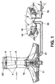
- a conventional cyclonic or anti-cyclonic conversion tower such as that represented in Figure 1, comprises a central vortical duct (1), at least one convector made up of two vertical membranes or screens (2) and (3), generated by a curve and limited on one of its sides by the central vortical duct (1), with at least two stiffeners per convector. It must be taken into account that in Figure 1 two stiffeners (4) and (5) are shown, which consist of a flat horizontal plate which extends between the membranes or screens (2) and (3), allowing it to be held and kept in position.
- blocking device (6) per convector, and a diffuser (23), a deflector (24), and means for converting kinetic energy into electrical energy, such as, for example, aero-turbines, contra-rotating or not, connected to generators (such as those which may be observed in Figure 9, to which reference will be made hereinbelow).
- the object of the blocking devices (6) is to allow the passage of fluid from the convectors to the central vortical duct (1), according to the orientation of the wind, while preventing on the other hand the passage of fluid from inside the central vortical duct to the convectors when the vortex has already been created.
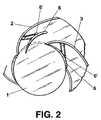
- Figure 2 represents a cross-section of a conventional cyclonic or anti-cyclonic conversion tower, in which one can see the central vortical duct (1), the membranes or screens (2) and (3), and also the blocking devices (6).
- the blocking devices (6) which have an aerodynamic shape to give the least resistance to the wind when they are in an open position, are attached to the membranes or screens (2) and (4) by damping arms (6') which are able to turn on their support by the simple action of the wind in order to allow the blocking devices (6) to open and close.
- the blocking device attached to the membrane or screen (2) is represented in an open position, while the one attached to the membrane or screen (3) is closed.
- the blocking device (6) corresponding to a converter in accordance with the present invention, may turn upon the guiding crown of the central vortical duct (1).
- the blocking devices (6) in accordance with the invention may be only two in number, to close only two convectors to leeward, up to a maximum of five, for a cyclonic or anti-cyclonic conversion tower with five convectors per level.
- the blocking devices (6) of the invention which may turn on the outer circumference of the central vortical duct (1) do so supported and anchored at the upper part and the lower part of the stiffeners in streamlined rails (7) and (8) provided with rolling elements.
- one, several or all the blocking devices (6) corresponding to this invention which can turn upon the outer circumference of the central vortical duct, do so under action of the flow by means of one or more retractable ailerons (9) in the servomotorised blocking device.
- the blocking devices (6) may be activated by the peripheral vortical flow itself, or by means of an appropriate conventional motorised mechanism (not shown).
- the blocking devices (6) of the invention may advantageously be provided with leeward stimulators (10) which allow the turning speed of the vortex to be increased.
- the leeward stimulators (10) consist of vertical slots which open as a result of the depression produced in the blocking devices (6) to leeward, and thereby a very thin layer of the potential vortex leaves the convector causing the rubbing of the vortical flow against the blocking devices (6) to be reduced to a minimum, and the consequent increase in the turning speed of the vortex.
- identical leeward stimulators (10) may be incorporated in the conventional blocking devices (6) with the same purpose.
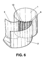
- the blocking devices (6) of the invention may be made up of a set of vertical slats (13), preferably with an aerodynamic shape, which may be activated by the convective flow itself or by motorised mechanisms fixed in the upper and lower part of the same.
- the leeward stimulators (10) are neither necessary nor useful, since the effect achieved with them on the conventional blocking devices (6) and on the blocking devices (6) in the form of a guiding crown of the present invention, is now obtained by leaving the vertical slats (13) slightly open.
- the inside of the cyclonic or anti-cyclonic conversion tower of the present invention has been advantageously provided with sensors (14) for appropriately controlling, regulating and positioning, by means of servo-mechanisms, one, several or all the blocking devices (6), whether the latter are in the form of a guiding crown or vertical slats (13).
- Sensors are also provided for the advanced detection of strength and direction of external wind flows, the sensors being situated radially at different heights and appropriate distances on the outside of the cyclonic or anti-cyclonic conversion tower, and allowing the blocking devices (6) to be appropriately positioned by means of suitable servo-mechanisms.
- the means for converting kinetic energy into electrical energy may be varied (including, without limitation, pumps, generators, compressors, dynamos and alternators), and as shown in Figure 9, they preferably include at least one aero-turbine (16), contra-rotating or not, provided with elements (16') for controlling its blades, the totally or partially opening or closing its diaphragmatic blocking device (26) and the exhaust of the same, as well as a generator (25) with a control element of the current frequency and its voltage.
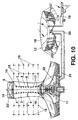
- a cyclonic or anti-cyclonic conversion tower of the invention may, as in the case of conventional cyclonic or anti-cyclonic conversion towers, be provided with a base in the form of a tank (11) of hot water and saturated air, which come from at least one pre-evaporator known as "hydric hothouse” (12).
- the hydric hothouse (12) is preferably provided with a thermally absorbent black bottom and in any case is covered by a transparent surface (18) and partly filled with water and partly with air gathered from the outside by means of the duct (19), elements which, under the heating effect caused by the action of the sun, generate air with humidity or saturated with water vapour, which is taken to the upper part of the bottom in the form of a tank (11) of the cyclonic or anti-cyclonic conversion tower by means of the duct (20).
- the base in the form of a tank (11) is partially filled in turn with water from the hydric hothouse (12) by means of the duct (20), thus creating in the lower part of the cyclonic or anti-cyclonic conversion tower of the present invention thermal conditions similar to those of a natural cyclone, which favour the creation of a vortex.
- each hydric hothouse (12) is provided with one or more sensors (22) which detect the air humidity level, allowing regulation of the degree of water vapour saturation of the air from the hydric hothouse (12), which penetrates into the cyclonic or anti-cyclonic conversion tower.
- the tower itself has a similar shape inside to a hollow cylindrical tower, provided with five curvilinear aerodynamic screens or convectors which collect, conduct and concentrate the laminar flow of the outside wind.
- the cyclonic tower (100) has a lower part (101) which is completely cylindrical, gradually increasing in diameter, that is, in a growing manner until it reaches an inverted trunco-conical shape (102) in its upper part, as shown in Figure 11.
- the cyclonic or anti-cyclonic conversion tower (100) is manufactured or constructed in reinforced concrete or another resistant material, with sliding or climbing shutters or by using prefabricated screens with post-stressing, which are separated by aerodynamic rings, sectors or “doughnuts", sections which are separated every two or six metres, in order to provide the structure with great rigidity, these elements being made, as in the case of the tower, of reinforced concrete or other resistant material.
- the static deflector-diffuser system is incorporated in order to prevent shearing of the confined cyclone and the deflector is situated in the lower part.
- Both the static diffuser system and the deflector may be made of pre-stressed concrete or autoxidizable steel.
- the invention is able to separate the collector of wind energy from the aeroturbine and in addition to collecting that energy, it is able to concentrate the wind flow.
- the contra-rotating aeroturbine and the electric generator are installed in the base of the tower (100) and in its axial axis or not. It must be indicated that when the humidity degree in the environment is not high, a hothouse is connected with water which collects solar radiation, heats the air and evaporates the water.
- the invention can be implemented with a servo-motor, logically to aid the moving of the blocking devices which act as opening and closing links to prevent the exit of the turbulent wind from inside the trunco-conical and cylindrical body or the vortical duct (100) to the outside.
- the key of the invention consists of the articulated final part (202) made of steel, of the convector (200) made of concrete; it must be indicated that when it reaches the blocking device (201), it retracts outwards to leave the way free for the blocking device.
- the part (202) remains at a tangent to the vortical duct, and thus this duct is completely trunco-conical or cylindrical, stopping the turbulent air.
Landscapes
- Engineering & Computer Science (AREA)
- Mechanical Engineering (AREA)
- Sustainable Development (AREA)
- Sustainable Energy (AREA)
- Chemical & Material Sciences (AREA)
- Combustion & Propulsion (AREA)
- General Engineering & Computer Science (AREA)
- Life Sciences & Earth Sciences (AREA)
- Power Engineering (AREA)
- Cyclones (AREA)
- Respiratory Apparatuses And Protective Means (AREA)
- Wind Motors (AREA)
- Organic Low-Molecular-Weight Compounds And Preparation Thereof (AREA)
- Devices And Processes Conducted In The Presence Of Fluids And Solid Particles (AREA)
- Polyesters Or Polycarbonates (AREA)
- Saccharide Compounds (AREA)
- Separating Particles In Gases By Inertia (AREA)
- Air-Flow Control Members (AREA)
- Automatic Tool Replacement In Machine Tools (AREA)
- Carbon And Carbon Compounds (AREA)
- Catalysts (AREA)
Abstract
Description
- The present specification refers to a cyclonic or anti-cyclonic conversion tower, whose purpose is to be used as a tower with the capacity for obtaining electrical energy from the same.
- The application of this invention is within the industry which manufactures apparatus, devices and elements for the transformation of energy from different origins into electrical energy.
- Cyclonic or anti-cyclonic conversion towers are systems which artificially reproduce confined turbulent flows, called vortices, which may be ascending or descending, from laminar wind flows. Inside the tower the different environmental energies can be integrated, that is kinetic wind energy, baric energy due to differences in atmospheric pressure at different levels of the atmosphere, convective thermal energy, and also thermal energy from condensation.
- Conventional cyclonic or anti-cyclonic towers are largely made up of a hollow central conduit, called a vortical duct from which, almost tangentially, two or more membranes, screens or vertical structures emerge, whose generatrices have a curved profile with an aerodynamic cross-section.
- Two of said membranes or screens, associated with the corresponding section of the central vortical duct, constitute a convector.
- As a general rule, there are usually five convectors per level, when they can be orientated in all directions. It must be pointed out that two of these membranes or screens of each convector are supported by means of stiffeners, which are horizontal plates with an aerodynamic cross-section.
- At the beginning of the convectors of the vortical duct, the blocking devices are placed, which allow the windward entry of the laminar outer flow but not the exit of flow from the vortical duct to the outside to leeward.
- In the upper part of the cyclonic converter there is the diffuser, which prevents the effect of shearing on the exit vortex caused by the flow of laminar air outside the tower, and in the lower part of the converter the deflector is situated, which prevents the depression created by the absorption of the vortical flow.
- Normally, at the base and at the upper part of the tower, the aero-turbines, contra-rotatory or not, are placed with the electrical generator, water pump, compressor or any element capable of generating energy, and optionally a hothouse may be added or devices for heating the air and evaporating water, with control of the thermal conditions, including a base in the form of a shallow pool of water in order to heat the air and attempt to saturate it with water vapour, either from the hothouse itself or from one or several hydric hothouses.
- A cyclonic or anti-cyclonic conversion tower with the features indicated above is disclosed in Spanish Invention Patent number 493,713.
- However, these cyclonic or anti-cyclonic conversion towers have a number of mechanical and cost drawbacks, arising to a great extent from the construction of conventional blocking devices.
- As may be observed in Spanish Invention Patent number 493,713, the blocking devices are movable screens with an aerodynamic profile which rest upon damping arms which turn around their support on one of the membranes or screens of the convector, in such a way that the blocking devices open when they are in a convector which must allow the passage of the exterior fluid or flow to the vortical duct, and close when the fluid or flow attempts to leave the central vortical duct outwards.
- A first problem consists of the reduction in the performance of the vortex, and even the destruction of the same due to the partial penetration of the blocking device into the vortical duct.
- Moreover, and secondly, the great stresses in the supporting points of the arms which hold the blocking devices, in the membranes or screens of the convectors and in the blocking devices themselves, involve a considerable difficulty for construction.
- Bear in mind, for example, that for a 100 Mw conversion tower, each blocking device would consist of screens of 70 m long by 3 m high, which holding and moving involve enormous stresses on the supporting points of the holding arms.
- This problem is further aggravated by the fact that sudden variations in wind speed or direction will increase the stresses, and as a result of these stresses, the shock absorbers and ball-and-socket joints of the holding arms and the blocking devices themselves undergo great wear, and in practice the materials and technology to make them at an acceptable cost are not known.
- Accordingly, the construction of these conversion towers requires special alloys of high rigidity but at the same time very light, which considerably increases the cost. of said conversion towers.
- Moreover, their maintenance is highly expensive and risky, requiring a large number of skilled personnel. At the same time, the high construction and maintenance costs as well as the limited performance caused by a vortex which is defective as a consequence of the partial introduction of the blocking devices in the central vortical duct, prevent the massive use of conversion towers for energy generation.
- The applicant is not aware that at the present time any element such as those mentioned above has been built.
- In a first embodiment, the cyclonic or anti-cyclonic conversion tower which is the object of the invention is comprised by a central vortical duct, at least one convector or several made up of two vertical membranes or screens, generated by a curve and which are limited at one of their sides by the central vortical duct, and at least two stiffeners per convector, a blocking device in the form of one guiding crown per convector, a diffuser, a deflector, and means for converting kinetic energy into electrical or mechanical energy. A blocking device can turn on the outer circumference of the central vortical duct, supported on the lower plane and anchored at the upper part of the stiffeners of the convectors.
- Preferably, one, several or all the blocking devices which can turn on the outer circumference of the central vortical duct, do so supported and anchored at the upper and lower part of the stiffeners on streamlined rails and with rolling or sliding elements.
- More preferably, one, several or all the blocking devices which can turn on the outer circumference of the central vortical duct, do so under the action of the peripheral vortical flow by means of one or more retractable ailerons on the blocking device and servomotorised, or by means of a motorised mechanism of the blocking device itself.
- Even more preferably, the number of blocking devices is two, three, four or five.
- Also, the invention envisages that one, several or all the blocking devices may or may not turn on the outer circumference of the central vortical duct, being provided with leeward stimulators consisting of vertical slots which open as a result of the depression produced in the blocking devices to leeward.
- Still more preferably, inside said cyclonic or anti-cyclonic conversion tower there are sensors for the appropriate controlling, regulating and positioning of one, several or all the blocking devices which can turn on the outer circumference of the central vortical duct, as well as sensors for the advanced detection of strength and direction of wind flows, situated radially at different heights and at symmetrical and appropriate distances on the outside of the cyclonic or anti-cyclonic conversion tower.
- Also preferably, the means for converting kinetic energy into electrical or mechanical energy consist of an aeroturbine, contra-rotatory or not, provided with control elements for its blades, for the total or partial opening or closing of its diaphragmatic blocking device and for the exhaust of the same, and also a generator.
- Preferably, likewise, there are elements of control and regulation of the flows of the vortex and, optionally, the first embodiment of the cyclonic or anti-cyclonic conversion tower of the present invention also comprises a base in the form of a tank of hot water and saturated air, as well as at least one hydric hothouse, outside the base, from which said hot water and said saturated air come, and more preferably, one or more sensors in each hydric hothouse which detect the humidity and air saturation degree.
- In a second embodiment, the cyclonic or anti-cyclonic conversion tower of the present invention comprises a central vortical duct, and at least one convector made up of two vertical membranes or screens, generated by a curve and which are limited at one of their sides by the central vortical duct, as well as at least two stiffeners per convector, one blocking device per convector which rests on damping arms which turn around their support on one of the membranes or screens of the convector, a diffuser, a deflector, and means for converting kinetic energy into electrical or mechanical energy. One, several or all of the blocking devices are provided with leeward stimulators which consist of vertical slots which open as a result of the depression produced in the blocking devices to leeward.
- The second embodiment of this invention corresponding to a cyclonic or anti-cyclonic conversion tower may have preferably two, three, four or five blocking devices at each level.
- In a third embodiment, the cyclonic or anti-cyclonic conversion tower of the present invention comprises a central vortical duct and at least one convector made up of two vertical membranes or screens, generated by a curve and are limited at one of their sides by the central vortical duct, having at least two stiffeners per convector, one blocking device per convector, a diffuser, a deflector, and means for converting kinetic energy into electrical or mechanical energy, in which at least one blocking device consists of several narrow and vertical slats situated all around the outer perimeter of the vortical duct, in relation to the corresponding convector.
- More preferably, in this third embodiment of the cyclonic or anti-cyclonic conversion tower of the -invention, one, several or all the vertical slats are aerodynamic.
- Even more preferably, in this third embodiment of the cyclonic or anti-cyclonic conversion tower of the invention, the vertical slats open under the action of the flow, or by means of motorised mechanisms fixed in the upper and/or lower part of the corresponding blocking device.
- Also preferably, the number of vertical slats of each blocking device in this third embodiment of the cyclonic or anti-cyclonic conversion tower of the invention depends on the strength of the tower and they are all around the perimeter of the outer vortical duct.
- In this third embodiment, the cyclonic or anti-cyclonic conversion tower may preferably have sensors inside the conversion tower for appropriately controlling, regulating and positioning one, several or all the vertical slats of the blocking devices corresponding to the convectors, as well as sensors for the advanced detection of the strength and direction of wind flows, situated radially and equidistant at different levels and appropriate distances on the outside of the conversion tower.
- Also preferably, in this third embodiment of the conversion tower of the invention, the means for converting electrical or mechanical energy consist of an aero-turbine, contra-rotatory or not, provided with elements for controlling its blades, the total or partial opening or closing of its diaphragmatic blocking device and the exhaust of the same, as well as one or several generators.
- Also preferably, there are control and regulation elements of the vortical flow.
- Optionally, the third embodiment of the cyclonic-anti-cyclonic conversion tower of the invention also comprises a base in the form of a shallow tank of hot water and saturated air, as well as at least one hydric hothouse, outside the base, from which said hot water and said saturated air come, and more preferably, one or more sensors in each hydric hothouse which detect the degree of humidity and saturation of the air with water vapour.
- In a fourth embodiment, the cyclonic or anti-cyclonic conversion tower is carried out on the basis of the construction of a tower made of reinforced concrete, provided with all the elements required for its operation, which has a hollow central area. At a determinate height, a gradual or growing increase begins in the diameter of the tower, which results in the configuration of a tower with a cylindrical lower area and an upper area similar to the trunk of an inverted cone.
- The invention also incorporates the relevant articulations on the convectors which in co-operation with the blocking devices of the area determined as a guiding crown, and the area corresponding to the inverted trunco-conical shape, are parts which are anchored to tracks perimetrically positioned on the body of the tower, acting as rails where these mobile parts are anchored, which are gradually opened and closed according to the effect of the wind and in accordance with the creation of the vortex.
- The articulation of these parts of the convectors, five of which act together, situated perimetrically, generates the expansion of the vortical duct and consequently multiplies the effectiveness of the invention.
- It must be specifically indicated that the blocking devices situated on the perimeter of the vortical duct which adopts the shape of a cylinder, logically have a curvature in accordance with the guiding crown, while those situated on the outer perimeter of the vortical duct in the area which adopts the inverted trunco-conical shape, will have a shape appropriate to carry out their function in a similar way to those situated in the cylindrical area, specifically adopting the surface shape of a split trunk-cone.
- It must be reiterated that the blocking devices which have the shape of a guiding crown and also those situated on the perimeter of the trunco-conical guiding crown, each have an angle of 72°, obtained as a result of dividing the 360° of a circle into five identical areas which close the perimeter.
- The invention is enhanced by wheels which are incorporated in the rails and consequently have a channelled shape, the steel tracks being fixed to the reinforced concrete and having inner reinforcements, both in the lower and in the upper part, and improved by a servomotor.
- To complement the description being given and in order to promote a fuller understanding of the features of the invention, a set of drawings accompanies the present specification as an integral part of the same, in which, illustratively and non-restrictively, the following is represented:
- Figure 1.- Corresponds to a diagrammatic view of a conventional cyclonic or anti-cyclonic conversion tower.
- Figure 2.- Shows a view in cross-section of a conventional cyclonic or anti-cyclonic conversion tower, similar to that represented in Figure 1, showing a conventional blocking device.
- Figure 3.- Is a perspective view of a cross-section of a conversion tower in accordance with the present invention, showing a blocking device in the form of a guiding crown.
- Figure 4.- Corresponds to perspective view of a cross-section of a tower in accordance with the invention, showing a blocking device in the form of a guiding crown with leeward stimulators.
- Figure 5.- Is a perspective view of a cross-section of a conventional conversion tower, similar to that represented in Figure 2, showing a similarly conventional blocking device provided with leeward stimulators.
- Figure 6.- Represents a perspective view of a cross-section of a conversion tower in accordance with the invention, showing a blocking device in the form of vertical slats.
- Figure 7.- Represents a perspective view of a conversion tower in accordance with the invention, incorporating sensors on the outside of the conversion tower itself.
- Figure 8.- Shows an upper view of a conversion tower in accordance with the present invention and of its surroundings, showing the placing of the external sensors.
- Figure 9.- Represents a perspective view of an aero-turbine, contra-rotating or not, which can be used in a conversion tower in accordance with the present invention, showing the elements which control its blades, the total or partial opening or closing of its diaphragmatic blocking device and the exhaust of the same.
- Figure 10.- Corresponds to a diagrammatic view of a conversion tower in accordance with the invention, showing the control and regulation systems of the vortical flows, a hydric hothouse, as well as the sensors of the humidity and air saturation degree.
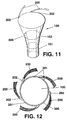
- Figure 11.- Represents a possible embodiment of the invention, with the tower adopting a trunco-conical shape in the upper part and the cylindrical shape in the lower part.
- Figure 12.- Represents a plan view of the object shown in Figure 11, provided with the necessary elements.
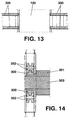
- Figure 13.- Corresponds to a front elevation view duly cross-sectioned of the inner fixing areas of the auxiliary elements.
- Figure 14. Finally shows a detail of the means whereby the internal mobile elements are fixed to the rails.
-
- A conventional cyclonic or anti-cyclonic conversion tower, such as that represented in Figure 1, comprises a central vortical duct (1), at least one convector made up of two vertical membranes or screens (2) and (3), generated by a curve and limited on one of its sides by the central vortical duct (1), with at least two stiffeners per convector. It must be taken into account that in Figure 1 two stiffeners (4) and (5) are shown, which consist of a flat horizontal plate which extends between the membranes or screens (2) and (3), allowing it to be held and kept in position. There is also one blocking device (6) per convector, and a diffuser (23), a deflector (24), and means for converting kinetic energy into electrical energy, such as, for example, aero-turbines, contra-rotating or not, connected to generators (such as those which may be observed in Figure 9, to which reference will be made hereinbelow).
- A construction of this type may be seen in Spanish Patent of Invention number 493,713, which is incorporated in the present specification by way of reference.
- The object of the blocking devices (6) is to allow the passage of fluid from the convectors to the central vortical duct (1), according to the orientation of the wind, while preventing on the other hand the passage of fluid from inside the central vortical duct to the convectors when the vortex has already been created.
- Figure 2 represents a cross-section of a conventional cyclonic or anti-cyclonic conversion tower, in which one can see the central vortical duct (1), the membranes or screens (2) and (3), and also the blocking devices (6).
- As may be observed, the blocking devices (6), which have an aerodynamic shape to give the least resistance to the wind when they are in an open position, are attached to the membranes or screens (2) and (4) by damping arms (6') which are able to turn on their support by the simple action of the wind in order to allow the blocking devices (6) to open and close.
- In Figure 2, the blocking device attached to the membrane or screen (2) is represented in an open position, while the one attached to the membrane or screen (3) is closed.
- With reference to Figure 3, it may be observed that the blocking device (6) corresponding to a converter in accordance with the present invention, may turn upon the guiding crown of the central vortical duct (1).
- This occurs thanks to the configuration of the blocking device (6) in the shape of a guiding crown, which has the same diameter as the circumference of the outside of the central vortical duct (1) corresponding to the specific convector in question.
- The blocking devices (6) in accordance with the invention may be only two in number, to close only two convectors to leeward, up to a maximum of five, for a cyclonic or anti-cyclonic conversion tower with five convectors per level.
- Although less advantageously, several blocking devices (6) corresponding to the present invention may be combined, represented graphically in Figure 3 with several conventional blocking devices (6) represented in Figure 2.
- Preferably, and also with reference to Figure 3, the blocking devices (6) of the invention which may turn on the outer circumference of the central vortical duct (1) do so supported and anchored at the upper part and the lower part of the stiffeners in streamlined rails (7) and (8) provided with rolling elements.
- Also preferably, one, several or all the blocking devices (6) corresponding to this invention which can turn upon the outer circumference of the central vortical duct, do so under action of the flow by means of one or more retractable ailerons (9) in the servomotorised blocking device. The blocking devices (6) may be activated by the peripheral vortical flow itself, or by means of an appropriate conventional motorised mechanism (not shown).
- As may be observed in Figure 4, the blocking devices (6) of the invention may advantageously be provided with leeward stimulators (10) which allow the turning speed of the vortex to be increased.
- The leeward stimulators (10) consist of vertical slots which open as a result of the depression produced in the blocking devices (6) to leeward, and thereby a very thin layer of the potential vortex leaves the convector causing the rubbing of the vortical flow against the blocking devices (6) to be reduced to a minimum, and the consequent increase in the turning speed of the vortex.
- In fact, and as represented in Figure 5, identical leeward stimulators (10) may be incorporated in the conventional blocking devices (6) with the same purpose.
- Alternatively, and as may be seen in Figure 6, the blocking devices (6) of the invention may be made up of a set of vertical slats (13), preferably with an aerodynamic shape, which may be activated by the convective flow itself or by motorised mechanisms fixed in the upper and lower part of the same.
- In this embodiment the leeward stimulators (10) are neither necessary nor useful, since the effect achieved with them on the conventional blocking devices (6) and on the blocking devices (6) in the form of a guiding crown of the present invention, is now obtained by leaving the vertical slats (13) slightly open.
- With reference to Figures 7 and 8, the inside of the cyclonic or anti-cyclonic conversion tower of the present invention has been advantageously provided with sensors (14) for appropriately controlling, regulating and positioning, by means of servo-mechanisms, one, several or all the blocking devices (6), whether the latter are in the form of a guiding crown or vertical slats (13).
- Sensors (15) are also provided for the advanced detection of strength and direction of external wind flows, the sensors being situated radially at different heights and appropriate distances on the outside of the cyclonic or anti-cyclonic conversion tower, and allowing the blocking devices (6) to be appropriately positioned by means of suitable servo-mechanisms.
- As in conventional cyclonic or anti-cyclonic conversion towers, in a cyclonic or anti-cyclonic conversion tower in accordance with the present invention, the means for converting kinetic energy into electrical energy may be varied (including, without limitation, pumps, generators, compressors, dynamos and alternators), and as shown in Figure 9, they preferably include at least one aero-turbine (16), contra-rotating or not, provided with elements (16') for controlling its blades, the totally or partially opening or closing its diaphragmatic blocking device (26) and the exhaust of the same, as well as a generator (25) with a control element of the current frequency and its voltage.
- Preferably, likewise, in the cyclonic or anti-cyclonic conversion towers of the present invention there are elements for controlling and regulating (17) the flows of the vortex, as may be observed in Figure 10.
- Optionally, and as may also be seen in Figure 10, a cyclonic or anti-cyclonic conversion tower of the invention may, as in the case of conventional cyclonic or anti-cyclonic conversion towers, be provided with a base in the form of a tank (11) of hot water and saturated air, which come from at least one pre-evaporator known as "hydric hothouse" (12).
- The hydric hothouse (12) is preferably provided with a thermally absorbent black bottom and in any case is covered by a transparent surface (18) and partly filled with water and partly with air gathered from the outside by means of the duct (19), elements which, under the heating effect caused by the action of the sun, generate air with humidity or saturated with water vapour, which is taken to the upper part of the bottom in the form of a tank (11) of the cyclonic or anti-cyclonic conversion tower by means of the duct (20).
- The base in the form of a tank (11) is partially filled in turn with water from the hydric hothouse (12) by means of the duct (20), thus creating in the lower part of the cyclonic or anti-cyclonic conversion tower of the present invention thermal conditions similar to those of a natural cyclone, which favour the creation of a vortex.
- Preferably, each hydric hothouse (12) is provided with one or more sensors (22) which detect the air humidity level, allowing regulation of the degree of water vapour saturation of the air from the hydric hothouse (12), which penetrates into the cyclonic or anti-cyclonic conversion tower.
- In another embodiment of the invention, configured as a collector-concentrator system, the tower itself has a similar shape inside to a hollow cylindrical tower, provided with five curvilinear aerodynamic screens or convectors which collect, conduct and concentrate the laminar flow of the outside wind. It must be pointed out that the cyclonic tower (100) has a lower part (101) which is completely cylindrical, gradually increasing in diameter, that is, in a growing manner until it reaches an inverted trunco-conical shape (102) in its upper part, as shown in Figure 11.
- The cyclonic or anti-cyclonic conversion tower (100) is manufactured or constructed in reinforced concrete or another resistant material, with sliding or climbing shutters or by using prefabricated screens with post-stressing, which are separated by aerodynamic rings, sectors or "doughnuts", sections which are separated every two or six metres, in order to provide the structure with great rigidity, these elements being made, as in the case of the tower, of reinforced concrete or other resistant material.
- In the upper part of the tower (100) the static deflector-diffuser system is incorporated in order to prevent shearing of the confined cyclone and the deflector is situated in the lower part. Both the static diffuser system and the deflector may be made of pre-stressed concrete or autoxidizable steel.
- The invention is able to separate the collector of wind energy from the aeroturbine and in addition to collecting that energy, it is able to concentrate the wind flow.
- In the base of the tower (100) and in its axial axis or not, the contra-rotating aeroturbine and the electric generator are installed. It must be indicated that when the humidity degree in the environment is not high, a hothouse is connected with water which collects solar radiation, heats the air and evaporates the water.
- Continuing with Figure 12, it may be observed that on the inner perimeter of the tower (100) or vortical duct there are articulated parts (202) in the final part of the convector (200), which are five in number and surround both the cylindrical area and the trunco-conical area, two of said parts (202) turning inwards when the blocking devices (201) are in that position according to the wind direction; moreover, three of said articulations maintain a tangential position with respect to the vortical duct, being fixed by means of the relevant high-resistance articulations (202) to the upper and lower sectors or "doughnuts".
- To these upper and lower sectors or "doughnuts" (303) the rails or tracks (300) are fixed, along which channelled wheels (302) of the blocking devices (301) travel.
- The invention can be implemented with a servo-motor, logically to aid the moving of the blocking devices which act as opening and closing links to prevent the exit of the turbulent wind from inside the trunco-conical and cylindrical body or the vortical duct (100) to the outside.
- The key of the invention consists of the articulated final part (202) made of steel, of the convector (200) made of concrete; it must be indicated that when it reaches the blocking device (201), it retracts outwards to leave the way free for the blocking device.
- When the blocking device is not there, the part (202) remains at a tangent to the vortical duct, and thus this duct is completely trunco-conical or cylindrical, stopping the turbulent air.
- Finally, it must be pointed out that the parts which surround the inverted trunco-conical configuration have a split trunco-conical surface and the number of parts which surround the area is five.
Claims (28)
- A cyclonic or anti-cyclonic conversion tower, comprising:a.- a central vortical conduit (1);b.- at least one convector made up of two vertical membranes or screens (2) and (3), generated by a curve and limited on one of their sides by the central vortical duct (1);c.- at least two stiffeners (4) and (5) per convector;d.- one blocking device (6) per convector, two per convector or more;e.- a diffuser (23);f.- a deflector (24); andg.- means (16) and (25) for converting kinetic wind energy, baric position energy and convective energy, as well as thermal condensation energy into electrical or mechanical energy, characterised in that:At least one blocking device (6) can turn on the outer guiding crown of the central vortical duct (1).
- A cyclonic or anti-cyclonic conversion tower in accordance with claim 1, further characterised in that one, several or all the blocking devices in the form of a guiding crown (6) which can turn on the outer guiding crown of the central vortical duct (1) do so supported and anchored in the upper and lower part of the stiffeners on circular streamlined rails (7) and (8) and the blocking devices with rolling elements.
- A cyclonic or anti-cyclonic conversion tower in accordance with any of the foregoing claims, characterised in that also one, several or all the blocking devices in the form of a guiding crown (6) which can turn on the outer circumference of the central vortical duct (1) do so under the action of the flow by means of one or more retractable ailerons (9) in the servo-motorised blocking device.
- A cyclonic or anti- cyclonic conversion tower in accordance with claim 1 and 2, characterised in that one, several or all of the blocking devices (6) in the form of guiding crowns which can turn on the outer circumference of the central vortical duct (1) do so by means of a motorised mechanism.
- A cyclonic or anti-cyclonic conversion tower in accordance with the foregoing claims, characterised in that the number of blocking devices (6) is two, three, four or five.
- A cyclonic or anti-cyclonic conversion tower in accordance with the foregoing claims, characterised in that one, several or all the blocking devices (6) may or may not turn on the outer circumference of the central vortical duct (1), being provided with leeward stimulators (10) consisting of vertical slots which open as a result of the depression produced in the blocking devices (6) to leeward.
- A cyclonic or anti-cyclonic conversion tower in accordance with the foregoing claims, characterised in that inside said cyclonic or anti-cyclonic conversion tower, it is provided with sensors (14) for appropriately controlling, regulating and positioning one, several or all the blocking devices (6) which can turn on the outer circumference of the central vortical duct (1).
- A cyclonic or anti-cyclonic conversion tower in accordance with the foregoing claims, characterised in that outside said cyclonic or anti-cyclonic conversion tower, there are sensors (15) for the advanced detection of the strength and direction of wind flows, radially situated at different heights and at adequate distances.
- A cyclonic or anti-cyclonic conversion tower in accordance with the foregoing claims, characterised in that the means for converting kinetic energy into electrical energy consist of an aero-turbine (16), contra-rotating or not, provided with elements (16') for controlling its blades, the total or partial opening or closing of its diaphragmatic blocking device and the exhaust of the same, as well as a generator.
- A cyclonic or anti-cyclonic conversion tower in accordance with the foregoing claims, characterised in that it is provided with elements (17) for controlling and regulating the flows of the vortex.
- A cyclonic or anti-cyclonic conversion tower in accordance the foregoing claims, characterised in that it comprises a base in the form of a shallow tank (11) of hot water and saturated air, as well as at least one hydric hothouse (12) outside the base, from which said hot water and said saturated air come.
- A cyclonic or anti-cyclonic conversion tower in accordance with claim 11, characterised in that it further comprises in each hydric hothouse (12) one or more sensors (22) which detect the degree of humidity and water vapour saturation of the air.
- A cyclonic or anti-cyclonic conversion tower, comprising:a.- a central vortical duct (1);b.- at least one convector made up of two vertical membranes or screens (2) and (3), generated by a curve and limited on one of their sides by the central vortical duct (1);c.- at least two stiffeners (4) and (5) per convector;d.- one blocking device (6) per convector, which rests on damping arms which turn around their support on one of the membranes or screens (2) and (3) of the convector;e.- a diffuser (23);f.- a deflector (24); andg.- means (16) and (25) for converting kinetic energy into electrical or mechanical energy, characterised in that one, several or all of the blocking devices (6) are provided with leeward stimulators (10), consisting of vertical slots which open as a result of the depression produced in the blocking devices (6) to leeward.
- A cyclonic or anti- cyclonic conversion tower in accordance with claim 13, characterised in that the number of blocking devices (6) is two, three, four or five.
- A cyclonic or anti-cyclonic conversion tower, comprising:a.- a central vortical duct (1);b.- at least one convector made up of two vertical membranes or screens (2) and (3), generated by a curve and limited on one of their sides by the central vortical duct (1);c.- at least two stiffeners (4) and (5) per convector;d.- one blocking device (6) per convector;e.- a diffuser (23);f.- a deflector (24); andg.- means (16) and (25) for converting kinetic energy into electrical or mechanical energy, characterised in that at least one blocking device (6) consists of several vertical slats (13) situated in the outer perimeter of the vortical duct (1), relative to the corresponding convector.
- A cyclonic or anti-cyclonic conversion tower in accordance with claim 15, characterised in that one, several or all the vertical slats (13) are aerodynamic.
- A cyclonic or anti-cyclonic conversion tower in accordance with claims 15 and 16, characterised in that the vertical slats (13) open under the action of the flow.
- A cyclonic or anti-cyclonic conversion tower in accordance with claims 16 and 17, characterised in that the vertical slats (13) open by means of motorised mechanisms, fixed in the upper and lower part of the corresponding convector (6).
- A cyclonic or anti-cyclonic conversion tower in accordance with any of the claims 16 to 18, characterised in that the slats of the blocking devices are in the entire outer perimeter of the central vortex of all the convectors.
- A cyclonic or anti-cyclonic conversion tower in accordance with any of the claims 16 to 19, characterised in that inside said cyclonic or anti-cyclonic conversion tower, sensors (14) are situated for appropriately controlling, regulating and positioning one, several or all the blocking devices (6) which consist of vertical slats (13).
- A cyclonic or anti-cyclonic conversion tower in accordance with claims 16 to 20, characterised in that outside said cyclonic or anti-cyclonic conversion tower, there are sensors (15) for the advanced detection of the strength and direction of wind flows, radially situated at different heights and at adequate and symmetrical distances from the axis of the tower.
- A cyclonic or anti-cyclonic conversion tower in accordance with any of the claims 16 to 21, characterised in that the means for converting kinetic energy into electrical energy consist of an aero-turbine (16), contra-rotating or not, provided with elements (16') for controlling its blades, the total or partial opening or closing of its diaphragmatic blocking device and the exhaust of the same, as well as a generator (25) with electronic elements for regulating the frequency and voltage.
- A cyclonic or anti-cyclonic conversion tower in accordance with claims 16 to 22, characterised in that it is provided with elements (17) for controlling and regulating the flows of the vortex.
- A cyclonic or anti-cyclonic conversion tower in accordance with claims 16 to 23, characterised in that it is provided with a base in the form of a shallow tank (11) of hot water and saturated air, as well as at least one hydric hothouse (12) outside the base, from which said hot water and said saturated air come.
- A cyclonic or anti-cyclonic conversion tower in accordance with claim 24, characterised in that in each hydrid hothouse (12) it further comprises one or more sensors (22), which detect the degree of humidity and water vapour saturation of the air.
- A cyclonic or anti-cyclonic conversion tower in accordance with the foregoing claims, of the type made up of a static collector-concentrator system, a static diffuser-deflector system, an electric aeroturbine-generator system, and a hothouse system, and of the type configured as a cylindrical tower, hollow inside, provided with five curvilinear aerodynamic screens which collect, conduct and concentrate the laminar flow of the outer wind, being built of reinforced concrete with sliding or climbing shutters, or with prefabricated, post-stressed screens, separated by aerodynamic rings, sectors or "doughnuts", which make the structure rigid and which are made of reinforced concrete, there being in the upper part of the tower a diffuser which prevents shearing of the confined cyclone and in the lower part a deflector, characterised in that the body of the tower (100) adopts a cylindrical shape in its lower part, while in its upper part it has an inverted trunco-conical shape, deriving from the gradual growth of the diameter of the cylindrical area (101), until it reaches the inverted trunco-conical shape (102) in the upper part. The diffuser, in the upper part and the deflector in the lower part are made of reinforced or pre-stressed concrete or autoxidizable steel, having the possibility of separating the collector of wind energy from the aeroturbine, concentrating the wind flow and having, at the base of the tower (100) and in its axial axis or not, a contra-rotating aeroturbine and the electric generator. Also, a hothouse with water can be connected to the lower part, and, in the perimeter of the tower, in its cylindrical area and in its trunco-conical area, there are five screens (200) with a curvilinear shape in accordance with the outer perimeter of the tower, which have a curvature of 72°.
- A cyclonic or anti-cyclonic conversion tower in accordance claim 26, characterised in that the final part (202) of the convector (200) is articulated (202).
- A cyclonic or anti- cyclonic conversion tower in accordance with claims 26 and 27, characterised in that the two closing devices per section in the trunco-conical area have a shape that conforms with the structure, specifically, the inverted trunco-conical surface shape.
Applications Claiming Priority (3)
| Application Number | Priority Date | Filing Date | Title |
|---|---|---|---|
| ES9901093 | 1999-04-29 | ||
| ES009901093A ES2166663B1 (en) | 1999-05-20 | 1999-05-20 | TOWER OF CICLONIC OR ANTICICLONIC CONVERSION. |
| PCT/ES2000/000184 WO2000071893A1 (en) | 1999-05-20 | 2000-05-19 | Cyclonic or anti-cyclonic conversion tower |
Publications (2)
| Publication Number | Publication Date |
|---|---|
| EP1180597A1 true EP1180597A1 (en) | 2002-02-20 |
| EP1180597B1 EP1180597B1 (en) | 2004-04-14 |
Family
ID=8308496
Family Applications (1)
| Application Number | Title | Priority Date | Filing Date |
|---|---|---|---|
| EP00927258A Expired - Lifetime EP1180597B1 (en) | 1999-05-20 | 2000-05-19 | Cyclonic or anti-cyclonic conversion tower |
Country Status (13)
| Country | Link |
|---|---|
| US (1) | US6590300B1 (en) |
| EP (1) | EP1180597B1 (en) |
| AT (1) | ATE264455T1 (en) |
| AU (1) | AU768193B2 (en) |
| BR (1) | BR0011594B1 (en) |
| CA (1) | CA2374584C (en) |
| DE (1) | DE60009895T2 (en) |
| DK (1) | DK1180597T3 (en) |
| ES (1) | ES2166663B1 (en) |
| MA (1) | MA25360A1 (en) |
| MX (1) | MXPA01011827A (en) |
| PT (1) | PT1180597E (en) |
| WO (1) | WO2000071893A1 (en) |
Cited By (7)
| Publication number | Priority date | Publication date | Assignee | Title |
|---|---|---|---|---|
| RU2246031C1 (en) * | 2003-05-26 | 2005-02-10 | Каравацкий Эдуард Станиславович | Wind-power station (versions) |
| ITRM20080420A1 (en) * | 2008-08-01 | 2010-02-02 | Livio Biagini | PERFECT WIND SILOS. |
| RU2387871C1 (en) * | 2008-11-12 | 2010-04-27 | Общество с ограниченной ответственностью "Иркутский научно-исследовательский институт лесной промышленности | Windmill |
| WO2011011109A1 (en) * | 2009-07-20 | 2011-01-27 | Windpipe Corporation | Method and system of extracting energy from wind |
| FR2964420A1 (en) * | 2010-09-03 | 2012-03-09 | IFP Energies Nouvelles | Wind driven device for use on roof of building to produce heat energy, cold energy or water, has main turbomachine element comprising turbines for capturing wind energy, where each turbine's axis is parallel to axis of air inlet element |
| FR3001254A1 (en) * | 2013-01-18 | 2014-07-25 | Chuen-Yu John Chan | INSTALLATION AND METHOD FOR PRODUCING MECHANICAL OR ELECTRICAL ENERGY FROM A FLUID AT TEMPERATURE EXCEEDING THE AMBIENT TEMPERATURE |
| WO2015185765A1 (en) * | 2014-06-03 | 2015-12-10 | Centrales Energéticas Ciclónicas, S. L | A cyclonic wind energy converter |
Families Citing this family (57)
| Publication number | Priority date | Publication date | Assignee | Title |
|---|---|---|---|---|
| EP1290342A1 (en) * | 2000-06-14 | 2003-03-12 | Ernest R. Drucker | Solar chimney wind turbine |
| US6717285B2 (en) * | 2000-09-28 | 2004-04-06 | Michael Ferraro | Multiple collector wind driven power generating device |
| US7154190B2 (en) * | 2002-04-29 | 2006-12-26 | Solomon Kaploun | All-weather energy and water production via steam-enhanced vortex tower |
| US6943461B2 (en) * | 2002-04-29 | 2005-09-13 | Solomon Kaploun | All-weather energy and water production via steam-enhanced vortex tower |
| AU2002951017A0 (en) * | 2002-08-26 | 2002-09-12 | Jott Australia Pty Ltd | Performance augmentation of natural draft cooling towers |
| WO2004083628A1 (en) * | 2003-03-21 | 2004-09-30 | Nikolaus Vida | Tornado-type wind or water turbine |
| US20040250543A1 (en) * | 2003-06-11 | 2004-12-16 | Chao-Chin Yeh | Solar power generating apparatus |
| US7511387B2 (en) * | 2003-10-04 | 2009-03-31 | Mehdi Fakhrai | Method and apparatus for producing energy using air pressure differential |
| ES2234434B1 (en) * | 2003-12-03 | 2006-11-01 | Universitat Politecnica De Catalunya. | SUPERCONDUCTOR SUBSTANCE AEROGENERATOR. |
| UA76279C2 (en) * | 2004-07-15 | 2006-07-17 | Stanislav Ivanovych Husak | Method for transfer of accumulated heat power in wind power unit and wind power unit with energy accumulation |
| KR101383849B1 (en) * | 2004-12-23 | 2014-04-10 | 카트루 에코-에너지 그룹 피티이. 엘티디. | Omni-directional wind turbine |
| US7112893B1 (en) * | 2005-03-16 | 2006-09-26 | Villanueva Alvin P | Power generating wind turbine |
| US20070035138A1 (en) * | 2005-07-18 | 2007-02-15 | Khan Sajid A | Vacuum powered generators |
| WO2007022556A1 (en) * | 2005-08-22 | 2007-03-01 | Louat, Heather | Improvements to solar heat engines and industrial chimneys |
| US8403623B2 (en) * | 2005-12-29 | 2013-03-26 | Brett C. Krippene | Wind energy power enhancer system |
| US9273665B1 (en) | 2005-12-29 | 2016-03-01 | Brett C. Krippene | Dual wind energy power enhancer system |
| FR2903740B1 (en) * | 2006-07-17 | 2009-02-20 | Marc Raynal | DEVICE FOR PRODUCING MECHANICAL ENERGY USING A TELESCOPIC DIVERGENT CHIMNEY AND SELF-SUSTAINED. |
| US7918650B2 (en) | 2007-01-26 | 2011-04-05 | Eugene Papp | System for pressurizing fluid |
| UA85286C2 (en) * | 2007-04-10 | 2009-01-12 | Станислав Иванович Гусак | Method of operation of wind-power system and wind-power system |
| RU2339842C1 (en) * | 2007-04-16 | 2008-11-27 | Станислав Иванович Гусак | Method of wind-driven system operation and wind-driven system |
| US20080315593A1 (en) * | 2007-06-25 | 2008-12-25 | Paul Ducharme | Wind dam |
| US8047804B2 (en) * | 2007-12-27 | 2011-11-01 | General Electric Company | Wind tower and method of assembling the same |
| US7821151B2 (en) * | 2008-02-23 | 2010-10-26 | Le John O | Hybrid solar thermal chimney |
| EP2108820A2 (en) * | 2008-04-09 | 2009-10-14 | Proyectos de ingenieria tecnologica, S.A. | Wind turbine |
| TWM349433U (en) * | 2008-07-25 | 2009-01-21 | Jetpo Technology Inc | Solar electricity generating device |
| US20100060010A1 (en) * | 2008-09-10 | 2010-03-11 | Iosif Gaportsin | Ecology friendly compound energy unit |
| RU2395003C2 (en) * | 2008-10-01 | 2010-07-20 | Владимир Владимирович Крохалев | Method and device for generation of electric energy on renewable energy sources |
| RU2386853C1 (en) * | 2009-02-09 | 2010-04-20 | Сергей Иванович Коломацкий | Vortex wind plant |
| GB0906111D0 (en) * | 2009-04-08 | 2009-05-20 | Current 2 Current Ltd | Generation apparatus |
| ES2370552B1 (en) * | 2009-06-19 | 2013-02-15 | Abengoa Solar New Technologies, S.A. | NATURAL SHOT COOLING PROCEDURE OF A SOLAR CONCENTRATION PLANT. |
| US8534068B2 (en) * | 2010-01-15 | 2013-09-17 | Pitaya Yangpichit | Solar chimney with wind turbine |
| US8338977B2 (en) * | 2010-03-04 | 2012-12-25 | William Edward Lee | Hybrid vertical axis energy apparatus |
| DE102010024621B4 (en) * | 2010-03-08 | 2016-06-30 | Gebhard Bernsau | energy converters |
| US8928169B2 (en) * | 2010-09-09 | 2015-01-06 | The Aerospace Corporation | Energy generation apparatus and method |
| US8461715B2 (en) * | 2010-10-10 | 2013-06-11 | Hong Kong Applied Science and Technology Research Institute Company Limited | Apparatus for wind collection |
| US8552580B2 (en) * | 2010-11-26 | 2013-10-08 | Justin Dale Tackett | Wind turbine power generation |
| WO2013100865A1 (en) | 2011-12-30 | 2013-07-04 | Pitaya Yangpichit | Solar chimney with external vertical axis wind turbine |
| US9062896B2 (en) | 2013-05-16 | 2015-06-23 | Martin Eugene Nix | System to create rotational energy from a wind-chimmey and solar-smelter |
| US20140375057A1 (en) * | 2013-06-23 | 2014-12-25 | Gaurav BAZAZ | Artificial wind generator |
| US20140284928A1 (en) * | 2014-04-22 | 2014-09-25 | Research Energy Llc. | Harnessing electricity from controlled tornado |
| CN103994025B (en) * | 2014-05-22 | 2016-12-07 | 衢州昀睿工业设计有限公司 | A kind of airduct TRT |
| US10060410B2 (en) * | 2015-08-21 | 2018-08-28 | Dongho Kim | Gravity power and desalination technology system |
| US20160186725A1 (en) * | 2016-03-04 | 2016-06-30 | Nestor Dofredo | Thermal wind turbines |
| CA3065354A1 (en) | 2016-07-06 | 2018-01-11 | Auckland Uniservices Limited | Vortex station |
| US12071936B2 (en) | 2017-07-06 | 2024-08-27 | Auckland Uniservices Limited | Vortex station |
| CN106823715B (en) * | 2017-03-03 | 2023-10-20 | 北京朗净时代环境科技有限公司 | Double-cyclone desulfurization synergistic device and multistage double-cyclone desulfurization synergistic device |
| US9850883B1 (en) * | 2017-08-10 | 2017-12-26 | Bajaura S.A. DE C.V. | Apparatus and method for generating electricity from integrated air flows and thermal energy |
| US10337504B1 (en) | 2017-12-15 | 2019-07-02 | King Fahd University Of Petroleum And Minerals | Solar chimney for power production using fresnel lens |
| CA2997766C (en) * | 2018-03-08 | 2019-10-08 | Branko Mizerit | Vortex acceleration wind energy tower |
| US10947957B1 (en) * | 2018-11-29 | 2021-03-16 | Keith G. Bandy | Apparatus, system and method for utilizing kinetic energy to generate electricity |
| RU195338U1 (en) * | 2019-02-15 | 2020-01-23 | Общество С Ограниченной Ответственностью Малое Инновационное Предприятие "Экономика Энергетика Экология" | HYBRID WIND POWER COMPLEX |
| RU2714023C1 (en) * | 2019-06-10 | 2020-02-11 | Игорь Александрович Щукин | Wind-driven power plant |
| US10876519B1 (en) * | 2019-11-06 | 2020-12-29 | Thomas Chaapel | Power generating device |
| EP4080040B1 (en) * | 2019-12-16 | 2026-04-22 | TOO "PS Consulting" (KZ) | Vertical-axis wind turbine |
| WO2023095158A1 (en) * | 2021-11-26 | 2023-06-01 | Jambu Nathan Vishak | Diffuser augmented wind turbine with blockage mechanism and method thereof |
| JP7809556B2 (en) * | 2022-03-16 | 2026-02-02 | 株式会社フジタ | power generation equipment |
| US20250179996A1 (en) * | 2023-11-30 | 2025-06-05 | Chio-Sung Chang | Tower base automatic ventilation system for thermal convective wind power generation device |
Family Cites Families (12)
| Publication number | Priority date | Publication date | Assignee | Title |
|---|---|---|---|---|
| US3788385A (en) * | 1970-11-23 | 1974-01-29 | Chicago Bridge & Iron Co | Dry type, liquid-solid cooling system |
| US3936652A (en) * | 1974-03-18 | 1976-02-03 | Levine Steven K | Power system |
| US4070131A (en) * | 1975-01-20 | 1978-01-24 | Grumman Aerospace Corporation | Tornado-type wind turbine |
| US4031173A (en) * | 1976-03-25 | 1977-06-21 | Paul Rogers | Efficiency and utilization of cooling towers |
| ES8301330A1 (en) * | 1980-07-24 | 1982-12-01 | Central Energetic Ciclonic | System for the obtaining of energy by fluid flows resembling a natural cyclone or anti-cyclone |
| US4433544A (en) * | 1982-05-19 | 1984-02-28 | The United States Of America As Represented By The Administrator Of The National Aeronautics And Space Administration | Wind and solar powered turbine |
| US4508973A (en) * | 1984-05-25 | 1985-04-02 | Payne James M | Wind turbine electric generator |
| US4945693A (en) * | 1989-03-10 | 1990-08-07 | Cooley Warren L | Concentric dome energy generating building enclosure |
| US5300817A (en) * | 1993-04-16 | 1994-04-05 | Baird William R | Solar venturi turbine |
| FI952623A7 (en) * | 1995-05-30 | 1996-12-01 | Laempoetaito Oy | Method and apparatus for increasing wind power density and recovering wind energy |
| US6510687B1 (en) * | 1996-06-14 | 2003-01-28 | Sharav Sluices Ltd. | Renewable resource hydro/aero-power generation plant and method of generating hydro/aero-power |
| US6215199B1 (en) * | 1999-11-13 | 2001-04-10 | Adolf Lysenko | Wind-driven electrical energy generating device |
-
1999
- 1999-05-20 ES ES009901093A patent/ES2166663B1/en not_active Expired - Lifetime
-
2000
- 2000-05-19 US US09/979,604 patent/US6590300B1/en not_active Expired - Lifetime
- 2000-05-19 AU AU56457/00A patent/AU768193B2/en not_active Ceased
- 2000-05-19 CA CA002374584A patent/CA2374584C/en not_active Expired - Lifetime
- 2000-05-19 EP EP00927258A patent/EP1180597B1/en not_active Expired - Lifetime
- 2000-05-19 AT AT00927258T patent/ATE264455T1/en active
- 2000-05-19 MX MXPA01011827A patent/MXPA01011827A/en active IP Right Grant
- 2000-05-19 WO PCT/ES2000/000184 patent/WO2000071893A1/en not_active Ceased
- 2000-05-19 BR BRPI0011594-0A patent/BR0011594B1/en not_active IP Right Cessation
- 2000-05-19 DK DK00927258T patent/DK1180597T3/en active
- 2000-05-19 DE DE60009895T patent/DE60009895T2/en not_active Expired - Lifetime
- 2000-05-19 PT PT00927258T patent/PT1180597E/en unknown
-
2001
- 2001-11-16 MA MA26414A patent/MA25360A1/en unknown
Non-Patent Citations (1)
| Title |
|---|
| See references of WO0071893A1 * |
Cited By (10)
| Publication number | Priority date | Publication date | Assignee | Title |
|---|---|---|---|---|
| RU2246031C1 (en) * | 2003-05-26 | 2005-02-10 | Каравацкий Эдуард Станиславович | Wind-power station (versions) |
| ITRM20080420A1 (en) * | 2008-08-01 | 2010-02-02 | Livio Biagini | PERFECT WIND SILOS. |
| WO2010013282A1 (en) * | 2008-08-01 | 2010-02-04 | Livio Biagini | Improved aeolian apparatus |
| RU2387871C1 (en) * | 2008-11-12 | 2010-04-27 | Общество с ограниченной ответственностью "Иркутский научно-исследовательский институт лесной промышленности | Windmill |
| WO2011011109A1 (en) * | 2009-07-20 | 2011-01-27 | Windpipe Corporation | Method and system of extracting energy from wind |
| US8330289B2 (en) | 2009-07-20 | 2012-12-11 | Windpipe Corporation | Method and system of extracting energy from wind |
| FR2964420A1 (en) * | 2010-09-03 | 2012-03-09 | IFP Energies Nouvelles | Wind driven device for use on roof of building to produce heat energy, cold energy or water, has main turbomachine element comprising turbines for capturing wind energy, where each turbine's axis is parallel to axis of air inlet element |
| FR3001254A1 (en) * | 2013-01-18 | 2014-07-25 | Chuen-Yu John Chan | INSTALLATION AND METHOD FOR PRODUCING MECHANICAL OR ELECTRICAL ENERGY FROM A FLUID AT TEMPERATURE EXCEEDING THE AMBIENT TEMPERATURE |
| WO2014111577A3 (en) * | 2013-01-18 | 2015-01-22 | Chan Chuen-Yu John | Facility and method for producing mechanical or electrical energy from a fluid at a temperature higher than ambient temperature |
| WO2015185765A1 (en) * | 2014-06-03 | 2015-12-10 | Centrales Energéticas Ciclónicas, S. L | A cyclonic wind energy converter |
Also Published As
| Publication number | Publication date |
|---|---|
| US6590300B1 (en) | 2003-07-08 |
| ATE264455T1 (en) | 2004-04-15 |
| DE60009895D1 (en) | 2004-05-19 |
| ES2166663A1 (en) | 2002-04-16 |
| PT1180597E (en) | 2004-08-31 |
| AU5645700A (en) | 2000-12-12 |
| AU768193B2 (en) | 2003-12-04 |
| MA25360A1 (en) | 2001-12-31 |
| BR0011594A (en) | 2002-03-05 |
| CA2374584C (en) | 2008-03-18 |
| ES2166663B1 (en) | 2003-12-01 |
| BR0011594B1 (en) | 2008-11-18 |
| CA2374584A1 (en) | 2000-11-30 |
| EP1180597B1 (en) | 2004-04-14 |
| WO2000071893A1 (en) | 2000-11-30 |
| DE60009895T2 (en) | 2005-04-21 |
| MXPA01011827A (en) | 2002-05-06 |
| DK1180597T3 (en) | 2004-07-26 |
Similar Documents
| Publication | Publication Date | Title |
|---|---|---|
| EP1180597B1 (en) | Cyclonic or anti-cyclonic conversion tower | |
| US8459930B2 (en) | Vertical multi-phased wind turbine system | |
| US9453494B2 (en) | Building integrated wind energy power enhancer system | |
| EP2609325B1 (en) | Vertical axis turbine | |
| US8207625B1 (en) | Electrical power generating arrangement | |
| BRPI0711206A2 (en) | method and device for the production of mechanical energy by means of a divergent, telescoping and self-supporting chimney | |
| US8403623B2 (en) | Wind energy power enhancer system | |
| US4379236A (en) | Windmill generator apparatus | |
| BRPI0720538A2 (en) | WIND POWER GENERATOR | |
| US4406579A (en) | Airflow converter | |
| US10280900B1 (en) | Omnidirectional building integrated wind energy power enhancer system | |
| WO2008009920A2 (en) | Wind turbines | |
| AU2014396455B2 (en) | A cyclonic wind energy converter | |
| US7611325B2 (en) | Wind collector | |
| US8115332B2 (en) | Solar-initiated wind power generation system | |
| CN102213187B (en) | Water consumption free integrated power generation device capable of comprehensively utilizing wind energy and solar light thermal energy | |
| RU2631587C2 (en) | Sail horizontal wind-driven turbine | |
| ES2247948B1 (en) | WIND CONVERTER BY SUCTION. | |
| KR101569961B1 (en) | Structural Method for Hybrid Power Plant Solar Updraft Power Plant Windpower Generation Tower And Method of Automatic Contol System for Windpower Generator Rated Speed | |
| GB2097477A (en) | Revolving windmill generator apparatus | |
| WO2025032216A1 (en) | An apparatus for controlling fluid flow to turbines | |
| RU2313748C2 (en) | Ventilation system used for withdrawal of the warm air in the atmosphere | |
| JPS6342116B2 (en) | ||
| GB2636441A (en) | An apparatus for controlling fluid flow to turbines | |
| CN120487492A (en) | Vertical shaft barrel type wind power generation device |
Legal Events
| Date | Code | Title | Description |
|---|---|---|---|
| PUAI | Public reference made under article 153(3) epc to a published international application that has entered the european phase |
Free format text: ORIGINAL CODE: 0009012 |
|
| 17P | Request for examination filed |
Effective date: 20011116 |
|
| AK | Designated contracting states |
Kind code of ref document: A1 Designated state(s): AT BE CH CY DE DK ES FI FR GB GR IE IT LI LU MC NL PT SE |
|
| GRAP | Despatch of communication of intention to grant a patent |
Free format text: ORIGINAL CODE: EPIDOSNIGR1 |
|
| GRAP | Despatch of communication of intention to grant a patent |
Free format text: ORIGINAL CODE: EPIDOSNIGR1 |
|
| GRAS | Grant fee paid |
Free format text: ORIGINAL CODE: EPIDOSNIGR3 |
|
| GRAA | (expected) grant |
Free format text: ORIGINAL CODE: 0009210 |
|
| AK | Designated contracting states |
Kind code of ref document: B1 Designated state(s): AT BE CH CY DE DK ES FI FR GB GR IE IT LI LU MC NL PT SE |
|
| REG | Reference to a national code |
Ref country code: GB Ref legal event code: FG4D |
|
| REG | Reference to a national code |
Ref country code: CH Ref legal event code: EP |
|
| REF | Corresponds to: |
Ref document number: 60009895 Country of ref document: DE Date of ref document: 20040519 Kind code of ref document: P |
|
| REG | Reference to a national code |
Ref country code: IE Ref legal event code: FG4D |
|
| REG | Reference to a national code |
Ref country code: CH Ref legal event code: NV Representative=s name: KIRKER & CIE SA |
|
| REG | Reference to a national code |
Ref country code: SE Ref legal event code: TRGR |
|
| REG | Reference to a national code |
Ref country code: GR Ref legal event code: EP Ref document number: 20040402150 Country of ref document: GR |
|
| PG25 | Lapsed in a contracting state [announced via postgrant information from national office to epo] |
Ref country code: ES Free format text: LAPSE BECAUSE OF FAILURE TO SUBMIT A TRANSLATION OF THE DESCRIPTION OR TO PAY THE FEE WITHIN THE PRESCRIBED TIME-LIMIT Effective date: 20040725 |
|
| REG | Reference to a national code |
Ref country code: DK Ref legal event code: T3 |
|
| REG | Reference to a national code |
Ref country code: PT Ref legal event code: SC4A Free format text: AVAILABILITY OF NATIONAL TRANSLATION Effective date: 20040615 |
|
| ET | Fr: translation filed | ||
| PLBE | No opposition filed within time limit |
Free format text: ORIGINAL CODE: 0009261 |
|
| STAA | Information on the status of an ep patent application or granted ep patent |
Free format text: STATUS: NO OPPOSITION FILED WITHIN TIME LIMIT |
|
| 26N | No opposition filed |
Effective date: 20050117 |
|
| PGFP | Annual fee paid to national office [announced via postgrant information from national office to epo] |
Ref country code: LU Payment date: 20080515 Year of fee payment: 9 |
|
| PGFP | Annual fee paid to national office [announced via postgrant information from national office to epo] |
Ref country code: MC Payment date: 20080528 Year of fee payment: 9 Ref country code: CY Payment date: 20080423 Year of fee payment: 9 |
|
| PGFP | Annual fee paid to national office [announced via postgrant information from national office to epo] |
Ref country code: IE Payment date: 20090514 Year of fee payment: 10 |
|
| PGFP | Annual fee paid to national office [announced via postgrant information from national office to epo] |
Ref country code: GR Payment date: 20090529 Year of fee payment: 10 |
|
| PG25 | Lapsed in a contracting state [announced via postgrant information from national office to epo] |
Ref country code: MC Free format text: LAPSE BECAUSE OF NON-PAYMENT OF DUE FEES Effective date: 20090531 |
|
| PG25 | Lapsed in a contracting state [announced via postgrant information from national office to epo] |
Ref country code: CY Free format text: LAPSE BECAUSE OF NON-PAYMENT OF DUE FEES Effective date: 20090519 |
|
| REG | Reference to a national code |
Ref country code: IE Ref legal event code: MM4A |
|
| PG25 | Lapsed in a contracting state [announced via postgrant information from national office to epo] |
Ref country code: GR Free format text: LAPSE BECAUSE OF NON-PAYMENT OF DUE FEES Effective date: 20101202 |
|
| PG25 | Lapsed in a contracting state [announced via postgrant information from national office to epo] |
Ref country code: LU Free format text: LAPSE BECAUSE OF NON-PAYMENT OF DUE FEES Effective date: 20090519 Ref country code: IE Free format text: LAPSE BECAUSE OF NON-PAYMENT OF DUE FEES Effective date: 20100519 |
|
| PGFP | Annual fee paid to national office [announced via postgrant information from national office to epo] |
Ref country code: CH Payment date: 20120531 Year of fee payment: 13 |
|
| PGFP | Annual fee paid to national office [announced via postgrant information from national office to epo] |
Ref country code: FI Payment date: 20120515 Year of fee payment: 13 |
|
| PGFP | Annual fee paid to national office [announced via postgrant information from national office to epo] |
Ref country code: IT Payment date: 20120529 Year of fee payment: 13 |
|
| PGFP | Annual fee paid to national office [announced via postgrant information from national office to epo] |
Ref country code: BE Payment date: 20120618 Year of fee payment: 13 |
|
| PGFP | Annual fee paid to national office [announced via postgrant information from national office to epo] |
Ref country code: PT Payment date: 20120515 Year of fee payment: 13 |
|
| PGFP | Annual fee paid to national office [announced via postgrant information from national office to epo] |
Ref country code: AT Payment date: 20120525 Year of fee payment: 13 |
|
| REG | Reference to a national code |
Ref country code: PT Ref legal event code: MM4A Free format text: LAPSE DUE TO NON-PAYMENT OF FEES Effective date: 20131119 |
|
| BERE | Be: lapsed |
Owner name: *TRYP MULTISERV SERVICIOS S.L. Effective date: 20130531 |
|
| REG | Reference to a national code |
Ref country code: CH Ref legal event code: PL |
|
| REG | Reference to a national code |
Ref country code: AT Ref legal event code: MM01 Ref document number: 264455 Country of ref document: AT Kind code of ref document: T Effective date: 20130531 |
|
| PG25 | Lapsed in a contracting state [announced via postgrant information from national office to epo] |
Ref country code: PT Free format text: LAPSE BECAUSE OF NON-PAYMENT OF DUE FEES Effective date: 20131119 Ref country code: CH Free format text: LAPSE BECAUSE OF NON-PAYMENT OF DUE FEES Effective date: 20130531 Ref country code: LI Free format text: LAPSE BECAUSE OF NON-PAYMENT OF DUE FEES Effective date: 20130531 Ref country code: AT Free format text: LAPSE BECAUSE OF NON-PAYMENT OF DUE FEES Effective date: 20130531 |
|
| REG | Reference to a national code |
Ref country code: DE Ref legal event code: R082 Ref document number: 60009895 Country of ref document: DE |
|
| PG25 | Lapsed in a contracting state [announced via postgrant information from national office to epo] |
Ref country code: BE Free format text: LAPSE BECAUSE OF NON-PAYMENT OF DUE FEES Effective date: 20130531 Ref country code: FI Free format text: LAPSE BECAUSE OF NON-PAYMENT OF DUE FEES Effective date: 20130519 Ref country code: IT Free format text: LAPSE BECAUSE OF NON-PAYMENT OF DUE FEES Effective date: 20130519 |
|
| PGFP | Annual fee paid to national office [announced via postgrant information from national office to epo] |
Ref country code: DE Payment date: 20140529 Year of fee payment: 15 Ref country code: NL Payment date: 20140529 Year of fee payment: 15 Ref country code: FR Payment date: 20140529 Year of fee payment: 15 |
|
| PGFP | Annual fee paid to national office [announced via postgrant information from national office to epo] |
Ref country code: DK Payment date: 20140528 Year of fee payment: 15 |
|
| REG | Reference to a national code |
Ref country code: DE Ref legal event code: R119 Ref document number: 60009895 Country of ref document: DE |
|
| REG | Reference to a national code |
Ref country code: DK Ref legal event code: EBP Effective date: 20150531 |
|
| REG | Reference to a national code |
Ref country code: NL Ref legal event code: MM Effective date: 20150601 |
|
| REG | Reference to a national code |
Ref country code: FR Ref legal event code: ST Effective date: 20160129 |
|
| PG25 | Lapsed in a contracting state [announced via postgrant information from national office to epo] |
Ref country code: SE Free format text: LAPSE BECAUSE OF NON-PAYMENT OF DUE FEES Effective date: 20150520 |
|
| PG25 | Lapsed in a contracting state [announced via postgrant information from national office to epo] |
Ref country code: DE Free format text: LAPSE BECAUSE OF NON-PAYMENT OF DUE FEES Effective date: 20151201 Ref country code: NL Free format text: LAPSE BECAUSE OF NON-PAYMENT OF DUE FEES Effective date: 20150601 Ref country code: DK Free format text: LAPSE BECAUSE OF NON-PAYMENT OF DUE FEES Effective date: 20150531 |
|
| PG25 | Lapsed in a contracting state [announced via postgrant information from national office to epo] |
Ref country code: FR Free format text: LAPSE BECAUSE OF NON-PAYMENT OF DUE FEES Effective date: 20150601 |
|
| PGFP | Annual fee paid to national office [announced via postgrant information from national office to epo] |
Ref country code: SE Payment date: 20170523 Year of fee payment: 17 |
|
| PGFP | Annual fee paid to national office [announced via postgrant information from national office to epo] |
Ref country code: GB Payment date: 20170523 Year of fee payment: 18 |
|
| GBPC | Gb: european patent ceased through non-payment of renewal fee |
Effective date: 20180519 |
|
| PG25 | Lapsed in a contracting state [announced via postgrant information from national office to epo] |
Ref country code: GB Free format text: LAPSE BECAUSE OF NON-PAYMENT OF DUE FEES Effective date: 20180519 |