EP1180500A2 - Method and apparatus for cooling an optical fibre during drawing using a multi-chamber cooler - Google Patents
Method and apparatus for cooling an optical fibre during drawing using a multi-chamber cooler Download PDFInfo
- Publication number
- EP1180500A2 EP1180500A2 EP01401992A EP01401992A EP1180500A2 EP 1180500 A2 EP1180500 A2 EP 1180500A2 EP 01401992 A EP01401992 A EP 01401992A EP 01401992 A EP01401992 A EP 01401992A EP 1180500 A2 EP1180500 A2 EP 1180500A2
- Authority
- EP
- European Patent Office
- Prior art keywords
- optical fiber
- inner cooling
- axial
- cooling chambers
- gas
- Prior art date
- Legal status (The legal status is an assumption and is not a legal conclusion. Google has not performed a legal analysis and makes no representation as to the accuracy of the status listed.)
- Withdrawn
Links
Images


Classifications
-
- C—CHEMISTRY; METALLURGY
- C03—GLASS; MINERAL OR SLAG WOOL
- C03B—MANUFACTURE, SHAPING, OR SUPPLEMENTARY PROCESSES
- C03B37/00—Manufacture or treatment of flakes, fibres, or filaments from softened glass, minerals, or slags
- C03B37/01—Manufacture of glass fibres or filaments
- C03B37/02—Manufacture of glass fibres or filaments by drawing or extruding, e.g. direct drawing of molten glass from nozzles; Cooling fins therefor
- C03B37/025—Manufacture of glass fibres or filaments by drawing or extruding, e.g. direct drawing of molten glass from nozzles; Cooling fins therefor from reheated softened tubes, rods, fibres or filaments, e.g. drawing fibres from preforms
- C03B37/027—Fibres composed of different sorts of glass, e.g. glass optical fibres
- C03B37/02718—Thermal treatment of the fibre during the drawing process, e.g. cooling
-
- C—CHEMISTRY; METALLURGY
- C03—GLASS; MINERAL OR SLAG WOOL
- C03B—MANUFACTURE, SHAPING, OR SUPPLEMENTARY PROCESSES
- C03B2205/00—Fibre drawing or extruding details
- C03B2205/50—Cooling the drawn fibre using liquid coolant prior to coating, e.g. indirect cooling via cooling jacket
-
- Y—GENERAL TAGGING OF NEW TECHNOLOGICAL DEVELOPMENTS; GENERAL TAGGING OF CROSS-SECTIONAL TECHNOLOGIES SPANNING OVER SEVERAL SECTIONS OF THE IPC; TECHNICAL SUBJECTS COVERED BY FORMER USPC CROSS-REFERENCE ART COLLECTIONS [XRACs] AND DIGESTS
- Y02—TECHNOLOGIES OR APPLICATIONS FOR MITIGATION OR ADAPTATION AGAINST CLIMATE CHANGE
- Y02P—CLIMATE CHANGE MITIGATION TECHNOLOGIES IN THE PRODUCTION OR PROCESSING OF GOODS
- Y02P40/00—Technologies relating to the processing of minerals
- Y02P40/50—Glass production, e.g. reusing waste heat during processing or shaping
- Y02P40/57—Improving the yield, e-g- reduction of reject rates
Definitions
- the present invention relates to a method and apparatus for reducing the temperature of an optical fiber.
- the present invention relates to an optical fiber cooling apparatus comprising a plurality of separate inner cooling chambers through which a plurality of refrigerant tubes extend to form an enlarged heat exchange surface.
- an optical fiber base material is drawn while being heated by a furnace.
- the drawn optical fiber then is passed through a cooling device in order to reduce the temperature of the fiber before it is coated with a protective resin.
- the draw speed of the optical fiber is limited by the rate of cooling of the optical fiber. That is, as the draw speed of the optical fiber increases, the cooling capacity of the cooling device must also be increased since the temperature of the optical fiber is increased.
- Conventional cooling devices typically include a housing having an inner chamber containing a gaseous medium (e.g., air or helium) which is utilized to cool an optical fiber as it transported through the chamber. Further, the housing may include pipes through which a liquid refrigerant flows. The pipes are used to cool the gaseous medium which fills the inner chamber of the cooling tube in order to remove heat from the optical fiber.
- a gaseous medium e.g., air or helium
- the housing may include pipes through which a liquid refrigerant flows. The pipes are used to cool the gaseous medium which fills the inner chamber of the cooling tube in order to remove heat from the optical fiber.
- conventional cooling devices typically require a large amount of heat transfer fluid and are very long thereby requiring a large amount of space on a draw tower. Further, the opening or hole in the conventional cooling devices through which the optical fiber passes is so small that vibrations in the fiber may cause the fiber to touch the sides of the heat transfer apparatuses.
- U.S. Patent No. 5,568,728 discloses a filament cooler including an axial through hole which passes through a plurality of successive inner hemispherical wells or chambers.
- copper pipes 14-17 are provided for carrying cooling water which reduces the temperature of four strips 18-20 of aluminum which are bolted together around copper pipes to form housing body of the filament cooler. That is, the copper pipes 14-17 are disposed outside of hemispherical wells 29 so that the walls of the hemispherical wells 29 are chilled rather than the helium gas directly.
- Helium gas is tangentially injected into and extracted from the spherical chambers to induce a cyclonic or swirling gas flow.
- the turbulent gas flow can cause the optical fiber to vibrate or become laterally displaced so that the optical fiber may contact the walls of the of the axial through hole through which the optical fiber passes thereby damaging the optical fiber.
- an object of the present invention to provide an optical fiber cooling apparatus having a large heat transfer surface with reduced heat transfer fluid consumption.
- the present invention is adapted to achieve the foregoing objects.
- the present invention provides an optical fiber cooling device comprising a plurality of inner chambers through which an optical fiber is sequentially transported.
- a cooling device comprising a housing body having a plurality of inner cooling chambers which are partitioned from each other by a plurality of partition walls.
- An axial through hole extends through each of the inner cooling chambers from an upper end of the housing body to a lower end of the housing body for the axial passage of an optical fiber therethough.
- a plurality of gas injection holes corresponding to the inner cooling chambers are provided in a side wall of the housing body for injecting gas into the inner cooling chambers.
- a plurality of coolant pipes through which a liquid coolant is circulated extend through each of the inner cooling chambers from the upper end to the lower end of the housing body.
- the coolant pipes are disposed between the gas injection holes and the axial through hole so that the gas which is injected into the inner cooling chambers via the gas injection holes is not blown directly against the fiber.
- the coolant pipes disrupt the flow of the gas as it is injected into the inner cooling chambers thereby preventing the gas blowing directly on the optical fiber.
- vibration of the optical fiber is preventing thereby allowing a smaller through hole to be utilized.
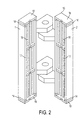
- a drawn optical fiber 40 is vertically provided to a cooling device 10 comprising two hingedly connected half shells 1 and 2 which are maintained in a closed position during an optical fiber cooling operation.
- the half shells form a housing body 20 having a series of three inner cooling chambers 22, 24 and 26, an upper end portion 18, a lower end portion 19 and a plurality of side walls 17.
- An axial through hole 15 extends from the upper end portion 18 of the housing body 20 wherein an optical fiber 40 enters the cooling tube, to the lower end portion 19 of the housing body 20 wherein the optical fiber 40 exits the cooling tube.
- the axial through hole 15 leads to the first inner cooling chamber 22 of the series of three inner cooling chambers 22, 24 and 26.
- the inner cooling chambers 22, 24 and 26 are separated from each other by separating walls 12 formed from an insulating material (e.g., Teflon).
- Each of the separating walls 12 are provided with a central opening 30 corresponding to the axial through hole 15 thereby allowing the optical fiber 40 to be sequentially transported through each of the inner cooling chambers 22, 24 and 26.
- Each of the inner cooling chambers is filled with a gaseous medium which injected though gas injection holes 50 corresponding to each of the inner cooling chambers 22, 24 and 26.
- gaseous medium which injected though gas injection holes 50 corresponding to each of the inner cooling chambers 22, 24 and 26.
- helium is utilized as the gaseous medium because of its high heat transfer coefficient although air or other types of gas may be utilized.
- the helium gas Prior to injection through the gas injection holes 50 into the inner cooling chambers 22, 24 and 26, the helium gas may be cooled to a predetermined temperature.
- the helium gas inside of the inner cooling chambers 22, 24 and 26 is cooled by twenty two copper pipes 16 (i.e., eleven pipes 16 in each of the two half shells 1 and 2 forming the housing body 20) through which a cooling liquid is circulated by coolant lines 4. That is, the helium gas transfers thermal energy from the optical fiber 40 to the outer walls of the copper pipes 16.
- the preferred embodiment utilizes twenty two copper pipes, any number of copper pipes 16 may be employed with the goal maximizing cooling effect (i.e., providing maximum number of the number copper pipes 16 in the space available inside of the inner cooling chambers 22, 24 and 26).
- the copper tubes 16 are installed inside the housing body 20 and extend from the upper end 18 to the lower end 19 of the housing body 20 so that they run the full height of the cooling device 10.
- a refrigerant mixture of water and Ethylene Glycol at a ratio of 1:1 is circulated through the copper pipes 16 to remove heat from the helium gas.
- the mixture of water and Ethylene Glycol Prior to entering the cooling device 10, the mixture of water and Ethylene Glycol is chilled to a predetermined temperature, zero degrees Celsius in the preferred embodiment, by a refrigerant cooling unit (not shown) which circulates the refrigerant mixture through the cooper pipes 16.
- a large number of copper pipes 16 e.g., twenty two
- the low temperature of the refrigerant mixture circulated through the copper pipes 16 combined with greater surface exchange provided by the large number of copper pipes 16 results in a lower consumption of transfer fluid (refrigerant) as compared with conventional cooling devices.
- the separating walls 12 provide structural stability to the copper tubes 16 by maintaining the straightness of the copper tubes 16 throughout the length of the housing body 20.
- the copper pipes 16 are positioned between the gas injection holes 50 through which the helium gas is injected into each of the inner chambers 22, 24, and 26 and the axial through hole 15 through which the optical fiber 40 passes. More particularly, the pipes 16 are positioned so that a line cannot extend from the injection holes 50 to the axial through hole 15. Therefore, the gaseous medium is prevented from being blown directly against the optical fiber 40 as it passes through the inner cooling chambers 22, 24 and 26. As a result, vibration of the optical fiber 40 is greatly reduced thereby permitting the diameter of the axial through hole 15 to be reduced in size as compared to conventional cooling devices.
- the smaller size of the axial through hole 15 allows the helium gas surrounding the optical fiber 40 to be stripped away as the optical fiber 40 passes through the separating walls 12 between the inner cooling chambers 22, 24 and 26 thereby maximizing the cooling efficiency per unit consumption of coolant gas.
- the side walls 17 of the housing body are made of aluminum while the upper and lower end portions 18 and 19 are made of brass.
- Insulating plates 14 are disposed between the side walls of the housing body and the upper and lower end portions 18 and 19 of the housing body 20. Together with the insulated separating walls 12, the insulating plates 14 help prevent condensation from forming on the outer surface of the housing body 20 by preventing direct contact between the cool parts and the frame (i.e., the side walls 17 and the upper and lower end portions 18 and 19) the of the cooling device 10.
- insulation e.g., insulating tape, may be provided the outer surface of the side walls 17 and the upper and lower end portions 18 and 19 of the cooling device 10 to prevent the formation of condensation. Accordingly, water is prevented from dripping down onto the optical fiber 40 as it is passed through the cooling device 10.
- the helium gas is simultaneously injected into each of the inner cooling chambers 22, 24 and 26 via the gas injections holes 50 while the coolant liquid is circulated through the copper pipes 16 to cool the helium gas.
- the optical fiber 40 drawn from an optical fiber preform enters the cooling device 10 via the axial through hole 15 at the upper end 18 of the housing body 20.
- the helium gas in the first inner cooling chamber 22 absorbs heat from the optical fiber 40 thereby reducing the temperature of the optical fiber 40.
- heat is extracted from the optical fiber 40 to the copper pipes 16 by the helium gas injected into the inner cooling chambers 22, 24 and 26.
- the helium gas surrounding the optical fiber 40 is stripped away resulting in greater heat exchange.
- the helium gas in the second and third inner cooling chambers 24 and 26 absorbs heat from the optical fiber 40 as it passed through the second and third inner cooling chambers 24 and 26. Because the optical fiber 40 is sequentially cooled as it passes through each of the inner cooling chambers 22, 24 and 26, it follows that the helium gas in the first inner cooling chamber 22 will be warmer than the helium gas in the second inner cooling chamber 24 since the temperature of the optical fiber 40 is reduced by the first inner cooling chamber 22 prior to entering the second inner cooling chamber 24.
- the helium gas in the second inner cooling chamber 24 will be warmer than the helium gas in the third inner cooling chamber 26 since the temperature of the optical fiber 40 is reduced by the first and second inner cooling chambers 22 and 24 prior to entering the third inner cooling chamber 26.
- the helium gas in the first inner cooling chamber 22 will absorb more heat than the helium gas in the second inner cooling chamber 24.
- the temperature of the optical fiber 40 is sequentially reduced as it passed through each of the inner cooling chambers 22, 24 and 26.
- the draw speed of the optical fiber 40 is increased to a predetermined speed at which point one of the half shells 1 of the cooling device 10 is closed and the portion of the closed half shell 1 corresponding to the axial through hole 15 is aligned with the optical fiber.
- the draw speed and the tension of the optical fiber is increased. It should be noted that the draw speed and the tension of the optical fiber 40 have a linear relation wherein as the draw speed increases the tension also increases. When the draw speed reaches a second predetermined level, the other half shell 2 is closed.
- optical fiber 40 By waiting for the draw speed of optical fiber 40 to reach the second predetermined level, it is possible to ensure that the optical fiber 40 is under proper tension in order to maintain the straightness of the optical fiber 40 and prevent vibration.
- the helium gas is then injected through the gas injection holes 50 into each of the inner cooling chambers 22, 24 and 26 and the cooling liquid is circulated through the copper tubes 16 to begin the cooling operation.
Landscapes
- Engineering & Computer Science (AREA)
- Chemical & Material Sciences (AREA)
- Manufacturing & Machinery (AREA)
- Life Sciences & Earth Sciences (AREA)
- General Life Sciences & Earth Sciences (AREA)
- Geochemistry & Mineralogy (AREA)
- Physics & Mathematics (AREA)
- Thermal Sciences (AREA)
- Materials Engineering (AREA)
- Organic Chemistry (AREA)
- Surface Treatment Of Glass Fibres Or Filaments (AREA)
- Manufacture, Treatment Of Glass Fibers (AREA)
- Optical Fibers, Optical Fiber Cores, And Optical Fiber Bundles (AREA)
Abstract
Description
Claims (13)
- An apparatus for cooling an optical fiber comprising:an housing body comprising a plurality of inner cooling chambers, a plurality of gas injection holes through which gas is injected into each of the inner cooling chambers, and an axial through hole for the axial passage therethrough of an optical fiber to be cooled, said axial through hole extending through each of the inner cooling chambers; anda plurality of coolant pipes through which a liquid coolant flows to remove heat from said inner cooling chambers, said coolant pipes extending through each of said inner cooling chambers and being disposed between said gas injection holes and said axial through hole so that the gas which injected into the inner cooling chambers through the gas injection holes is not blown directly on said optical fiber
- An apparatus for cooling an optical fiber as claimed in claim 1, wherein said housing body further comprises a plurality of partition walls interposed between adjacent ones of said inner cooling chambers to separate said adjacent ones of said inner cooling chambers from each other, said axial through hole and said coolant pipes passing through each of said partition walls.
- An apparatus for cooling an optical fiber as claimed in claim 1, wherein said housing body comprises two hingedly connected half shells which are closed together to form said housing body.
- An apparatus for cooling an optical fiber as claimed in claim 2, wherein said plate walls are formed of an insulating material.
- An apparatus as claimed in claim 1, wherein said liquid coolant which flows through said coolant pipes comprises a mixture of water and Ethylene Glycol.
- An apparatus for cooling an optical fiber as claimed in claim 1, wherein said mixture of water and Ethylene Glycol is chilled to a temperature of zero degrees Celsius.
- An apparatus for cooling an optical fiber as claimed in claim 1, wherein said gas which is injected through said gas injection holes into each of said inner cooling chambers is helium.
- An apparatus as claimed in claim 1, wherein said housing body comprises a plurality of side walls in which said gas injection holes are disposed, an upper end portion through which said optical fiber is introduced to said axial through hole, a lower end portion through which said optical fiber exits said axial through, and a plurality of insulating plates disposed between the side walls and the upper and lower end portions.
- An apparatus for cooling an optical fiber as claimed in claim 8, wherein outer surfaces of the side walls and the upper and lower end portions of the housing body are covered with an insulating material.
- An apparatus for cooling an optical fiber comprising:an housing body comprising a plurality of inner cooling chambers, a plurality of gas injection holes through which gas is injected into each of the inner cooling chambers, and an axial through hole for the axial passage therethrough of an optical fiber to be cooled, said axial through hole extending through each of the inner cooling chambers; anda plurality of coolant pipes through which a liquid coolant flows to remove heat from said inner cooling chambers, said coolant pipes extending through each of said inner cooling chambers and being disposed between said gas injection holes and said axial through hole so that the flow of the gas injected into the inner cooling chambers through the gas injection holes is disrupted by the coolant pipes to prevent the gas from being blown directly on the optical fiber.
- An apparatus for cooling an optical fiber as claimed in claim 10, wherein said housing body further comprises a plurality of partition walls interposed between adjacent ones of said inner cooling chambers to separate said adjacent ones of said inner cooling chambers from each other, said axial through hole and said coolant pipes passing through each of said partition walls.
- A method for cooling an optical fiber using a cooling apparatus comprising a housing body having a plurality of inner cooling chambers, an axial through hole extending through each of the inner cooling chambers for the axial passage of the optical fiber, a plurality of gas injection holes, and a plurality of pipes extending through each of said inner cooling chambers for the through flow of a liquid coolant, the method comprising sequentially transporting the optical fiber through each of said inner chambers via the axial through hole while injecting gas into said chambers, wherein the pipes are disposed between the gas injection holes and the axial through hole so that the gas which is injected into the inner cooling chambers via the gas injection holes is blown against the pipes and not directly on the optical fiber.
- A method of cooling an optical fiber as claimed in claim 12, further comprising circulating the liquid coolant through said pipes, wherein the gas transfers thermal energy from said optical fiber to said pipes to reduce the temperature of said optical fiber.
Applications Claiming Priority (2)
| Application Number | Priority Date | Filing Date | Title |
|---|---|---|---|
| US639344 | 2000-08-16 | ||
| US09/639,344 US6546758B1 (en) | 2000-08-16 | 2000-08-16 | Multi-chamber fiber cooling apparatus |
Publications (2)
| Publication Number | Publication Date |
|---|---|
| EP1180500A2 true EP1180500A2 (en) | 2002-02-20 |
| EP1180500A3 EP1180500A3 (en) | 2002-05-15 |
Family
ID=24563722
Family Applications (1)
| Application Number | Title | Priority Date | Filing Date |
|---|---|---|---|
| EP01401992A Withdrawn EP1180500A3 (en) | 2000-08-16 | 2001-07-24 | Method and apparatus for cooling an optical fibre during drawing using a multi-chamber cooler |
Country Status (5)
| Country | Link |
|---|---|
| US (1) | US6546758B1 (en) |
| EP (1) | EP1180500A3 (en) |
| JP (1) | JP2002104837A (en) |
| CN (1) | CN1338441A (en) |
| BR (1) | BR0103163A (en) |
Cited By (4)
| Publication number | Priority date | Publication date | Assignee | Title |
|---|---|---|---|---|
| EP1382581A1 (en) * | 2002-07-18 | 2004-01-21 | Samsung Electronics Co., Ltd. | Cooling apparatus for high-speed drawing of optical fiber |
| WO2003080523A3 (en) * | 2002-03-25 | 2004-09-30 | Air Liquide | Method and apparatus for cooling of optical fiber |
| CN105293889A (en) * | 2014-06-18 | 2016-02-03 | 住友电气工业株式会社 | Cooling device for fibers and manufacture method of fibers |
| WO2017132295A3 (en) * | 2016-01-29 | 2017-09-21 | Corning Incorporated | Thermal energy control system for an optical fiber |
Families Citing this family (10)
| Publication number | Priority date | Publication date | Assignee | Title |
|---|---|---|---|---|
| US6370920B1 (en) * | 1999-04-28 | 2002-04-16 | Alcatel | Apparatus to improve degree of cure for ultraviolet curable optical fiber coating by actively removing heat from the coating during irradiation |
| FR2838182B1 (en) * | 2002-04-08 | 2006-09-29 | Cit Alcatel | FIBER OPTIC COOLING TUBE |
| CN1273399C (en) * | 2002-10-23 | 2006-09-06 | 株式会社神户制钢所 | Fibre-optical base material manufacturing device |
| US20070113589A1 (en) * | 2005-11-18 | 2007-05-24 | Paganessi Joseph E | Gas Control Device and Corresponding Method for Recovering Coolant Gases in a Fiber Coolant System |
| WO2008097455A1 (en) * | 2007-02-05 | 2008-08-14 | Intelligent Bio-Systems, Inc. | Detection device and methods of use |
| CN100581009C (en) * | 2008-10-22 | 2010-01-13 | 中国科学院上海光学精密机械研究所 | Cylindrical optical fiber overall cooling device |
| CN103176240B (en) * | 2012-12-28 | 2015-10-28 | 清华大学 | For the cooling device of optical fiber |
| CN105884187B (en) * | 2016-04-12 | 2018-06-26 | 杭州富通通信技术股份有限公司 | Fiber drawing process |
| CN107521096A (en) * | 2017-09-30 | 2017-12-29 | 窦鹤鸿 | A kind of cooling device and 3D printer |
| CN109836053B (en) * | 2018-12-18 | 2024-05-07 | 中天科技光纤有限公司 | Cooling system and method of using the same |
Family Cites Families (21)
| Publication number | Priority date | Publication date | Assignee | Title |
|---|---|---|---|---|
| US2983497A (en) * | 1954-02-01 | 1961-05-09 | Midland Ross Corp | Cooling of moving strip |
| US3440685A (en) | 1966-12-28 | 1969-04-29 | Monsanto Co | Method and apparatus for quenching filaments |
| US3574581A (en) * | 1968-09-13 | 1971-04-13 | Ppg Industries Inc | Bushing for use in extruding fibers |
| DE2361042C3 (en) * | 1973-12-07 | 1980-07-31 | Schloemann-Siemag Ag, 4000 Duesseldorf | Device for cooling high-speed wire rod |
| US4050915A (en) | 1976-10-04 | 1977-09-27 | The Dow Chemical Company | Ferrule and use thereof for cooling a melt spun hollow glass fiber as it emerges from a spinnerette |
| US4514205A (en) | 1981-11-05 | 1985-04-30 | Corning Glass Works | Fiber cooling apparatus |
| US4761168A (en) * | 1986-09-22 | 1988-08-02 | American Telephone And Telegraph Company, At&T Bell Laboratories | Optical fiber manufacturing technique |
| US4792347A (en) | 1986-09-25 | 1988-12-20 | Corning Glass Works | Method for coating optical waveguide fiber |
| US4824457A (en) | 1987-06-05 | 1989-04-25 | Ppg Industries, Inc. | Method and apparatus for controlling thermal environment in a glass fiber forming process |
| FI78893C (en) * | 1987-09-08 | 1989-10-10 | Nokia Oy Ab | Method and apparatus for cooling an optical fiber. |
| US4838918A (en) * | 1987-12-01 | 1989-06-13 | Alcatel Na | Inert atmosphere cooler for optical fibers |
| DE3919953A1 (en) * | 1989-06-19 | 1990-12-20 | Rheydt Kabelwerk Ag | Cooling device for drawn light-conducting fibre - has internal body which can be opened into two halves surrounded by outer coolant body |
| JP2805869B2 (en) | 1989-08-01 | 1998-09-30 | 住友電気工業株式会社 | Optical fiber cooling device |
| US5043001A (en) | 1990-05-29 | 1991-08-27 | Corning Incorporated | Method and apparatus for fiber cooling |
| JP2793408B2 (en) * | 1992-01-13 | 1998-09-03 | 株式会社フジクラ | Optical fiber drawing equipment |
| US5314515A (en) | 1992-07-14 | 1994-05-24 | Corning Incorporated | Method and apparatus for fiber cooling |
| GB2287244B (en) | 1994-03-05 | 1997-07-23 | Northern Telecom Ltd | Filament cooler |
| JPH09142892A (en) | 1995-11-28 | 1997-06-03 | Furukawa Electric Co Ltd:The | Coated optical fiber manufacturing apparatus and manufacturing method |
| JPH10101360A (en) * | 1996-09-30 | 1998-04-21 | Yazaki Corp | Method and apparatus for cooling optical fiber |
| DE19727574A1 (en) | 1997-06-28 | 1999-01-07 | Alsthom Cge Alcatel | Device and method for controlling the coating thickness of an optical fiber |
| US6370920B1 (en) * | 1999-04-28 | 2002-04-16 | Alcatel | Apparatus to improve degree of cure for ultraviolet curable optical fiber coating by actively removing heat from the coating during irradiation |
-
2000
- 2000-08-16 US US09/639,344 patent/US6546758B1/en not_active Expired - Fee Related
-
2001
- 2001-07-18 JP JP2001218730A patent/JP2002104837A/en not_active Withdrawn
- 2001-07-24 EP EP01401992A patent/EP1180500A3/en not_active Withdrawn
- 2001-07-31 BR BR0103163-5A patent/BR0103163A/en not_active Application Discontinuation
- 2001-08-01 CN CN01124904A patent/CN1338441A/en active Pending
Cited By (5)
| Publication number | Priority date | Publication date | Assignee | Title |
|---|---|---|---|---|
| WO2003080523A3 (en) * | 2002-03-25 | 2004-09-30 | Air Liquide | Method and apparatus for cooling of optical fiber |
| EP1382581A1 (en) * | 2002-07-18 | 2004-01-21 | Samsung Electronics Co., Ltd. | Cooling apparatus for high-speed drawing of optical fiber |
| CN105293889A (en) * | 2014-06-18 | 2016-02-03 | 住友电气工业株式会社 | Cooling device for fibers and manufacture method of fibers |
| CN105293889B (en) * | 2014-06-18 | 2019-08-16 | 住友电气工业株式会社 | The manufacturing method of optical fiber cooling device and optical fiber |
| WO2017132295A3 (en) * | 2016-01-29 | 2017-09-21 | Corning Incorporated | Thermal energy control system for an optical fiber |
Also Published As
| Publication number | Publication date |
|---|---|
| US6546758B1 (en) | 2003-04-15 |
| JP2002104837A (en) | 2002-04-10 |
| CN1338441A (en) | 2002-03-06 |
| BR0103163A (en) | 2002-04-02 |
| EP1180500A3 (en) | 2002-05-15 |
Similar Documents
| Publication | Publication Date | Title |
|---|---|---|
| US6546758B1 (en) | Multi-chamber fiber cooling apparatus | |
| US4664689A (en) | Method and apparatus for rapidly cooling optical fiber | |
| CA1315534C (en) | Method of and an apparatus for cooling an optical fibre | |
| US6984264B2 (en) | Single crystal pulling device and method and superconducting magnet | |
| CN110683752B (en) | Optical fiber drawing cooling system and cooling method thereof | |
| EP1032541B1 (en) | Method and apparatus for cooling optical fibers | |
| KR100248066B1 (en) | Cooler of optical fiber draw tower | |
| CN103339073A (en) | Improved optical fiber cooling device | |
| WO2022104969A1 (en) | Adjustable water cooling device for cable production | |
| US4838918A (en) | Inert atmosphere cooler for optical fibers | |
| US20030188556A1 (en) | Optical fiber cooling tube | |
| EP0016483A1 (en) | 3He-4He dilution refrigerator | |
| JPH0236923A (en) | Manufacturing device for heat-shrinkable tube | |
| CN85101537A (en) | Fibre-optic manufacture method and equipment with protective coating | |
| US20040011084A1 (en) | Cooling apparatus for high-speed drawing | |
| US20030205066A1 (en) | Method and apparatus for efficient cooling of optical fiber during its manufacture | |
| CN221873162U (en) | Heat shrink tube expansion device | |
| CN210885814U (en) | Optical fiber drawing cooling system | |
| KR102813441B1 (en) | Cooler for high temperature heat pipe and apparatus for thermal performance test including the same | |
| CN223871279U (en) | Quick cooling device after thermal shrinkage of cable outer sheath | |
| KR20200056963A (en) | Header of refrigerator for cooling liquid nitrogen | |
| CN217029681U (en) | Water-cooled bearing seat for turbine regenerator | |
| CN223524739U (en) | Cooling device | |
| SU1265564A1 (en) | Method for checking quality of vacuum flasks | |
| CN113223774A (en) | Superconducting cable and cooling method thereof |
Legal Events
| Date | Code | Title | Description |
|---|---|---|---|
| PUAI | Public reference made under article 153(3) epc to a published international application that has entered the european phase |
Free format text: ORIGINAL CODE: 0009012 |
|
| AK | Designated contracting states |
Kind code of ref document: A2 Designated state(s): AT BE CH CY DE DK ES FI FR GB GR IE IT LI LU MC NL PT SE TR |
|
| AX | Request for extension of the european patent |
Free format text: AL;LT;LV;MK;RO;SI |
|
| PUAL | Search report despatched |
Free format text: ORIGINAL CODE: 0009013 |
|
| AK | Designated contracting states |
Kind code of ref document: A3 Designated state(s): AT BE CH CY DE DK ES FI FR GB GR IE IT LI LU MC NL PT SE TR |
|
| AX | Request for extension of the european patent |
Free format text: AL;LT;LV;MK;RO;SI |
|
| 17P | Request for examination filed |
Effective date: 20021021 |
|
| AKX | Designation fees paid |
Designated state(s): AT BE CH CY DE DK ES FI FR GB GR IE IT LI LU MC NL PT SE TR |
|
| STAA | Information on the status of an ep patent application or granted ep patent |
Free format text: STATUS: THE APPLICATION IS DEEMED TO BE WITHDRAWN |
|
| 18D | Application deemed to be withdrawn |
Effective date: 20040203 |