EP1179956A1 - Scanner having a vertical rest position - Google Patents
Scanner having a vertical rest position Download PDFInfo
- Publication number
- EP1179956A1 EP1179956A1 EP00204669A EP00204669A EP1179956A1 EP 1179956 A1 EP1179956 A1 EP 1179956A1 EP 00204669 A EP00204669 A EP 00204669A EP 00204669 A EP00204669 A EP 00204669A EP 1179956 A1 EP1179956 A1 EP 1179956A1
- Authority
- EP
- European Patent Office
- Prior art keywords
- scanner
- chassis
- base portion
- axis
- rest position
- Prior art date
- Legal status (The legal status is an assumption and is not a legal conclusion. Google has not performed a legal analysis and makes no representation as to the accuracy of the status listed.)
- Granted
Links
- 230000001419 dependent effect Effects 0.000 claims description 2
- 238000010276 construction Methods 0.000 description 2
- 230000002093 peripheral effect Effects 0.000 description 2
- 241001479434 Agfa Species 0.000 description 1
- 239000011521 glass Substances 0.000 description 1
- 230000005484 gravity Effects 0.000 description 1
- 238000000034 method Methods 0.000 description 1
- 238000012986 modification Methods 0.000 description 1
- 230000004048 modification Effects 0.000 description 1
Images


Classifications
-
- H—ELECTRICITY
- H04—ELECTRIC COMMUNICATION TECHNIQUE
- H04N—PICTORIAL COMMUNICATION, e.g. TELEVISION
- H04N1/00—Scanning, transmission or reproduction of documents or the like, e.g. facsimile transmission; Details thereof
- H04N1/00519—Constructional details not otherwise provided for, e.g. housings, covers
- H04N1/00525—Providing a more compact apparatus, e.g. sheet discharge tray in cover
-
- H—ELECTRICITY
- H04—ELECTRIC COMMUNICATION TECHNIQUE
- H04N—PICTORIAL COMMUNICATION, e.g. TELEVISION
- H04N2201/00—Indexing scheme relating to scanning, transmission or reproduction of documents or the like, and to details thereof
- H04N2201/04—Scanning arrangements
- H04N2201/0402—Arrangements not specific to a particular one of the scanning methods covered by groups H04N1/04 - H04N1/207
- H04N2201/045—Mounting the scanning elements in a collapsible or foldable structure, e.g. for ease of transportation
Definitions
- the present invention relates to the field of image scanning systems, and in particular to a flatbed desktop scanner.
- a flatbed desktop scanner as known in the art such as the Agfa SnapScanTM 1212p, contains a substantially rectangular base portion and a document lid. The base portion rests on the desk. A photo, a printed image or another object is positioned on the base portion, the document lid is closed and the object is scanned. The digital data obtained from the scan can then be processed by a computer, can be printed, can be sent over a network such as the Internet, etc.
- a disadvantage of such a conventional scanner is that it requires quite some desk space, even when not in use - very often, a scanner is used only part of the time. Moreover, the scanner is usually connected to a computer that stands on the same desk and this computer often has other peripheral equipment, such as a printer. Such a combination of a computer and its peripheral equipment requires much space, and therefore it is important to save desk space.
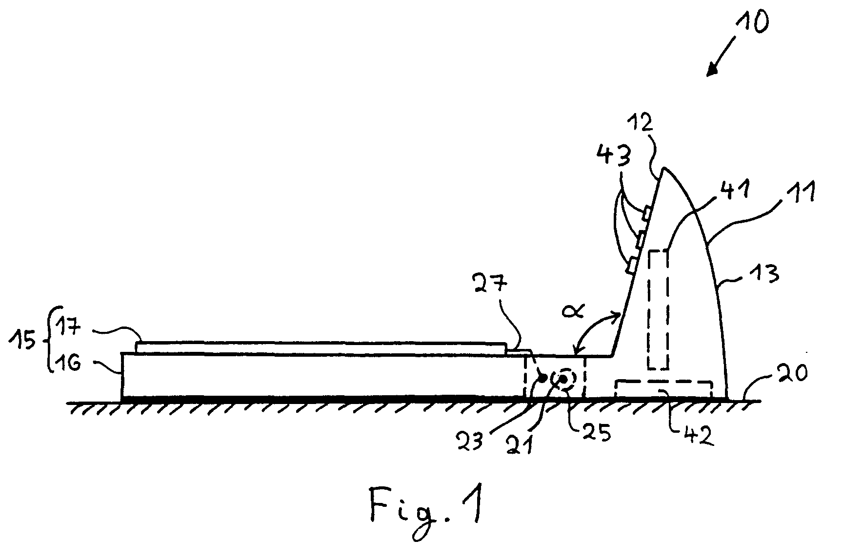
- Figs. 1 to 4 illustrate a first embodiment of a scanner 10 in accordance with the invention.
- the scanner 10 contains a chassis 11 and a body 15.
- the body 15 may contain a base portion 16, to support the document that is to be scanned, and a document lid 17, to cover the document in order to avoid the influence of ambient light during scanning.
- the body 15 is movably connected to the chassis 11 so that it can be moved from a substantially horizontal operative position, wherein the body 15 is supported by the desk 20 as shown in Fig. 1, to a substantially vertical rest position, as shown in Fig. 2. In the substantially vertical rest position, the scanner requires much less desk space; the gain of desk space can amount to more than 50 %, even to more than 60 % in a preferred embodiment.
- the body 15 When the scanner 10 is not in use, the body 15 is preferably in its substantially vertical rest position, as shown in Fig. 2. To operate the scanner, the body 15 is then moved from the substantially vertical rest position to the substantially horizontal operative position, which is illustrated by Fig. 1. If no documents have to be scanned for some time, the user preferably returns the body 15 to its substantially vertical rest position, in order to save desk space. Of course, the user may also choose to keep the body 15 in its substantially horizontal operative position for an arbitrary length of time.
- documents may not only be scanned in the substantially horizontal operative position (shown in Fig. 1) but also in the substantially vertical rest position (shown in Fig. 2).
- the scanner 10 includes means to hold the document in its substantially vertical position, against gravity, while it is scanned.
- Such holding means may make use of electrostatic attraction - e.g. for paper documents - or other means as known in the art may be used.
- connection means 25 In a first embodiment, shown in Figs. 1 to 3, the base portion 16 is pivotally connected to the chassis 11 by connection means 25, so that the base portion 16 can pivot around axis 21.
- Fig. 3 shows a specific embodiment of the connection means 25: two pins 26, which are part of the chassis 11, and two corresponding openings in the base portion 16.
- any other connection means 25 as known in the art may be used.
- the document lid 17 is pivotally connected to the chassis 11 so that it can pivot around axis 23.
- the connection is realised in the embodiment of Figs. 1 to 3 by two elements 27 that have the shape of an oblique L; other connection means as known in the art may be also used.
- axis 23 coincides with axis 21 so that the base portion 16 and the document lid 17 pivot around the same axis. This has the advantage that the document lid 17 does not move with respect to the base portion 16 when moving the body between its substantially horizontal operative position and its substantially vertical rest position.
- the document lid 17 is not connected to the chassis 11 but instead is pivotally connected to the base portion 16, so that it can pivot around an axis 22.
- the body 15 makes an angle ⁇ with the substantially horizontal plane of the desk 20 that is preferably between 60° and 120°. More preferably, the front side 12 of the chassis 11, which is the side turned towards the body 15, is inclined slightly backwards, as shown in Fig. 1, so that the angle ⁇ is between 90° and 120°; most preferably ⁇ is between 95° and 115°. Such an angle ensures good stability of the body 15 in the substantially vertical rest position.
- the chassis 11 contains at least a portion of the electronic hardware 41 for operating the scanner. This is advantageous since the body 15, not containing this hardware, then weighs less and is therefore easier to move.
- the chassis 11 may contain the electronics main board and may have, preferably on its back side 13 which is the side turned away from body 15, a connector for both data-transmission and power.
- the chassis 11 may have two feet 14 to enlarge stability of the scanner 10 in the substantially vertical rest position.
- a weight 42 is put near the bottom of the chassis 11 to enlarge stability even more.
- the user interface of the scanner is preferably contained at least partly in the chassis 11. Advantages are that the user interface is located near the electronic hardware 41, so that the electrical connections between the user interface and the electronic hardware may be short, and that the body 15 may have a simple construction and may weigh less.
- the user interface may comprise one or more buttons 43, which can be pushed to operate the scanner. As shown in Figs. 1 and 4, the pushbuttons 43 may be located on the front side 12 of the chassis 11.
- the base portion 16 may contain, as known in the art, a scan-carriage, a sensor and a glass plate, upon which the document is put that will be scanned.
- the scan-carriage 18 is guided by a single guide rail 19 that occupies a substantially central position in the base portion 16.
- the document lid 17 preferably has low weight and high stiffness, which can be achieved by known mechanical construction techniques.
- Fig. 5 illustrates a second embodiment of the invention wherein the body 15 is not pivotally connected to the chassis 11, as is the case in the first embodiment that was discussed with reference to Figs. 1 to 3. Instead, as shown schematically in Fig. 5, body 15 is movably connected to chassis 11 by a sliding joint 28 that can itself perform a substantially rotational movement. To move body 15 from its substantially horizontal operative position (shown in Fig. 5) to its substantially vertical rest position, the user may proceed as follows. First he pulls body 15 away from chassis 11 in the sense of arrow a, until stop 29 arrives at position P.
Landscapes
- Engineering & Computer Science (AREA)
- Multimedia (AREA)
- Signal Processing (AREA)
- Facsimile Scanning Arrangements (AREA)
- Facsimiles In General (AREA)
- Image Input (AREA)
Abstract
Description
- 10 :
- scanner
- 11 :
- chassis
- 12 :
- front side
- 13 :
- back side
- 14 :
- foot
- 15 :
- body
- 16 :
- base portion
- 17 :
- document lid
- 18 :
- scan-carriage
- 19 :
- guide rail
- 20 :
- desk
- 21 :
- first axis
- 22 :
- second axis
- 23 :
- third axis
- 25 :
- connection element
- 26 :
- pin
- 27 :
- connection element
- 28 :
- sliding joint
- 29 :
- stop
- 31 :
- groove
- 41 :
- electronic hardware
- 42 :
- weight
- 43 :
- pushbutton
- 45 :
- face
- α :
- angle
- P :
- position
- a,b,c:
- arrows
Claims (8)
- A scanner (10) comprising a body (15) having a substantially horizontal operative position,
characterised in that the scanner further comprises a chassis (11) and in that the body (15) is movably connected to the chassis (11) for moving from the substantially horizontal operative position to a substantially vertical rest position. - The scanner (10) according to claim 1 wherein the body (15) comprises a base portion (16) and a document lid (17) and wherein the base portion (16) is pivotally connected to the chassis (11) for pivoting around a first axis (21).
- The scanner (10) according to any one of claims 1 to 2 wherein the document lid (17) is pivotally connected to the base portion (16) for pivoting around a second axis (22).
- The scanner (10) according to any one of claims 1 to 2 wherein the document lid (17) is pivotally connected to the chassis (11) for pivoting around a third axis (23).
- The scanner (10) according to claim 4 when dependent on claim 2 wherein the third axis (23) coincides with the first axis (21).
- The scanner (10) according to any one of the preceding claims wherein the chassis (11) comprises electronic hardware (41) for operating the scanner (10).
- The scanner (10) according to any one of the preceding claims, wherein the scanner (10) has a user interface (43) and wherein the chassis (11) comprises at least a portion of the user interface (43).
- The scanner (10) according to the preceding claim wherein the user interface (43) comprises at least one pushbutton (43).
Priority Applications (3)
| Application Number | Priority Date | Filing Date | Title |
|---|---|---|---|
| EP00204669A EP1179956B1 (en) | 2000-07-17 | 2000-12-19 | Scanner having a vertical rest position |
| JP2001213447A JP2002057857A (en) | 2000-07-17 | 2001-07-13 | Scanner having vertical stop position |
| US09/907,376 US7196828B2 (en) | 2000-07-17 | 2001-07-17 | Scanner having a vertical rest position |
Applications Claiming Priority (3)
| Application Number | Priority Date | Filing Date | Title |
|---|---|---|---|
| EP00202552 | 2000-07-17 | ||
| EP00202552 | 2000-07-17 | ||
| EP00204669A EP1179956B1 (en) | 2000-07-17 | 2000-12-19 | Scanner having a vertical rest position |
Publications (2)
| Publication Number | Publication Date |
|---|---|
| EP1179956A1 true EP1179956A1 (en) | 2002-02-13 |
| EP1179956B1 EP1179956B1 (en) | 2007-04-04 |
Family
ID=26072514
Family Applications (1)
| Application Number | Title | Priority Date | Filing Date |
|---|---|---|---|
| EP00204669A Expired - Lifetime EP1179956B1 (en) | 2000-07-17 | 2000-12-19 | Scanner having a vertical rest position |
Country Status (2)
| Country | Link |
|---|---|
| EP (1) | EP1179956B1 (en) |
| JP (1) | JP2002057857A (en) |
Cited By (1)
| Publication number | Priority date | Publication date | Assignee | Title |
|---|---|---|---|---|
| CN115334208A (en) * | 2022-06-20 | 2022-11-11 | 厦门升光信息科技有限公司 | Verifying attachment of intelligence file |
Citations (2)
| Publication number | Priority date | Publication date | Assignee | Title |
|---|---|---|---|---|
| US4611246A (en) * | 1984-11-14 | 1986-09-09 | Casio Computer Co., Ltd. | Handy reader/printer apparatus |
| US4750047A (en) * | 1985-10-25 | 1988-06-07 | Sharp Kabushiki Kaisha | Folding facsimile |
Family Cites Families (1)
| Publication number | Priority date | Publication date | Assignee | Title |
|---|---|---|---|---|
| US6040572A (en) * | 1998-05-21 | 2000-03-21 | Hewlett-Packard Company | Notebook styled scanner |
-
2000
- 2000-12-19 EP EP00204669A patent/EP1179956B1/en not_active Expired - Lifetime
-
2001
- 2001-07-13 JP JP2001213447A patent/JP2002057857A/en active Pending
Patent Citations (2)
| Publication number | Priority date | Publication date | Assignee | Title |
|---|---|---|---|---|
| US4611246A (en) * | 1984-11-14 | 1986-09-09 | Casio Computer Co., Ltd. | Handy reader/printer apparatus |
| US4750047A (en) * | 1985-10-25 | 1988-06-07 | Sharp Kabushiki Kaisha | Folding facsimile |
Cited By (2)
| Publication number | Priority date | Publication date | Assignee | Title |
|---|---|---|---|---|
| CN115334208A (en) * | 2022-06-20 | 2022-11-11 | 厦门升光信息科技有限公司 | Verifying attachment of intelligence file |
| CN115334208B (en) * | 2022-06-20 | 2024-05-07 | 厦门升光信息科技有限公司 | Intelligent document's verifying attachment |
Also Published As
| Publication number | Publication date |
|---|---|
| JP2002057857A (en) | 2002-02-22 |
| EP1179956B1 (en) | 2007-04-04 |
Similar Documents
| Publication | Publication Date | Title |
|---|---|---|
| US5115374A (en) | Portable computer including, for facsimile transmission, a document scanner integral with the display module | |
| CN101668101B (en) | Scanner device | |
| US5490036A (en) | Portable computer with tiltable keyboard structure having releasably engageable latch assembly members extending therefrom | |
| US7196828B2 (en) | Scanner having a vertical rest position | |
| US6661539B1 (en) | Vertically oriented document scanner | |
| JP2000200118A (en) | Combined body of portable computer and movable scanner | |
| US6489949B1 (en) | Multi-functional keyboard | |
| US7423786B2 (en) | Optical scanner with inclined platen | |
| US6947185B2 (en) | Scanner having a document cover with a flap door hinged thereto | |
| US20050031390A1 (en) | Image capture device with a telescopic hinge | |
| EP1179956B1 (en) | Scanner having a vertical rest position | |
| JP3170986B2 (en) | Device having a tiltable display device | |
| US7310171B2 (en) | Document surface micro-adjust mechanism | |
| US7212295B2 (en) | Keyboard for imaging devices | |
| US7325742B2 (en) | Portable data processing device capable of acquiring images and supporting human hands | |
| US6335806B1 (en) | Document pressing structure in scanning device | |
| US20100014125A1 (en) | Image Display Device with Scanning Function | |
| JPH09244161A (en) | Image reading device | |
| JP2933092B2 (en) | Document reading device | |
| TWI307238B (en) | Image scanner having rotatable illuminantor plate | |
| JPH0793065A (en) | Electronics | |
| JP3026914B2 (en) | Keyboard tilt mechanism | |
| US20050088708A1 (en) | Scan window assembly with an open boundary | |
| US20050030593A1 (en) | Image capture device with stand | |
| US20060082834A1 (en) | Scanners |
Legal Events
| Date | Code | Title | Description |
|---|---|---|---|
| PUAI | Public reference made under article 153(3) epc to a published international application that has entered the european phase |
Free format text: ORIGINAL CODE: 0009012 |
|
| AK | Designated contracting states |
Kind code of ref document: A1 Designated state(s): DE FR GB Kind code of ref document: A1 Designated state(s): AT BE CH CY DE DK ES FI FR GB GR IE IT LI LU MC NL PT SE TR |
|
| AX | Request for extension of the european patent |
Free format text: AL;LT;LV;MK;RO;SI |
|
| RAP1 | Party data changed (applicant data changed or rights of an application transferred) |
Owner name: AGFA-GEVAERT |
|
| 17P | Request for examination filed |
Effective date: 20020813 |
|
| AKX | Designation fees paid |
Free format text: DE FR GB |
|
| GRAP | Despatch of communication of intention to grant a patent |
Free format text: ORIGINAL CODE: EPIDOSNIGR1 |
|
| GRAS | Grant fee paid |
Free format text: ORIGINAL CODE: EPIDOSNIGR3 |
|
| RAP1 | Party data changed (applicant data changed or rights of an application transferred) |
Owner name: AGFA GRAPHICS N.V. |
|
| GRAA | (expected) grant |
Free format text: ORIGINAL CODE: 0009210 |
|
| AK | Designated contracting states |
Kind code of ref document: B1 Designated state(s): DE FR GB |
|
| REG | Reference to a national code |
Ref country code: GB Ref legal event code: FG4D |
|
| RIN1 | Information on inventor provided before grant (corrected) |
Inventor name: RUBNER, KARL HEINZ Inventor name: DEBUSSCHERE, BAVO,C/O AGFA-GEVAERT N.V. |
|
| REF | Corresponds to: |
Ref document number: 60034226 Country of ref document: DE Date of ref document: 20070516 Kind code of ref document: P |
|
| ET | Fr: translation filed | ||
| PLBE | No opposition filed within time limit |
Free format text: ORIGINAL CODE: 0009261 |
|
| STAA | Information on the status of an ep patent application or granted ep patent |
Free format text: STATUS: NO OPPOSITION FILED WITHIN TIME LIMIT |
|
| 26N | No opposition filed |
Effective date: 20080107 |
|
| REG | Reference to a national code |
Ref country code: FR Ref legal event code: PLFP Year of fee payment: 16 |
|
| PGFP | Annual fee paid to national office [announced via postgrant information from national office to epo] |
Ref country code: GB Payment date: 20151023 Year of fee payment: 16 Ref country code: DE Payment date: 20151022 Year of fee payment: 16 |
|
| PGFP | Annual fee paid to national office [announced via postgrant information from national office to epo] |
Ref country code: FR Payment date: 20151020 Year of fee payment: 16 |
|
| REG | Reference to a national code |
Ref country code: DE Ref legal event code: R119 Ref document number: 60034226 Country of ref document: DE |
|
| GBPC | Gb: european patent ceased through non-payment of renewal fee |
Effective date: 20161219 |
|
| REG | Reference to a national code |
Ref country code: FR Ref legal event code: ST Effective date: 20170831 |
|
| PG25 | Lapsed in a contracting state [announced via postgrant information from national office to epo] |
Ref country code: FR Free format text: LAPSE BECAUSE OF NON-PAYMENT OF DUE FEES Effective date: 20170102 |
|
| PG25 | Lapsed in a contracting state [announced via postgrant information from national office to epo] |
Ref country code: GB Free format text: LAPSE BECAUSE OF NON-PAYMENT OF DUE FEES Effective date: 20161219 Ref country code: DE Free format text: LAPSE BECAUSE OF NON-PAYMENT OF DUE FEES Effective date: 20170701 |