EP1179800A2 - Identification mark output apparatus - Google Patents
Identification mark output apparatus Download PDFInfo
- Publication number
- EP1179800A2 EP1179800A2 EP00311442A EP00311442A EP1179800A2 EP 1179800 A2 EP1179800 A2 EP 1179800A2 EP 00311442 A EP00311442 A EP 00311442A EP 00311442 A EP00311442 A EP 00311442A EP 1179800 A2 EP1179800 A2 EP 1179800A2
- Authority
- EP
- European Patent Office
- Prior art keywords
- code
- mark
- caption
- bar code
- character
- Prior art date
- Legal status (The legal status is an assumption and is not a legal conclusion. Google has not performed a legal analysis and makes no representation as to the accuracy of the status listed.)
- Granted
Links
Images



Classifications
-
- G—PHYSICS
- G06—COMPUTING OR CALCULATING; COUNTING
- G06K—GRAPHICAL DATA READING; PRESENTATION OF DATA; RECORD CARRIERS; HANDLING RECORD CARRIERS
- G06K1/00—Methods or arrangements for marking the record carrier in digital fashion
- G06K1/12—Methods or arrangements for marking the record carrier in digital fashion otherwise than by punching
- G06K1/121—Methods or arrangements for marking the record carrier in digital fashion otherwise than by punching by printing code marks
Definitions
- the present invention relates to an apparatus for printing and/or displaying identification marks such as bar codes. More particularly, the present invention relates to an identification mark output apparatus designed to output a bar code together with a caption (consisting of letters, figures, signs, etc) arranged adjacent to the bar code.
- conventional bar code label printers are designed to print required bar codes in accordance with one of the application standards such as NW-7, JAN, Code 3 of 9, Industrial 2 of 5, Interleaved 2 of 5 and EAN-128.
- NW-7 National National Standard
- JAN Joint NAND
- Code 3 of 9, Industrial 2 of 5, Interleaved 2 of 5 and EAN-128 According to these standards except the last one (EAN-128), the characters represented by the bar code are printed in a one-to-one correspondence to the characters represented by the caption accompanying the bar code.
- EAN-128 the last one
- the characters represented by the bar code are printed in a one-to-one correspondence to the characters represented by the caption accompanying the bar code.
- EAN-128 the last one
- the user of the conventional printer is required to enter only the data about the bar code into the host computer, but not the data about the caption.
- the characters represented by a bar code do not need to be in a one-to-one correspondence to the characters represented by the accompanying caption.
- the characters of the caption may include separation signs such as "(" and ")", whereas the characters of the bar code do not include these signs.
- the user of the printer needs to separately enter data about the bar code and data about the caption into the host computer. Based on these pieces of data, the host computer supplies two pieces of control data (i.e., control data for printing the bar code and control data for printing the caption) to the printer.
- control data i.e., control data for printing the bar code and control data for printing the caption
- the printing of the bar code and the caption may be performed based on control codes (bar code printing codes) in a text mode.
- control codes bar code printing codes
- the vertical positional adjustment of a deviated caption can only be performed by the width of one line.
- the printer may fail to recognize that the bar code and the accompanying caption belong to the common ID mark. In such an instance, when the user wishes to discontinue the printing of the ID mark upon finding erroneous entry of ID mark specifying data, the user may be able to stop the bar code printing but not the caption printing.
- Code 128 is not ideally compatible with a 1-byte character code table such as an EBCDIC-code table. Therefore, when a bar code is specified in accordance with the EBCDIC-code table, some characters (special characters) of the bar code may not be printed by a printer provided with Code 128.
- an ID mark output apparatus designed to print or display an ID mark based on a single piece of ID mark specifying data, wherein the ID mark includes a symbol and a caption in a non-one-to-one correspondence.
- an identification mark output apparatus for outputting ID marks each of which includes a symbol pattern and a caption accompanying the symbol pattern.
- the apparatus includes a data receiver for receiving a single piece of mark-specifying information corresponding to a selected ID mark, and an output device for outputting the selected ID mark.
- the apparatus is characterized in that the symbol pattern and the caption of the selected ID mark are outputted in a non-one-to-one correspondence based on the single piece of mark-specifying information.
- the output device may be provided with code-converting means for analyzing the contents of the single piece of mark-specifying information.
- the code-converting means may be provided with a plurality of code conversion tables corresponding to different code systems.
- the output device may cause a separation sign of the selected ID mark to be outputted in the caption but not in the symbol pattern.
- the symbol pattern may be a bar code.
- the single piece of mark-specifying information includes character code data and separation sign data which is separate from the character code data.
- the single piece of mark-specifying information is provided with several character codes which include separation sign code and separation sign start code preceding the separation sign code.
- the single piece of mark-specifying information may include a separation sign code for causing a predetermined separation sign to be outputted in any one of the bar code and the caption.
- the output device may be a printer and/or a monitor.
- Fig. 1 schematically showing the components of an identification mark output system embodying the present invention.
- the output system includes a computer 1, a printer 2 and a LAN (local area network) 3 connecting the computer 1 to the printer 2.
- an item identification mark A may be printed on a recording medium and/or displayed on the monitor of the computer 1.
- the computer 1 may be a personal computer, a work station or a main frame.
- the illustrated ID mark A includes a bar code A1 and a caption A2 printed under the bar code A1.
- the illustrated caption A2 includes several figures and a pair of parentheses, though the present invention is not limited to this.
- the caption A2 may include other kinds of signs, letters, etc.
- the computer 1 When operated by a user desiring to print the ID mark A, the computer 1 supplies printing data to the printer 2.
- the printing data may include ID mark specifying data or control code. This ID mark specifying data is generated in accordance with a bar code table stored in the memory (e.g. hard disk) of the computer 1.
- the printer 2 which may be an inkjet printer or laser printer designed to print ID marks on recording media, includes a CPU (central processing unit) 21, a ROM (read-only memory) 22, a RAM (random-access memory) 23, an EEPROM (electrically erasable programmable ROM) 24, an IF (interface) 25, and a printing unit 26.
- the CPU 21, ROM 22, RAM 23, EEPROM 24 and the IF 25 are connected to each other via bus lines 27 consisting of a data bus, an address bus and a control bus.
- the LAN 3 is connected to the IF 25.
- the CPU 21 controls all the other parts of the printer 2.
- the ROM 22 stores programs to be executed by the CPU 21.
- the RAM 23 provides data storage work areas for the CPU 21.
- the EEPROM 24 stores a plurality of code conversion tables including the illustrated tables 24A and 24B.
- the ID mark A is formed in accordance with EAN-128 for example.
- EAN-128 the characters of the bar code A1 and the characters of the caption A2 are not necessarily arranged in a one-to-one correspondence.
- the illustrated bar code A1 does not include characters corresponding to the parentheses "(" and ")" present in the caption A2, though the bar code A1 includes the characters corresponding to the figures "1, 0, 4, 9, 0 and 1" of the caption A2.
- Fig. 2 shows an example of a control code (ID mark specifying data) formed in accordance with an embodiment of the present invention.
- the illustrated control code includes various pieces of data representing the identification of the control code, the length of the control code, the identification of the mark A, the size of the region for printing the mark A.
- the control code also includes a flag and character codes.
- the control code ID data shows that the supplied control code is the one for performing ID mark printing.
- the control code length data shows the data length of the control code.
- the mark ID data shows what standard the ID mark A complies with.
- the print region size data shows the size of the rectangular region in which the ID mark is to be printed.
- the flag serves as control information when the ID mark is printed.
- the character codes are formed in accordance with an EBCDIC code table.
- control code shown in Fig. 2 includes separation sign-specifying sections indicated by "?1" and "?2", which are not present in conventional control codes. The technical significance of this novel feature will be described later.
- Fig. 3 shows an example of a bar code table stored in the hard disk of the computer 1.
- the illustrated table is basically the same as a conventional EBCDIC code table except for the following differences.
- the bar code table of Fig. 3 contains a number of special characters which are not present in a conventional EBCDIC code table.
- the special characters are "START * (B0-B2)", “FNC * (B3-B6)", “CODE * (B7-B9)” and “SHIFT(BA)".
- the illustrated bar code table also includes sections "BD”, “BE” and “BF” provided for designating "SEPARATION SIGN 1", “SEPARATION SIGN 2" AND “SEPARATION SIGN START", respectively. It should be noted here that the above-mentioned sections (i.e., B0-BA and BD-BF) are not used in conventional EBCDIC code tables.
- the non-illustrated CPU of the computer 1 Upon receiving a print command from the user wishing to print the ID mark A (Fig. 1), the non-illustrated CPU of the computer 1 refers to the EBCDIC-compatible bar code table of Fig. 3 to generates a single control code for the ID mark A.
- Fig. 4 shows an example of a control code generated in accordance with the EBCDIC-compatible bar code table of Fig. 3.
- the illustrated control code is the one provided for printing the ID mark A shown in Fig. 1.
- the caption A2 consists of a series of numbers (1, 0, 4, 9, 0 and 1 in this order) and parentheses (separation signs) enclosing the first two digits (1 and 0).
- codes “4D” and “5D” are placed, respectively, in the *1 section for the first separation sign and in the * 2 section for the second separation sign.
- the code “4D” represents the sign “(" in hexadecimal notation, while the code “5D” represents the sign ")" in hexadecimal notation.
- the control code of Fig. 4 also includes a character code section following the * 2 section.
- the character code section includes a number of character codes (in hexadecimal notation) based on the bar code table of Fig. 3.
- the character code section contains ten codes, namely, B0, B3, BD, F1, F0, BE, F4, F9, F0 and F1.
- the first and second codes correspond to "START A" and "FNC 1", respectively, as shown in the bar code table of Fig. 3.
- the third code "BD” means that the separation sign "4D" in the * 1 section is to be printed in the ID mark A. It should be noted here that, at this stage, it has not been determined yet whether the separation sign 4D is to be included only in the caption A2 or in the bar code A1 or in both. As will be described below, this determination is made when the given control code is subjected to the conversion based on the code conversion table 24A.
- the fourth and the fifth codes "F1" and “F0” correspond to the first and the second digits ("1" and “0") in the caption A2, respectively. In the illustrated example, these two numbers will be included both in the bar code A1 and the caption A2.
- the sixth code "BE" means that the separation sign "5D" in the *2 section is to be printed in the ID mark A. As with the first separation sign "4D", at this stage, it has not been determined yet whether the separation sign 5D is to be included only in the caption A2 or in the bar code A1 or in both.
- the seventh to the tenth codes “F4", “F9”, “F0” and “F1” correspond to the third to the sixth digits ( “4", “9”, “0” and “1") in the caption A2. As with the first and the second digits, these four numbers will also be included in both the bar code A1 and the caption A2.
- the above-mentioned control code, generated by the computer 1, is sent to the printer 2 via the LAN 3, and received by the CPU 21 of the printer.
- the CPU 21 Upon receiving the control code, the CPU 21 reads out the data contained in the control code, and analyzes the contents of the control code by referring to the code conversion table 24A.
- the conversion table 24A which is stored in the EEPROM 24 of the printer 2, is arranged in accordance with the EBCDIC-compatible bar code table stored in the computer 1.
- the code conversion table 24A which is also EBCDIC-compatible, may be arranged to associate the character codes of the control code with predetermined codes or values such as "FF", "FB", “FC”, “FD” and others.
- the third character code “BD” in the control code of Fig. 4 is associated with the code "FB” which means that the character designated as the first separation sign (*1) is to be printed only in the caption A2 but not in the bar code A1.
- the sixth character code “BE” in the control code of Fig. 4 is associated with the code “FC” which means that the second separation sign (*2) is to be printed only in the caption A2 but not in the bar code A1.
- control code of Fig. 4 contains an undefined character code
- this code is associated with the code "FF" by the conversion table 24A. In this case, the particular character will not be symbolized in any one of the bar code and the caption.
- control code of Fig. 4 contains the character code "BF”
- this code is associated with the code "FD” by the conversion table 24A.
- This code "FD” means that a subsequent character code disposed immediately after the character code "BF” in the control code is to be printed only in the caption but not in the bar code.
- the control code of Fig. 4 includes, among others, two juxtaposed character codes “BF” and “4A”, the square bracket “[” represented by the code "4A” will be printed in the caption but not in the bar code.
- the CPU 21 of the printer 2 determines whether or not the bar code ID contained in the control code shows that the control code is generated in accordance with EAN-128 (S1).
- the CPU 21 reads out the first and second separation signs from the control code (S2). These read-out separation signs are stored in the RAM 23.
- the CPU 21 reads out the character codes from the control code (S3). As doing this, the CPU 21 counts the number of the character codes and causes the result to be stored in the RAM 23. The stored number is used as a total code number pointer to determine whether or not all of the character codes has been properly processed (see S13).
- the CPU 21 refers to the code conversion table 24A, to find a corresponding value of each character code (S4).
- the CPU 21 determines whether or not the obtained value is "FF" (S5).
- the CPU 21 determines whether or not the value is "FE” (S6).
- the CPU 21 determines whether or not the value is "FB" (S7).
- the CPU 21 When the value is not "FD" (S9:NO), the CPU 21 causes the character to be included in both the bar code A1 and the caption A2 (S10). Based on the pattern address obtained from the conversion table 24A, the CPU 21 determines the amount of offset between the bar code A1 and the caption A2 (S11).
- the CPU 21 adds one to the processed-code pointer (S12), while also determining whether or not the processed-code pointer is equal to the total code number pointer (S13).
- Step 13 when the processed-code pointer shows a number smaller than the total code number pointer (S13:NO), the routine goes back to Step 3 to process the remaining character codes.
- Step 9 when the obtained value of the currently handling character code is "FD" (S9:YES), the CPU 21 reads out the next character code and causes a character signified by this code to be included in the caption A2 but not in the bar code A1 (S15). In this case, two character codes have been processed, whereby the CPU 21 adds two to the processed-code pointer (S16). Thereafter, Step 13 is performed.
- Step 8 when the obtained value of the currently handling character code is "FC" (S8:YES), the CPU 21 causes the second separation sign in the control code to be included in the caption A2 but not in the bar code A1 (S17). Thereafter, Step 12 is performed.
- Step 7 when the obtained value of the currently handling character code is "FB" (S7:YES), the CPU 21 causes the first separation sign in the control code to be included in the caption A2 but not in the bar code A1 (S18). Thereafter, Step 12 is performed.
- Step 6 when the obtained value of the currently handling character code is "FE" (S6:YES), the CPU 21 subjects the currently handling character code to a non-operation process (S19). Thereafter, Step 12 is performed.
- Step 5 when the obtained value of the currently handling character code is "FF" (S5:YES), the CPU 21 subjects the entire ID mark printing procedure to a non-operation process (S20). Thereafter, the routine comes to an end.
- Step 1 when the bar code ID is not an EAN-128-based one (S1:NO), the CPU 21 will perform ID mark printing in accordance with the specified different standard.
- the printing position of the caption A2 may be changed in accordance with the length of the parallel lines of the bar codes.
- the length of these bar code lines may be determined by the size of the rectangular printing region which is specified by the control code.
- the printing position of the accompanying caption may be determined so that the caption is spaced downward from the bar code by a predetermined distance to avoid overlap.
- Fig. 6 showing a control code according to a second embodiment of the present invention.
- the illustrated code is generated based on an EBCDIC-compatible bar code table.
- separation signs (“4D” and “5D”) are included in the character code section.
- a "BF” code is placed immediately before the separation sign codes “4D” and “5D” to show that the next code (i.e., the "4D” and “5D") is a separation sign code.
- the CPU 21 of the printer 2 detects the "BF” code in the control code, it refers to the code conversion table 24A to find the value corresponding to the code "BF” (S4 in Fig. 5). In the illustrated embodiment, the value corresponding to the code "BF” is "FD”. Thus, at Step 9, the CPU 21 causes the routine to go to Step 15. Consequently, the separation signs "(" [code 4D] and ")" [code 5D] are to be included only in the caption A2 but not in the bar code A1.
- the separation signs can be printed not only in the caption A2 but also in the bar code A1.
- these codes “4D” and “5D” may be simply put at appropriate positions in the character code section.
- the codes “4D” and “5D” need to be contained in the character section but should not be preceded by the code "BF".
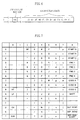
- Fig. 7 showing an ASCII-compatible bar code table in accordance with which the computer 1 generates required bar code data.
- this bar code table is provided with several characters which cannot be specified in the conventional ASCII code table. These special characters are arranged in unused areas of the conventional ASCII code table.
- Fig. 8 shows a control code generated in accordance with the ASCII-compatible bar code table of Fig. 7
- the first separation sign ("28") and the second separation sign ("29") are put in the ?1 section and the ?2 section, respectively, so that these two signs will be printed in the caption but not in the bar code.
- character codes are arranged.
- the character codes are included two codes "8D” and "8E” for specifying the separation signs placed in the ?1 and the ?2 sections, respectively.
- the control code of Fig. 8 includes a flag for indicating that this control code is an ASCII-compatible code.
- the CPU 21 of the printer 2 will deal with the ASCII-compatible control code of Fig. 8 in the same manner as with the EBCDIC-compatible control code of Fig. 4. To properly handle the ASCII-compatible control code, however, the CPU 21 first refers to the flag of the control code, to determine what code system the supplied control code is based on. Then, the CPU 21 switches to the ASCII-compatible code conversion table 24B from the EBCDIC-compatible code conversion table 24A. Thereafter, the control code of Fig. 8 is processed based on the conversion table 24B.
- the function of the conversion table 24B is substantially similar to that of the EBCDIC-compatible code conversion table 24A.
- the printer 2 of an embodiment of the present invention is provided with a plurality of code conversion tables compatible with different code standards.
- the printer 2 can properly process each control code in accordance with a selected one of the different code conversion tables.
- only one control code is needed to print a bar code and an accompanying caption in a non-one-to-one correspondence.
- the host computer does not need to switch between the text mode to print the bar code and the graphics mode to print the caption.
- it is possible to substantially reduce the load on the host computer and the amount of data to be dealt with for specifying the ID mark.
- the ID mark A (Fig. 1) includes a bar code A1, though the present invention is not limited to this.
- the bar code A1 may be replaced by a matrix-like symbol pattern.
- a printer cable for connecting the computer 1 to the printer 2.
- the computer 1 may be omitted, when the printer 2 is provided with equivalent functions necessary to input and process data about the ID mark to be printed.
Landscapes
- Physics & Mathematics (AREA)
- General Physics & Mathematics (AREA)
- Engineering & Computer Science (AREA)
- Theoretical Computer Science (AREA)
- Printers Characterized By Their Purpose (AREA)
- Record Information Processing For Printing (AREA)
- Discharge Of Articles From Conveyors (AREA)
- Radar Systems Or Details Thereof (AREA)
Abstract
Description
Claims (9)
- An identification mark output apparatus for outputting ID marks (A) each of which includes a symbol pattern (A1) and a caption (A2) accompanying the symbol pattern, the apparatus comprising:a data receiver (21) for receiving a single piece of mark-specifying information corresponding to a selected ID mark (A); andan output device (1, 2) for outputting the selected ID mark (A); characterized inthat the symbol pattern (A1) and the caption (A2) of the selected ID mark (A) are outputted in a non-one-to-one correspondence based on the single piece of mark-specifying information.
- The apparatus according to claim 1, wherein the output device (1, 2) is provided with code-converting means (24) for analyzing the contents of the single piece of mark-specifying information.
- The apparatus according to claim 2, wherein the code-converting means (24) comprises a plurality of code conversion tables (24A, 24B) corresponding to different code systems.
- The apparatus according to any one of claims 1-3, wherein the output device (1, 2) causes a separation sign of the selected ID mark (A) to be outputted in the caption (A2) but not in the symbol pattern (A1).
- The apparatus according to any one of claims 1-4, wherein the symbol pattern (A1) comprises a bar code.
- The apparatus according to any one of claims 1-5, wherein the single piece of mark-specifying information comprises character code data and separation sign data separate from the character code data.
- The apparatus according to any one of claims 1-5, wherein the single piece of mark-specifying information comprises character codes which include separation sign code and separation sign start code preceding the separation sign code.
- The apparatus according to any one of claims 1-7, wherein the single piece of mark-specifying information comprises a separation sign code for causing a predetermined separation sign to be outputted in any one of the bar code and the caption.
- The apparatus according to any one of claims 1-8, wherein the output device (1, 2) comprises a printer and/or a monitor.
Applications Claiming Priority (2)
| Application Number | Priority Date | Filing Date | Title |
|---|---|---|---|
| JP2000238037A JP3742285B2 (en) | 2000-08-07 | 2000-08-07 | Identification code output device |
| JP2000238037 | 2000-08-07 |
Publications (3)
| Publication Number | Publication Date |
|---|---|
| EP1179800A2 true EP1179800A2 (en) | 2002-02-13 |
| EP1179800A3 EP1179800A3 (en) | 2002-11-20 |
| EP1179800B1 EP1179800B1 (en) | 2009-02-18 |
Family
ID=18729803
Family Applications (1)
| Application Number | Title | Priority Date | Filing Date |
|---|---|---|---|
| EP20000311442 Expired - Lifetime EP1179800B1 (en) | 2000-08-07 | 2000-12-20 | Identification mark output apparatus |
Country Status (3)
| Country | Link |
|---|---|
| EP (1) | EP1179800B1 (en) |
| JP (1) | JP3742285B2 (en) |
| DE (1) | DE60041581D1 (en) |
Cited By (1)
| Publication number | Priority date | Publication date | Assignee | Title |
|---|---|---|---|---|
| US7690581B2 (en) | 2005-10-18 | 2010-04-06 | Seiko Epson Corporation | Method and apparatus for generating a barcode with a human readable interpretation, a printing apparatus, and a program |
Family Cites Families (3)
| Publication number | Priority date | Publication date | Assignee | Title |
|---|---|---|---|---|
| JP2979536B2 (en) * | 1992-06-08 | 1999-11-15 | ブラザー工業株式会社 | Barcode printing device |
| US5544287A (en) * | 1993-06-03 | 1996-08-06 | Monarch Marking Systems, Inc. | On-line barcode printer system with multi-level user printer commands |
| US6056195A (en) * | 1997-12-23 | 2000-05-02 | Spain; Wanda Hudgins | Method and apparatus for printing bar coded labels in different languages |
-
2000
- 2000-08-07 JP JP2000238037A patent/JP3742285B2/en not_active Expired - Fee Related
- 2000-12-20 EP EP20000311442 patent/EP1179800B1/en not_active Expired - Lifetime
- 2000-12-20 DE DE60041581T patent/DE60041581D1/en not_active Expired - Lifetime
Cited By (3)
| Publication number | Priority date | Publication date | Assignee | Title |
|---|---|---|---|---|
| US7690581B2 (en) | 2005-10-18 | 2010-04-06 | Seiko Epson Corporation | Method and apparatus for generating a barcode with a human readable interpretation, a printing apparatus, and a program |
| US20140263676A1 (en) * | 2005-10-18 | 2014-09-18 | Seiko Epson Corporation | Method and Apparatus for Generating a Barcode with a Human Readable Interpretation, a Printing Apparatus, and a Program |
| US9477919B2 (en) | 2005-10-18 | 2016-10-25 | Seiko Epson Corporation | Method and apparatus for generating a barcode with a human readable interpretation, a printing apparatus, and a program |
Also Published As
| Publication number | Publication date |
|---|---|
| JP3742285B2 (en) | 2006-02-01 |
| EP1179800B1 (en) | 2009-02-18 |
| JP2002052759A (en) | 2002-02-19 |
| DE60041581D1 (en) | 2009-04-02 |
| EP1179800A3 (en) | 2002-11-20 |
Similar Documents
| Publication | Publication Date | Title |
|---|---|---|
| US7185289B1 (en) | Device and method for changing languages on a display | |
| US5871293A (en) | Tape printer | |
| US7554679B2 (en) | Image forming apparatus, image forming method, and image forming program | |
| EP0843265B1 (en) | Character information processor | |
| US6633292B2 (en) | Recording device and recording method | |
| EP0440510A2 (en) | Layout display control system for document processing apparatus | |
| EP1179800B1 (en) | Identification mark output apparatus | |
| WO2002021306A2 (en) | Word processor with acronym facilator | |
| US5288155A (en) | Printer capable of displaying selected font | |
| EP1364771A1 (en) | Method of manufacturing rating label, and program for manufacturing rating label | |
| EP3224736B1 (en) | Label printer | |
| US6133899A (en) | Printing device for displaying a title of a stored text | |
| JP3692885B2 (en) | Message display device | |
| JPH02273267A (en) | Printer device | |
| JP7558554B2 (en) | Label issuing device | |
| JP3176988B2 (en) | Facsimile machine | |
| KR100238178B1 (en) | How to use application programs on your computer | |
| JPH10138571A (en) | Address writing printer | |
| US20190362176A1 (en) | Image processing device and image processing method | |
| JP2005141660A (en) | Printing apparatus and printing method | |
| KR20060057374A (en) | Mobile communication terminal equipped with an emoticon input function using a shortcut and its operation method | |
| JP2002366884A (en) | Apparatus and method for printing two-dimensional code | |
| JP2610180B2 (en) | Facsimile machine | |
| JPS634511B2 (en) | ||
| JP2005225172A (en) | Label printer |
Legal Events
| Date | Code | Title | Description |
|---|---|---|---|
| PUAI | Public reference made under article 153(3) epc to a published international application that has entered the european phase |
Free format text: ORIGINAL CODE: 0009012 |
|
| AK | Designated contracting states |
Kind code of ref document: A2 Designated state(s): AT BE CH CY DE DK ES FI FR GB GR IE IT LI LU MC NL PT SE TR |
|
| AX | Request for extension of the european patent |
Free format text: AL;LT;LV;MK;RO;SI |
|
| PUAL | Search report despatched |
Free format text: ORIGINAL CODE: 0009013 |
|
| AK | Designated contracting states |
Kind code of ref document: A3 Designated state(s): AT BE CH CY DE DK ES FI FR GB GR IE IT LI LU MC NL PT SE TR |
|
| AX | Request for extension of the european patent |
Free format text: AL;LT;LV;MK;RO;SI |
|
| 17P | Request for examination filed |
Effective date: 20030226 |
|
| RAP1 | Party data changed (applicant data changed or rights of an application transferred) |
Owner name: FUJI XEROX CO., LTD. |
|
| AKX | Designation fees paid |
Designated state(s): DE FR GB |
|
| GRAP | Despatch of communication of intention to grant a patent |
Free format text: ORIGINAL CODE: EPIDOSNIGR1 |
|
| GRAS | Grant fee paid |
Free format text: ORIGINAL CODE: EPIDOSNIGR3 |
|
| GRAA | (expected) grant |
Free format text: ORIGINAL CODE: 0009210 |
|
| AK | Designated contracting states |
Kind code of ref document: B1 Designated state(s): DE FR GB |
|
| REG | Reference to a national code |
Ref country code: GB Ref legal event code: FG4D |
|
| REF | Corresponds to: |
Ref document number: 60041581 Country of ref document: DE Date of ref document: 20090402 Kind code of ref document: P |
|
| PLBE | No opposition filed within time limit |
Free format text: ORIGINAL CODE: 0009261 |
|
| STAA | Information on the status of an ep patent application or granted ep patent |
Free format text: STATUS: NO OPPOSITION FILED WITHIN TIME LIMIT |
|
| 26N | No opposition filed |
Effective date: 20091119 |
|
| PGFP | Annual fee paid to national office [announced via postgrant information from national office to epo] |
Ref country code: GB Payment date: 20131218 Year of fee payment: 14 Ref country code: DE Payment date: 20131218 Year of fee payment: 14 |
|
| PGFP | Annual fee paid to national office [announced via postgrant information from national office to epo] |
Ref country code: FR Payment date: 20131209 Year of fee payment: 14 |
|
| REG | Reference to a national code |
Ref country code: DE Ref legal event code: R119 Ref document number: 60041581 Country of ref document: DE |
|
| GBPC | Gb: european patent ceased through non-payment of renewal fee |
Effective date: 20141220 |
|
| REG | Reference to a national code |
Ref country code: FR Ref legal event code: ST Effective date: 20150831 |
|
| PG25 | Lapsed in a contracting state [announced via postgrant information from national office to epo] |
Ref country code: DE Free format text: LAPSE BECAUSE OF NON-PAYMENT OF DUE FEES Effective date: 20150701 Ref country code: GB Free format text: LAPSE BECAUSE OF NON-PAYMENT OF DUE FEES Effective date: 20141220 |
|
| PG25 | Lapsed in a contracting state [announced via postgrant information from national office to epo] |
Ref country code: FR Free format text: LAPSE BECAUSE OF NON-PAYMENT OF DUE FEES Effective date: 20141231 |