EP1179670A1 - Method and device for driving an injector in an internal combustion engine - Google Patents
Method and device for driving an injector in an internal combustion engine Download PDFInfo
- Publication number
- EP1179670A1 EP1179670A1 EP01118659A EP01118659A EP1179670A1 EP 1179670 A1 EP1179670 A1 EP 1179670A1 EP 01118659 A EP01118659 A EP 01118659A EP 01118659 A EP01118659 A EP 01118659A EP 1179670 A1 EP1179670 A1 EP 1179670A1
- Authority
- EP
- European Patent Office
- Prior art keywords
- iinj
- injector
- voltage
- control circuit
- current intensity
- Prior art date
- Legal status (The legal status is an assumption and is not a legal conclusion. Google has not performed a legal analysis and makes no representation as to the accuracy of the status listed.)
- Granted
Links
- 238000000034 method Methods 0.000 title claims abstract description 31
- 238000002485 combustion reaction Methods 0.000 title claims abstract description 13
- 230000007423 decrease Effects 0.000 claims description 4
- 238000002347 injection Methods 0.000 description 42
- 239000007924 injection Substances 0.000 description 42
- 238000005259 measurement Methods 0.000 description 5
- 239000003054 catalyst Substances 0.000 description 3
- 239000000446 fuel Substances 0.000 description 2
- 230000001939 inductive effect Effects 0.000 description 2
- 238000011144 upstream manufacturing Methods 0.000 description 2
- 230000000694 effects Effects 0.000 description 1
- 231100001261 hazardous Toxicity 0.000 description 1
- 230000003071 parasitic effect Effects 0.000 description 1
- 230000000630 rising effect Effects 0.000 description 1
- 239000000243 solution Substances 0.000 description 1
- 230000003068 static effect Effects 0.000 description 1
- 238000012795 verification Methods 0.000 description 1
Images




Classifications
-
- F—MECHANICAL ENGINEERING; LIGHTING; HEATING; WEAPONS; BLASTING
- F02—COMBUSTION ENGINES; HOT-GAS OR COMBUSTION-PRODUCT ENGINE PLANTS
- F02D—CONTROLLING COMBUSTION ENGINES
- F02D41/00—Electrical control of supply of combustible mixture or its constituents
- F02D41/20—Output circuits, e.g. for controlling currents in command coils
-
- F—MECHANICAL ENGINEERING; LIGHTING; HEATING; WEAPONS; BLASTING
- F02—COMBUSTION ENGINES; HOT-GAS OR COMBUSTION-PRODUCT ENGINE PLANTS
- F02D—CONTROLLING COMBUSTION ENGINES
- F02D41/00—Electrical control of supply of combustible mixture or its constituents
- F02D41/20—Output circuits, e.g. for controlling currents in command coils
- F02D2041/2003—Output circuits, e.g. for controlling currents in command coils using means for creating a boost voltage, i.e. generation or use of a voltage higher than the battery voltage, e.g. to speed up injector opening
-
- F—MECHANICAL ENGINEERING; LIGHTING; HEATING; WEAPONS; BLASTING
- F02—COMBUSTION ENGINES; HOT-GAS OR COMBUSTION-PRODUCT ENGINE PLANTS
- F02D—CONTROLLING COMBUSTION ENGINES
- F02D41/00—Electrical control of supply of combustible mixture or its constituents
- F02D41/20—Output circuits, e.g. for controlling currents in command coils
- F02D2041/202—Output circuits, e.g. for controlling currents in command coils characterised by the control of the circuit
- F02D2041/2058—Output circuits, e.g. for controlling currents in command coils characterised by the control of the circuit using information of the actual current value
Definitions
- the present invention relates to a method for driving an injector in an internal combustion engine, and in particular for driving an injector of a direct petrol injection system, to which the following description will make explicit reference without, however, departing from its general nature.
- Petrol engines provided with direct fuel injection i.e. engines in which the petrol is injected directly into the cylinders by appropriate injectors, each of which is normally disposed in the port of a respective cylinder and is current-driven by a driving device, have recently been introduced into the market.
- Known driving devices are adapted to cause a current wave which is variable over time, which has an initial section substantially of a pulse type and having a relatively high current intensity, and a final section having a substantially constant and relatively low current intensity, to circulate via an injector control circuit.
- Known driving devices of the type described above are not able accurately to implement small injection times, i.e. having a very short final section (typical of the idling of the engine) because of the high energy stored in the inductive components of the control circuit of the injector during the above-mentioned initial section substantially of a pulse type and having a relatively high current intensity; this stored energy often prevents effective closure of the injector at the end of the final current section, and prolongs the opening of the injector for a certain time interval after the end of this final current section.
- the object of the present invention is to provide a method for driving an injector in an internal combustion engine which is free from the drawbacks described above and which is, moreover, simple and economic to embody.
- the present invention therefore relates to a method for driving an injector in an internal combustion engine as claimed in claim 1.
- the present invention further relates to a device for driving an injector in an internal combustion engine.
- the present invention therefore relates to a device for driving an injector in an internal combustion engine as claimed in claim 15.
- a device for the control of four injectors 2 of known type shown in Fig. 1 as INJECTOR1, INJECTOR2, INJECTOR3, INJECTOR 4
- an internal combustion engine 3 shown diagrammatically
- Each injector 2 is provided at the location of the port of a respective cylinder (not shown) of the engine 3 in order directly to inject a predetermined quantity of petrol into this cylinder.
- each injector 2 is current-driven and is provided with a control circuit 4 provided with a pair of terminals 5 and 6; in order to actuate an injector 2 it is necessary to cause an electric current of predetermined intensity to circulate through the respective control circuit 4.
- the control circuit 4 of each injector 2 comprises electrical components of inductive and of resistive type.
- the flow of petrol injected by each injector 2 during its opening phase is substantially constant and therefore the quantity of petrol injected by the injector 2 into the respective cylinder (not shown) is directly proportional to the opening time of this injector 2.
- the control device 1 is supplied by a battery 7 of the engine 3 and comprises a control unit 8, which is provided with a control member 9, a converter 10 supplied by the battery 7, a safety member 11 and a power stage 12.
- the control unit 9 dialogues with a control unit 13 (typically a microprocessor) of the engine 3 in order to receive the desired opening time value Tinj (directly proportional to the desired value of the quantity of fuel to be injected) and the injection start time from this control unit 13 for each injector 2 and for each engine cycle.
- the control member 9 controls the power stage 12 which actuates each injector 2 by causing a predetermined electric current Iinj (variable over time) to circulate through the respective control circuit 4 by applying a voltage Vinj (variable over time) to the heads of the corresponding terminals 5 and 6.
- the power stage 12 receives the control signals from the control member 9 and is supplied both directly from the battery 7 with a voltage Vbatt nominally equal to 12 Volt, and from the converter 10 with a voltage Vtank nominally equal to 80 Volt.
- the converter 10 is a d.c.-d.c. converter of known type which is able to raise the voltage Vbatt of the battery 7 to the voltage Vtank of 80V.
- the safety member 11 is able to dialogue with both the control member 9 and the power stage 12 so as to verify, using methods described below, the correct actuation of the injectors 2.
- the power stage 12 comprises, for each injector 2, a respective drive circuit 14 which is connected to the terminals 5 and 6 of the respective control circuit 4 and is controlled by the control member 9 in order to cause a predetermined electric current Iinj to circulate through this control circuit 4.
- Each drive circuit 14 comprises a transistor 15 controlled by the control member 9 and adapted to connect the terminal 5 of the respective control circuit 4 to an intermediate terminal 16 which is connected to the voltage Vbatt of the battery 7 via a non-return diode 17 and is connected to the voltage Vtank of the converter 10 via a transistor 18 controlled by the control member 9.
- Each drive circuit 14 further comprises a transistor 19 controlled by the control member 9 and adapted to connect the terminal 6 of the respective control circuit 4 to a common earth 20, and two recirculation diodes 20 and 22 connected respectively between the terminal 5 and the earth 20 and between the terminal 6 and the intermediate terminal 16.
- the transistors 15, 18, 19 are of MOS type.
- a shunt resistor 23 provided with a measurement terminal 24 is inserted between the transistor 19 and the earth 20; by measuring the voltage at the terminals of the resistor 23 (i.e. the voltage existing between the measurement terminal 24 and the earth 20) it is possible to measure the intensity of the current Iinj when the transistor 19 is conducting.
- the shunt resistor 23 is connected directly to the terminal 6 in order continuously to measure the intensity of the current Iinj.
- the shunt resistor 23 is connected upstream of the transistor 19 rather than downstream of the transistor 19 as shown in Fig. 2.
- an injection phase of an injector 2 is described below with particular reference to the time curve of the current Iinj circulating via the terminals 5 and 6 of the respective control circuit 4 and the time curve of the voltage Vinj at the heads of these terminals 5 and 6.
- the transistors 15, 18 and 19 are all deactivated, the control circuit 4 is isolated, the current Iinj has a zero value and the injector is closed.
- the transistors 15, 18 and 19 are simultaneously caused to conduct, then the terminal 5 is connected to the voltage Vtank via the transistors 15 and 18, the terminal 6 is connected to the earth 20 via the transistor 19 and the voltage Vinj is equal to Vtank.
- the current Iinj increases rapidly for a time T1 up to a peak value Ip and the injector 2 opens and starts to inject petrol.
- a current control (which uses the measurement of the current Iinj performed using the resistor 23) maintains the current Iinj within an amplitude range ⁇ Ip centred on a mean value Ipm for a time T2 by acting on the control of the transistor 19 which switches cyclically between a conducting state and a deactivated state.
- the terminal 5 is connected to the voltage Vtank via the transistors 15 and 18, the terminal 6 is connected to the earth 20 via the transistor 19, the voltage Vinj is equal to Vtank and the value of Iinj increases; whereas during the deactivated state of the transistor 19, the recirculation diode 22 starts to conduct and short-circuits the terminals 5 and 6 via the transistor 15, the voltage Vinj is zero and the value of Iinj decreases.
- the intensity of the current Iinj is measured only when the transistor 19 is conducting, since the measurement resistor 23 is disposed upstream of the transistor 19; however, the time constant of the control circuit 4 is known and constant, and therefore the control member 9 is able to calculate when the current Iinj reaches the lower limit (Ipm- ⁇ Ip/2) and the transistor 19 must be caused to conduct again.
- the control member 9 causes the transistors 15 and 19 to continue to conduct and deactivates the transistor 18, and therefore the terminal 5 is connected to the voltage Vbatt via the transistor 15 and the diode 17, the terminal 6 is connected to the earth 20 via the transistor 19 and the voltage Vinj is equal to Vbatt.
- the current Iinj drops slowly for a predetermined time T3 to a value IpF; at this point the control member 9 simultaneously deactivates all three transistors 15, 18 and 19 and, as a result of the current Iinj that cannot be instantaneously cancelled out, the recirculation diode 21 and, in an inverse manner, the transistor 18 start to conduct, with the result that the terminal 5 is connected to the earth 20 via the recirculation diode 21, the terminal 6 is connected to the voltage Vtank via the recirculation diode 22 and the transistor 18, the voltage Vinj is equal to -Vtank and the current Iinj decreases rapidly.
- the transistor 18 starts to conduct in an inverse manner as a result of the characteristics of the MOS junction, which has a parasitic diode disposed in parallel with this junction and adapted to be biased in an inverse manner with respect to the junction.
- the control member 9 brings to and maintains the current Iinj substantially at a value Im causing the transistor 15 to continue to conduct and acting on the control of the transistor 19 which switches cyclically between a conducting state and a deactivated state.
- the transistor 19 is current-driven to maintain the current Iinj within an amplitude range ⁇ Im centred on Im for a time T5 according to the methods described above.
- all the transistors 15, 18 and 19 are deactivated and the current Iinj rapidly returns to zero according to the methods described above.
- the injector 2 closes and stops injecting petrol.
- the sum of the times T1, T2, T3, T4, T5 is equal to the total injection time Tinj, i.e. to the total time during which the injector 2 remains open.
- the control circuit 4 is traversed by a current wave which is variable over time and comprises an initial section (corresponding to the time intervals T1, T2 and T3) which is substantially of a pulse type and has a relatively high current intensity Iinj equal to the peak value Ip, an intermediate section (corresponding to the time interval T4) during which the current intensity Iinj is rapidly reduced to substantially zero values and a subsequent final section (corresponding to the time interval T5) which has a relatively low current intensity Iinj equal to a value Im.
- the initial section of the current wave Iinj comprises a first part (corresponding to the time interval T1), in which the intensity of the current Iinj increases rapidly to the value Ip, a second part (corresponding to the time interval T2), in which the intensity of the current Iinj is maintained substantially constant and equal to the value Ip, and a third part (corresponding to the time interval T3) in which the intensity of the current Iinj progressively diminishes.
- the initial section of pulse type is characterised by a rapid increase of the intensity of the current Iinj to high values and is necessary to ensure rapid opening of the injector 2; in order rapidly to open the injector 2 a high force (proportional to the square of the current intensity Iinj) is needed so that mechanical inertia and both static and dynamic friction can be rapidly overcome.
- a high force proportional to the square of the current intensity Iinj
- the injector 2 needs a relatively low force to remain open and therefore during the final phase the current Iinj is maintained at the relatively low value Im.
- the current is cancelled out for an extremely short period which is not sufficient to allow the injector 2 to close again as a result of the system's mechanical inertia; the current Iinj needs to be cancelled out to discharge the energy accumulated during the initial phase in the inductances of the control circuit 4.
- the injector 2 closes again exactly at the end of the time T5 and does not remain open for a longer time as a result of the energy stored in the inductances during the initial phase.
- the current Iinj is maintained substantially constant (less a tolerance equal to ⁇ Ip/2 and ⁇ Im/2) during the time intervals T2 and T5 using a "chopper" technique, i.e. by applying a positive voltage (Vtank or Vbatt) and a zero voltage cyclically to the heads of the control circuit 4 (i.e. between the terminals 5 and 6).
- Vtank or Vbatt a positive voltage
- Vbatt zero voltage
- the first part (corresponding to the time interval T1) of the above-mentioned initial section of the current wave Iinj comprises an initial portion (corresponding to the time interval T1a) in which the current Iinj is maintained substantially constant and equal to a contained value (generally lower, and in particular equal to approximately half of the value Im) using a "chopper" technique (known and described above), and a final portion (corresponding to the time interval T1b) in which the current Iinj is caused rapidly to rise to relatively high values (of the order of magnitude of double the value Ipm) by applying the voltage Vtank uninterruptedly to the heads of the control circuit 4 (i.e. between the terminals 5 and 6).
- the voltage Vbatt of the battery 7 is equal to 12V, while the voltage Vtank of the converter 10 has a nominal value preferably of between 60 and 90V; moreover, the actual value of the voltage Vtank of the converter 10 may decrease with respect to the initial nominal value during the driving of an injector 2 as a result of the load effect due to the respective control circuit 4.
- the control unit 13 requests a verification of the actual injection times Tinjeff of the injectors 2 from the safety member 11, so as to check whether each injector 2 is injecting exactly (less a certain tolerance obviously) the quantity of petrol calculated by the control unit 13 on the basis of commands received from a driver and on the basis of the operating conditions of the engine 3 into the respective cylinder (not shown).
- This check is extremely important as in direct petrol injection engines the torque generated depends directly on the quantity of petrol injected (and therefore on the actual injection time Tinjeff) and an incorrect driving of the injectors 2 may cause the engine 3 to generate a drive torque which is much higher than the drive torque desired by the driver which would obviously be hazardous for the driver.
- the control unit 13 sends a request to the safety member 11 together with the desired injection time values Tinj for each injector 2 in the subsequent engine cycle; the safety member then measures in sequence the actual injection times Tinjeff of all the injectors 2 and, once these measurements have been completed, compares each actual injection time value Tinjeff with the respective desired injection time value Tinj which has been calculated previously by the control unit 13.
- the control member 11 decides whether or not to generate an error signal.
- the error signal is generated if, for one injector 2 at least, the difference between the desired injection time value Tinj and the actual injection time value Tinjeff is outside a predetermined acceptability range.
- the error signal is generated on the basis of a combination of the results of the comparisons between the actual injection time values Tinjeff and the desired injection time values Tinj of all the injectors 2.
- the actual injection time Tinjeff of an injector 2 is calculated both by detecting the intensity of the current Iinj passing through the respective control circuit 4 and by detecting the control signal of the respective transistor 15 (as the main transistor of the relative drive circuit 14). According to a further embodiment, the actual injection time Tinjeff of an injector 2 is calculated either by detecting the intensity of the current Iinj passing through the respective control circuit 4 or by detecting the control signal of the respective transistor 15. According to a further embodiment, the actual injection time Tinjeff of an injector 2 is calculated both by detecting the intensity of the current Iinj passing through the respective control circuit 4 and by detecting the control signal of all the transistors 15, 18 and 19 of the relative drive circuit 14.
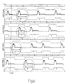
- Fig. 4 shows, for each injector 2, an example of the wave shape of the intensity of the current Iinj and of the control signal of the respective transistor 15 during a control cycle performed by the safety member 11.
- the control unit 13 sends the request to perform a control cycle to the safety member 11; at this point, the safety member 11 disregards the injection pulses already under way (INJECTOR1 and INJECTOR4) and measures the actual injection time Tinjeff for each injector 2 during the subsequent injection pulses.
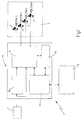
- a drive circuit 14 is adapted to drive two injectors 2 (for instance, as shown in Fig. 5, INJECTOR1 and INJECTOR4) using two transistors 19 (shown in Fig. 5 by 19a and 19b and associated with INJECTOR1 and INJECTOR4 respectively), each of which connects a respective terminal 6 to the earth 20.
- two transistors 19 shown in Fig. 5 by 19a and 19b and associated with INJECTOR1 and INJECTOR4 respectively
- the operation of the drive circuit 14 of Fig. 5 is completely identical to the above-described operation of the drive circuit 14 of Fig.2; obviously, the transistor 19a is controlled to open the injector INJECTOR1, while the transistor 19b is controlled to open the injector INJECTOR4.
- the drive circuit 14 shown in Fig. 5 also makes it possible to carry out a secondary injection of the other injector (INJECTOR4); as is known, this secondary injection is adapted to regenerate a catalyst device (known and not shown) disposed on an exhaust (not shown) of the engine 3 by desulphurising this catalyst device by means of the temperature increase due to the combustion in the catalyst device of the petrol injected with the secondary injection.
- a catalyst device known and not shown
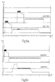
- the secondary injection of an injector is carried out simply by causing the relative transistor 19 (19b for INJECTOR4) to conduct; according to further embodiments, the secondary injection may be carried out by keeping the transistor 18 constantly deactivated (Fig. 6b) or by causing the transistor 18 to conduct (Fig. 6a).
- the difference between the two solutions lies in the fact that in one case (transistor 18 constantly deactivated), the current wave Iinj of the secondary injection has a gentler pulse (and therefore slower and less accurate opening) as it is generated by a voltage Vinj equal to Vbatt and, in the other case (transistor 18 initially caused to conduct), the current wave Iinj of the secondary injection has a much steeper pulse as it is generated by a voltage Vinj equal to Vtank.
- the current Iinj of the main injection does not suffer variations of intensity with respect to the preceding regime as the transistor 19 is current controlled; when the transistor 18 is caused to conduct, the steepness of the rising edge of the current Iinj increases as a result of the increased driving voltage and the current control increases the rapidity of switching in order always to maintain the current Iinj within the range ⁇ Im, centred on Im.
- the above-described intermediate section of cancelling out of the current Iinj by deactivating the transistors 15, 18 and 19b can also be carried out for the secondary injection (INJECTOR4); in this case the current Iinj of the main injection (INJECTOR1) suffers a momentary, but not particularly high, downturn as the transistor 19a of the main injection (INJECTOR1) continues to conduct.
- the power stage 12 is formed as modules (not shown); in particular it comprises a first module provided with the transistors 15 and 18 and the diodes 17 and 20 and a second module provided with the transistor 19, the diode 21 and the resistor 23.
- a first and a second module are connected together, while in order to provide a drive circuit 14 of the type shown in Fig. 5 for the control of two injectors 2, a first and a pair of second modules are connected together.
Landscapes
- Engineering & Computer Science (AREA)
- Chemical & Material Sciences (AREA)
- Combustion & Propulsion (AREA)
- Mechanical Engineering (AREA)
- General Engineering & Computer Science (AREA)
- Electrical Control Of Air Or Fuel Supplied To Internal-Combustion Engine (AREA)
- Fuel-Injection Apparatus (AREA)
Abstract
Description
- The present invention relates to a method for driving an injector in an internal combustion engine, and in particular for driving an injector of a direct petrol injection system, to which the following description will make explicit reference without, however, departing from its general nature.
- Petrol engines provided with direct fuel injection, i.e. engines in which the petrol is injected directly into the cylinders by appropriate injectors, each of which is normally disposed in the port of a respective cylinder and is current-driven by a driving device, have recently been introduced into the market.
- Known driving devices are adapted to cause a current wave which is variable over time, which has an initial section substantially of a pulse type and having a relatively high current intensity, and a final section having a substantially constant and relatively low current intensity, to circulate via an injector control circuit.
- Known driving devices of the type described above are not able accurately to implement small injection times, i.e. having a very short final section (typical of the idling of the engine) because of the high energy stored in the inductive components of the control circuit of the injector during the above-mentioned initial section substantially of a pulse type and having a relatively high current intensity; this stored energy often prevents effective closure of the injector at the end of the final current section, and prolongs the opening of the injector for a certain time interval after the end of this final current section.
- The object of the present invention is to provide a method for driving an injector in an internal combustion engine which is free from the drawbacks described above and which is, moreover, simple and economic to embody.
- The present invention therefore relates to a method for driving an injector in an internal combustion engine as claimed in
claim 1. - The present invention further relates to a device for driving an injector in an internal combustion engine.
- The present invention therefore relates to a device for driving an injector in an internal combustion engine as claimed in
claim 15. - The present invention will now be described with reference to the accompanying drawings, which show some non-limiting embodiments thereof, in which:
- Fig. 1 is a diagrammatic view of the control device of the present invention;
- Fig. 2 is a diagrammatic view of an actuation circuit of the control device of Fig. 1;
- Fig. 3 shows the time curve of some electrical magnitudes characteristic of the circuit of Fig. 2;
- Fig. 4 shows the time curve of some electrical magnitudes characteristic of the device of Fig. 1;
- Fig. 5 is a diagrammatic view of a variant of the actuation circuit of Fig. 2;
- Fig. 6 shows the time curve of some electrical magnitudes characteristic of the circuit of Fig. 5;
- Fig. 7 shows the time curve of some electrical magnitudes characteristic of the circuit of Fig. 2 in a different embodiment alternative to that of Fig. 3.
-
- In Fig. 1, a device for the control of four
injectors 2 of known type (shown in Fig. 1 as INJECTOR1, INJECTOR2, INJECTOR3, INJECTOR 4) of an internal combustion engine 3 (shown diagrammatically) provided with four cylinders (not shown) disposed in line is shown overall by 1. Eachinjector 2 is provided at the location of the port of a respective cylinder (not shown) of theengine 3 in order directly to inject a predetermined quantity of petrol into this cylinder. - As shown in Fig. 2, each
injector 2 is current-driven and is provided with acontrol circuit 4 provided with a pair ofterminals 5 and 6; in order to actuate aninjector 2 it is necessary to cause an electric current of predetermined intensity to circulate through therespective control circuit 4. It has been observed in experimental tests that thecontrol circuit 4 of eachinjector 2 comprises electrical components of inductive and of resistive type. The flow of petrol injected by eachinjector 2 during its opening phase is substantially constant and therefore the quantity of petrol injected by theinjector 2 into the respective cylinder (not shown) is directly proportional to the opening time of thisinjector 2. - The
control device 1 is supplied by abattery 7 of theengine 3 and comprises acontrol unit 8, which is provided with acontrol member 9, aconverter 10 supplied by thebattery 7, asafety member 11 and apower stage 12. - The
control unit 9 dialogues with a control unit 13 (typically a microprocessor) of theengine 3 in order to receive the desired opening time value Tinj (directly proportional to the desired value of the quantity of fuel to be injected) and the injection start time from thiscontrol unit 13 for eachinjector 2 and for each engine cycle. On the basis of the data received from thecontrol unit 13, thecontrol member 9 controls thepower stage 12 which actuates eachinjector 2 by causing a predetermined electric current Iinj (variable over time) to circulate through therespective control circuit 4 by applying a voltage Vinj (variable over time) to the heads of thecorresponding terminals 5 and 6. - The
power stage 12 receives the control signals from thecontrol member 9 and is supplied both directly from thebattery 7 with a voltage Vbatt nominally equal to 12 Volt, and from theconverter 10 with a voltage Vtank nominally equal to 80 Volt. Theconverter 10 is a d.c.-d.c. converter of known type which is able to raise the voltage Vbatt of thebattery 7 to the voltage Vtank of 80V. - The
safety member 11 is able to dialogue with both thecontrol member 9 and thepower stage 12 so as to verify, using methods described below, the correct actuation of theinjectors 2. - As shown in Fig. 2, the
power stage 12 comprises, for eachinjector 2, arespective drive circuit 14 which is connected to theterminals 5 and 6 of therespective control circuit 4 and is controlled by thecontrol member 9 in order to cause a predetermined electric current Iinj to circulate through thiscontrol circuit 4. - Each
drive circuit 14 comprises atransistor 15 controlled by thecontrol member 9 and adapted to connect theterminal 5 of therespective control circuit 4 to anintermediate terminal 16 which is connected to the voltage Vbatt of thebattery 7 via anon-return diode 17 and is connected to the voltage Vtank of theconverter 10 via atransistor 18 controlled by thecontrol member 9. Eachdrive circuit 14 further comprises atransistor 19 controlled by thecontrol member 9 and adapted to connect the terminal 6 of therespective control circuit 4 to acommon earth 20, and tworecirculation diodes terminal 5 and theearth 20 and between the terminal 6 and theintermediate terminal 16. According to a preferred embodiment shown in Fig. 2, thetransistors - A
shunt resistor 23 provided with ameasurement terminal 24 is inserted between thetransistor 19 and theearth 20; by measuring the voltage at the terminals of the resistor 23 (i.e. the voltage existing between themeasurement terminal 24 and the earth 20) it is possible to measure the intensity of the current Iinj when thetransistor 19 is conducting. According to a further embodiment (not shown), theshunt resistor 23 is connected directly to the terminal 6 in order continuously to measure the intensity of the current Iinj. According to a further embodiment (not shown), theshunt resistor 23 is connected upstream of thetransistor 19 rather than downstream of thetransistor 19 as shown in Fig. 2. - As shown in Figs. 2 and 3, an injection phase of an
injector 2 is described below with particular reference to the time curve of the current Iinj circulating via theterminals 5 and 6 of therespective control circuit 4 and the time curve of the voltage Vinj at the heads of theseterminals 5 and 6. - Initially, the
transistors control circuit 4 is isolated, the current Iinj has a zero value and the injector is closed. - To start the injection phase, the
transistors terminal 5 is connected to the voltage Vtank via thetransistors earth 20 via thetransistor 19 and the voltage Vinj is equal to Vtank. In these conditions, the current Iinj increases rapidly for a time T1 up to a peak value Ip and theinjector 2 opens and starts to inject petrol. - When the current Iinj reaches the value Ip, a current control (which uses the measurement of the current Iinj performed using the resistor 23) maintains the current Iinj within an amplitude range ΔIp centred on a mean value Ipm for a time T2 by acting on the control of the
transistor 19 which switches cyclically between a conducting state and a deactivated state. During the conducting state of thetransistor 19, theterminal 5 is connected to the voltage Vtank via thetransistors earth 20 via thetransistor 19, the voltage Vinj is equal to Vtank and the value of Iinj increases; whereas during the deactivated state of thetransistor 19, therecirculation diode 22 starts to conduct and short-circuits theterminals 5 and 6 via thetransistor 15, the voltage Vinj is zero and the value of Iinj decreases. The intensity of the current Iinj is measured only when thetransistor 19 is conducting, since themeasurement resistor 23 is disposed upstream of thetransistor 19; however, the time constant of thecontrol circuit 4 is known and constant, and therefore thecontrol member 9 is able to calculate when the current Iinj reaches the lower limit (Ipm-ΔIp/2) and thetransistor 19 must be caused to conduct again. - After the current Iinj has remained substantially at the value Ip for the time T2, the
control member 9 causes thetransistors transistor 18, and therefore theterminal 5 is connected to the voltage Vbatt via thetransistor 15 and thediode 17, the terminal 6 is connected to theearth 20 via thetransistor 19 and the voltage Vinj is equal to Vbatt. In these circumstances, the current Iinj drops slowly for a predetermined time T3 to a value IpF; at this point thecontrol member 9 simultaneously deactivates all threetransistors recirculation diode 21 and, in an inverse manner, thetransistor 18 start to conduct, with the result that theterminal 5 is connected to theearth 20 via therecirculation diode 21, the terminal 6 is connected to the voltage Vtank via therecirculation diode 22 and thetransistor 18, the voltage Vinj is equal to -Vtank and the current Iinj decreases rapidly. - It should be noted that the
transistor 18 starts to conduct in an inverse manner as a result of the characteristics of the MOS junction, which has a parasitic diode disposed in parallel with this junction and adapted to be biased in an inverse manner with respect to the junction. - After a time T4 sufficient substantially to cancel out the current Iinj, the
control member 9 brings to and maintains the current Iinj substantially at a value Im causing thetransistor 15 to continue to conduct and acting on the control of thetransistor 19 which switches cyclically between a conducting state and a deactivated state. In this situation, thetransistor 19 is current-driven to maintain the current Iinj within an amplitude range ΔIm centred on Im for a time T5 according to the methods described above. At the end of the time T5, all thetransistors - Once the current Iinj returns to zero and remains at a zero value for a predetermined time, the
injector 2 closes and stops injecting petrol. As clearly shown in Fig. 3, the sum of the times T1, T2, T3, T4, T5 is equal to the total injection time Tinj, i.e. to the total time during which theinjector 2 remains open. - It will be appreciated from the above that during the injection phase, the
control circuit 4 is traversed by a current wave which is variable over time and comprises an initial section (corresponding to the time intervals T1, T2 and T3) which is substantially of a pulse type and has a relatively high current intensity Iinj equal to the peak value Ip, an intermediate section (corresponding to the time interval T4) during which the current intensity Iinj is rapidly reduced to substantially zero values and a subsequent final section (corresponding to the time interval T5) which has a relatively low current intensity Iinj equal to a value Im. - The initial section of the current wave Iinj comprises a first part (corresponding to the time interval T1), in which the intensity of the current Iinj increases rapidly to the value Ip, a second part (corresponding to the time interval T2), in which the intensity of the current Iinj is maintained substantially constant and equal to the value Ip, and a third part (corresponding to the time interval T3) in which the intensity of the current Iinj progressively diminishes.
- The initial section of pulse type is characterised by a rapid increase of the intensity of the current Iinj to high values and is necessary to ensure rapid opening of the
injector 2; in order rapidly to open the injector 2 a high force (proportional to the square of the current intensity Iinj) is needed so that mechanical inertia and both static and dynamic friction can be rapidly overcome. Once open, theinjector 2 needs a relatively low force to remain open and therefore during the final phase the current Iinj is maintained at the relatively low value Im. - During the intermediate phase, the current is cancelled out for an extremely short period which is not sufficient to allow the
injector 2 to close again as a result of the system's mechanical inertia; the current Iinj needs to be cancelled out to discharge the energy accumulated during the initial phase in the inductances of thecontrol circuit 4. In this way, even when the time T5 is extremely low, i.e. when the total injection time Tinj is small (typically during idling), theinjector 2 closes again exactly at the end of the time T5 and does not remain open for a longer time as a result of the energy stored in the inductances during the initial phase. - It will be appreciated from the above that the current Iinj is maintained substantially constant (less a tolerance equal to ΔIp/2 and ΔIm/2) during the time intervals T2 and T5 using a "chopper" technique, i.e. by applying a positive voltage (Vtank or Vbatt) and a zero voltage cyclically to the heads of the control circuit 4 (i.e. between the
terminals 5 and 6). This control technique has major advantages as it makes it possible extremely accurately to maintain the desired current value (Ip or Im) and at the same time to reduce overall dissipation losses to a minimum. - According to a different embodiment shown in Fig. 7 (which shows the time curves of the current Iinj circulating through the
terminals 5 and 6 of therespective control circuit 4 and the time curve of the voltage Vinj at the heads of theseterminals 5 and 6), the first part (corresponding to the time interval T1) of the above-mentioned initial section of the current wave Iinj comprises an initial portion (corresponding to the time interval T1a) in which the current Iinj is maintained substantially constant and equal to a contained value (generally lower, and in particular equal to approximately half of the value Im) using a "chopper" technique (known and described above), and a final portion (corresponding to the time interval T1b) in which the current Iinj is caused rapidly to rise to relatively high values (of the order of magnitude of double the value Ipm) by applying the voltage Vtank uninterruptedly to the heads of the control circuit 4 (i.e. between theterminals 5 and 6). - It should be noted that the voltage Vbatt of the
battery 7 is equal to 12V, while the voltage Vtank of theconverter 10 has a nominal value preferably of between 60 and 90V; moreover, the actual value of the voltage Vtank of theconverter 10 may decrease with respect to the initial nominal value during the driving of aninjector 2 as a result of the load effect due to therespective control circuit 4. - Cyclically, the
control unit 13 requests a verification of the actual injection times Tinjeff of theinjectors 2 from thesafety member 11, so as to check whether eachinjector 2 is injecting exactly (less a certain tolerance obviously) the quantity of petrol calculated by thecontrol unit 13 on the basis of commands received from a driver and on the basis of the operating conditions of theengine 3 into the respective cylinder (not shown). This check is extremely important as in direct petrol injection engines the torque generated depends directly on the quantity of petrol injected (and therefore on the actual injection time Tinjeff) and an incorrect driving of theinjectors 2 may cause theengine 3 to generate a drive torque which is much higher than the drive torque desired by the driver which would obviously be hazardous for the driver. - In order to conduct a check of compliance with the desired injection times Tinj, the
control unit 13 sends a request to thesafety member 11 together with the desired injection time values Tinj for eachinjector 2 in the subsequent engine cycle; the safety member then measures in sequence the actual injection times Tinjeff of all theinjectors 2 and, once these measurements have been completed, compares each actual injection time value Tinjeff with the respective desired injection time value Tinj which has been calculated previously by thecontrol unit 13. - Depending on the result of the comparison between each actual injection time value Tinjeff and the respective desired injection time value Tinj, the
control member 11 decides whether or not to generate an error signal. According to a preferred embodiment, the error signal is generated if, for oneinjector 2 at least, the difference between the desired injection time value Tinj and the actual injection time value Tinjeff is outside a predetermined acceptability range. According to a further embodiment, the error signal is generated on the basis of a combination of the results of the comparisons between the actual injection time values Tinjeff and the desired injection time values Tinj of all theinjectors 2. - According to a preferred embodiment, the actual injection time Tinjeff of an
injector 2 is calculated both by detecting the intensity of the current Iinj passing through therespective control circuit 4 and by detecting the control signal of the respective transistor 15 (as the main transistor of the relative drive circuit 14). According to a further embodiment, the actual injection time Tinjeff of aninjector 2 is calculated either by detecting the intensity of the current Iinj passing through therespective control circuit 4 or by detecting the control signal of therespective transistor 15. According to a further embodiment, the actual injection time Tinjeff of aninjector 2 is calculated both by detecting the intensity of the current Iinj passing through therespective control circuit 4 and by detecting the control signal of all thetransistors relative drive circuit 14. - Fig. 4 shows, for each
injector 2, an example of the wave shape of the intensity of the current Iinj and of the control signal of therespective transistor 15 during a control cycle performed by thesafety member 11. At the moment Tstart, thecontrol unit 13 sends the request to perform a control cycle to thesafety member 11; at this point, thesafety member 11 disregards the injection pulses already under way (INJECTOR1 and INJECTOR4) and measures the actual injection time Tinjeff for eachinjector 2 during the subsequent injection pulses. - According to a further embodiment shown in Fig. 5, a
drive circuit 14 is adapted to drive two injectors 2 (for instance, as shown in Fig. 5, INJECTOR1 and INJECTOR4) using two transistors 19 (shown in Fig. 5 by 19a and 19b and associated with INJECTOR1 and INJECTOR4 respectively), each of which connects a respective terminal 6 to theearth 20. In this way, it is possible to use a smaller number of overall components as thetransistors drive circuit 14 are shared by thecontrol circuits 4 of twodifferent injectors 2. - The operation of the
drive circuit 14 of Fig. 5 is completely identical to the above-described operation of thedrive circuit 14 of Fig.2; obviously, thetransistor 19a is controlled to open the injector INJECTOR1, while thetransistor 19b is controlled to open the injector INJECTOR4. - During the main injection phase of an injector (for instance INJECTOR1), the
drive circuit 14 shown in Fig. 5 also makes it possible to carry out a secondary injection of the other injector (INJECTOR4); as is known, this secondary injection is adapted to regenerate a catalyst device (known and not shown) disposed on an exhaust (not shown) of theengine 3 by desulphurising this catalyst device by means of the temperature increase due to the combustion in the catalyst device of the petrol injected with the secondary injection. - The secondary injection of an injector (for instance INJECTOR4) is carried out simply by causing the relative transistor 19 (19b for INJECTOR4) to conduct; according to further embodiments, the secondary injection may be carried out by keeping the
transistor 18 constantly deactivated (Fig. 6b) or by causing thetransistor 18 to conduct (Fig. 6a). The difference between the two solutions lies in the fact that in one case (transistor 18 constantly deactivated), the current wave Iinj of the secondary injection has a gentler pulse (and therefore slower and less accurate opening) as it is generated by a voltage Vinj equal to Vbatt and, in the other case (transistor 18 initially caused to conduct), the current wave Iinj of the secondary injection has a much steeper pulse as it is generated by a voltage Vinj equal to Vtank. - As shown in Fig. 6a, even when the
transistor 18 is caused to conduct to initiate the secondary injection (INJECTOR4), the current Iinj of the main injection (INJECTOR1) does not suffer variations of intensity with respect to the preceding regime as thetransistor 19 is current controlled; when thetransistor 18 is caused to conduct, the steepness of the rising edge of the current Iinj increases as a result of the increased driving voltage and the current control increases the rapidity of switching in order always to maintain the current Iinj within the range ΔIm, centred on Im. - Lastly, as shown in Fig. 6a, the above-described intermediate section of cancelling out of the current Iinj by deactivating the
transistors transistor 19a of the main injection (INJECTOR1) continues to conduct. - According to a preferred embodiment, the
power stage 12 is formed as modules (not shown); in particular it comprises a first module provided with thetransistors diodes transistor 19, thediode 21 and theresistor 23. In order to provide adrive circuit 14 of the type shown in Fig. 2 for controlling asingle injector 2, a first and a second module are connected together, while in order to provide adrive circuit 14 of the type shown in Fig. 5 for the control of twoinjectors 2, a first and a pair of second modules are connected together.
Claims (20)
- A method for driving an injector (2) in an internal combustion engine (3), in which method a current wave (Iinj) which is variable over time, which comprises an initial section (T1, T2, T3) having a relatively high current intensity (Iinj) and a subsequent final section (T5) having a relatively low current intensity (Iinj), is caused to circulate through a control circuit (4) of the injector (2), the method being characterised in that the current wave (Iinj) comprises an intermediate section (T4) between the first and second sections (T1, T2, T3; T5) during which the current intensity (Iinj) is rapidly reduced to substantially zero values.
- A method as claimed in claim 1, in which the initial section (T1, T2, T3) is substantially a pulse section.
- A method as claimed in claim 1 or 2, in which the current intensity (Iinj) is maintained substantially constant and equal to a first predetermined value (Im) during the final section (T5).
- A method as claimed in claim 3, in which the current intensity (Iinj) is maintained substantially constant and equal to a second predetermined value (Ip) greater than the first value (Im) during at least part of the initial section (T1, T2, T3).
- A method as claimed in claim 4, in which the initial section (T1, T2, T3) comprises a first part (T1) in which the current intensity (Iinj) rises rapidly towards the second predetermined value (Ip), a second part (T2) in which the current intensity (Iinj) is maintained substantially constant and equal to the second predetermined value (Ip) and a third part (T3) in which the current intensity (Iinj) progressively decreases.
- A method as claimed in claim 3, 4 or 5, in which the current intensity (Iinj) is maintained substantially constant and equal to a predetermined value (Ip; Im) by applying a first and a second voltage value, different from one another, cyclically to the control circuit (4) of the injector (2).
- A method as claimed in claim 6, in which the second voltage value is equal to zero.
- A method as claimed in claim 6 or 7, in which the choice of switching between the first and the second voltage value is carried out by means of a closed-loop control of the value of the current intensity (Iinj) so as to maintain the value of the current intensity (Iinj) within a range (ΔIp; ΔIm) centred on the predetermined value (Ip; Im).
- A method as claimed in one of the preceding claims, in which the control circuit (4) of the injector (2) is driven by means of a first voltage (Vtank) during the initial section (T1, T2, T3) and the control circuit (4) of the injector (2) is driven by a second voltage (Vbatt), which is equal to the battery voltage and is lower than the first voltage (Vtank), during the final section (T5).
- A method as claimed in claim 9, in which the first voltage (Vtank) is generated by a d.c-d.c. converter from the battery voltage.
- A method as claimed in claim 9 or 10, in which the first voltage (Vtank) is between 60 and 90V, while the second voltage (Vbatt) is substantially equal to 12V.
- A method as claimed in one of the preceding claims, in which a positive voltage and a zero voltage are alternately applied to the control circuit (4) during the initial and final sections (T1, T2, T3, T5), and a negative voltage is applied to the control circuit (4) during the intermediate section (T4).
- A method for driving an injector (2) in an internal combustion engine (3), in which method a current wave (Iinj) which is variable over time, which comprises an initial section (T1, T2, T3) having a relatively high current intensity (Iinj) and a subsequent final section (T5) having a relatively low current intensity (Iinj) is caused to circulate through a control circuit (4) of the injector (2), the method being characterised in that the during the initial section (T1, T2, T3) the control circuit (4) of the injector (4) is driven by a first voltage (Vtank) and during the final section (T5) the control circuit (4) of the injector (2) is driven by a second voltage (Vbatt) which is equal to the battery voltage and is lower than the first voltage (Vtank).
- A method for driving an injector (2) in an internal combustion engine (3), in which method a current wave (Iinj) which is variable over time, which comprises an initial section (T1, T2, T3) having a relatively high current intensity (Iinj) and a subsequent final section (T5) having a relatively low current intensity (Iinj) is caused to circulate through a control circuit (4) of the injector (2), the method being characterised in that the current intensity (Iinj) is maintained substantially constant by applying a first and a second voltage value, different from one another, cyclically to the control circuit (4) of the injector (2).
- A device for driving an injector (2) in an internal combustion engine (3), the injector (2) comprising a control circuit (4) provided with a first and a second terminal (5; 6) and the device (1) comprising an actuator circuit (14) adapted to cause a current wave (Iinj) which is variable over time, which comprises an initial section (T1, T2, T3) having a relatively high current intensity (Iinj) and a subsequent final section (T5) having a relatively low current intensity (Iinj) to circulate through a control circuit (4) of the injector (2), the device being characterised in that the actuator circuit (14) comprises first transistor means (15, 18) for connecting the first terminal (5) to a voltage generator (7; 10), second transistor means (19) for connecting the second terminal (6) to an earth (20) of the voltage generator (7; 10) and recirculation diodes (21; 22) enabling the discharge of the inductances of the control circuit (4).
- A device as claimed in claim 15, in which the first transistor means (15) comprise a pair of transistors (15, 18) for selectively connecting the first terminal (5) to a first and a second voltage generator (7; 10).
- A device as claimed in claim 16, in which a first recirculation diode (21) connects the first terminal (5) to the earth (20) and a second recirculation diode (22) connects the second terminal (6) to the voltage generator (7; 10).
- A device as claimed in claim 15, 16 or 17, in which the transistors (15, 18, 19) are of MOS type.
- A device as claimed in one of claims 15 to 18, and adapted also to drive a further injector (2) comprising a respective control circuit (4) provided with a first and a second terminal (5; 6), the first terminal (5) of the further injector (2) being connected to the first terminal (5) of the injector (2) and the actuator circuit (4) comprising second transistor means (19b) for connecting the terminal (6) of the further injector (2) to the earth (20).
- A device as claimed in one of claims 15 to 19, in which the actuator circuit (14) is formed by connecting at least two modules, the first of which comprises the first transistor means (15; 18) and the second of which comprises the second transistor means (19).
Priority Applications (1)
| Application Number | Priority Date | Filing Date | Title |
|---|---|---|---|
| EP04017769A EP1473453B1 (en) | 2000-08-04 | 2001-08-02 | Device for driving an injector in an internal combustion engine |
Applications Claiming Priority (3)
| Application Number | Priority Date | Filing Date | Title |
|---|---|---|---|
| IT2000BO000489A ITBO20000489A1 (en) | 2000-08-04 | 2000-08-04 | METHOD AND DEVICE FOR PILOTING AN INJECTOR IN AN INTERNAL COMBUSTION ENGINE. |
| ITBO20000489 | 2000-08-04 | ||
| ITBO000489 | 2000-08-04 |
Related Child Applications (1)
| Application Number | Title | Priority Date | Filing Date |
|---|---|---|---|
| EP04017769A Division EP1473453B1 (en) | 2000-08-04 | 2001-08-02 | Device for driving an injector in an internal combustion engine |
Publications (2)
| Publication Number | Publication Date |
|---|---|
| EP1179670A1 true EP1179670A1 (en) | 2002-02-13 |
| EP1179670B1 EP1179670B1 (en) | 2005-03-16 |
Family
ID=11438679
Family Applications (2)
| Application Number | Title | Priority Date | Filing Date |
|---|---|---|---|
| EP04017769A Expired - Lifetime EP1473453B1 (en) | 2000-08-04 | 2001-08-02 | Device for driving an injector in an internal combustion engine |
| EP01118659A Expired - Lifetime EP1179670B1 (en) | 2000-08-04 | 2001-08-02 | Method and device for driving an injector in an internal combustion engine |
Family Applications Before (1)
| Application Number | Title | Priority Date | Filing Date |
|---|---|---|---|
| EP04017769A Expired - Lifetime EP1473453B1 (en) | 2000-08-04 | 2001-08-02 | Device for driving an injector in an internal combustion engine |
Country Status (6)
| Country | Link |
|---|---|
| US (1) | US6584961B2 (en) |
| EP (2) | EP1473453B1 (en) |
| BR (1) | BR0104306A (en) |
| DE (2) | DE60120795T2 (en) |
| ES (2) | ES2264783T3 (en) |
| IT (1) | ITBO20000489A1 (en) |
Cited By (6)
| Publication number | Priority date | Publication date | Assignee | Title |
|---|---|---|---|---|
| WO2004016926A1 (en) * | 2002-07-26 | 2004-02-26 | Robert Bosch Gmbh | Method for controlling and/or regulating a constant voltage converter for at least two electromagnetic valves of an internal combustion engine, especially an internal combustion engine in a motor vehicle |
| WO2009077254A1 (en) * | 2007-12-17 | 2009-06-25 | Robert Bosch Gmbh | Method for operating an injection device |
| EP2077384A1 (en) | 2008-01-07 | 2009-07-08 | Hitachi Ltd. | Fuel injection control apparatus |
| CN102628405A (en) * | 2011-02-02 | 2012-08-08 | 日立汽车系统株式会社 | Injector drive circuit |
| EP2365202A3 (en) * | 2010-03-09 | 2012-09-05 | Hitachi Automotive Systems, Ltd. | Electromagnetic valve driving circuit |
| WO2015124304A1 (en) * | 2014-02-20 | 2015-08-27 | Man Diesel & Turbo Se | Control unit of an internal combustion engine |
Families Citing this family (14)
| Publication number | Priority date | Publication date | Assignee | Title |
|---|---|---|---|---|
| US20050279780A1 (en) * | 2004-04-30 | 2005-12-22 | Howard Evans | Switch mode gun driver and method |
| JP4561321B2 (en) * | 2004-11-09 | 2010-10-13 | サンケン電気株式会社 | Solenoid drive |
| US7013876B1 (en) | 2005-03-31 | 2006-03-21 | Caterpillar Inc. | Fuel injector control system |
| DE102007003211A1 (en) * | 2007-01-22 | 2008-07-24 | Robert Bosch Gmbh | Device and method for controlling an electromagnetic valve |
| JP2008291778A (en) * | 2007-05-25 | 2008-12-04 | Denso Corp | Solenoid valve control device |
| JP2010255444A (en) * | 2009-04-21 | 2010-11-11 | Hitachi Automotive Systems Ltd | Fuel injection control device and method for internal combustion engine |
| US9611797B2 (en) * | 2012-10-30 | 2017-04-04 | National Instruments Corporation | Direct injection flexible multiplexing scheme |
| JP5772788B2 (en) | 2012-11-05 | 2015-09-02 | 株式会社デンソー | Fuel injection control device and fuel injection system |
| DE102013203130A1 (en) * | 2013-02-26 | 2014-08-28 | Robert Bosch Gmbh | Method for controlling an injection process of a magnet injector |
| JP6717176B2 (en) | 2016-12-07 | 2020-07-01 | 株式会社デンソー | Injection control device |
| FR3065089B1 (en) * | 2017-04-11 | 2019-06-28 | Schneider Electric Industries Sas | METHOD FOR CONTROLLING AN ELECTRIC CURRENT CUTTING APPARATUS, ELECTROMAGNETIC ACTUATOR COMPRISING A CIRCUIT FOR CARRYING OUT SAID METHOD, AND ELECTRIC CUTTING APPARATUS COMPRISING SUCH ACTUATOR |
| JP6844501B2 (en) | 2017-10-31 | 2021-03-17 | 株式会社デンソー | Fuel injection valve control device and fuel injection valve control method |
| CN113586303B (en) * | 2021-08-23 | 2022-07-19 | 一汽解放汽车有限公司 | Oil injection time determining system and vehicle |
| CN115986166B (en) * | 2023-01-04 | 2026-04-24 | 一汽解放汽车有限公司 | Hydrogen injection control method, apparatus, computer equipment and storage medium |
Citations (3)
| Publication number | Priority date | Publication date | Assignee | Title |
|---|---|---|---|---|
| DE4411789A1 (en) * | 1994-04-06 | 1995-10-12 | Bosch Gmbh Robert | Control of fuel metering for IC engine |
| US5532526A (en) * | 1991-12-23 | 1996-07-02 | Elasis Sistema Ricerca Fiat Nel Mezzogiorno Societa Consortile Per Azioni | Control circuit for predominantly inductive loads in particular electroinjectors |
| DE19746981A1 (en) * | 1997-10-24 | 1999-04-29 | Bosch Gmbh Robert | Method of driving electromagnetic load, esp. a magnetic fuel injection valve for an internal combustion engine |
Family Cites Families (21)
| Publication number | Priority date | Publication date | Assignee | Title |
|---|---|---|---|---|
| JPS5675956A (en) * | 1979-11-27 | 1981-06-23 | Nippon Denso Co Ltd | Injector driving circuit |
| US4479161A (en) * | 1982-09-27 | 1984-10-23 | The Bendix Corporation | Switching type driver circuit for fuel injector |
| US4486703A (en) * | 1982-09-27 | 1984-12-04 | The Bendix Corporation | Boost voltage generator |
| US4631628A (en) * | 1983-06-08 | 1986-12-23 | Chrysler Motors Corporation | Electronic fuel injector driver circuit |
| US4604675A (en) * | 1985-07-16 | 1986-08-05 | Caterpillar Tractor Co. | Fuel injection solenoid driver circuit |
| US4764840A (en) * | 1986-09-26 | 1988-08-16 | Motorola, Inc. | Dual limit solenoid driver control circuit |
| IT1218673B (en) * | 1987-08-25 | 1990-04-19 | Marelli Autronica | CIRCUIT FOR THE CONTROL OF INDUCTIVE LOADS IN PARTICULAR FOR THE CONTROL OF THE ELECTROINJECTORS OF A DIESEL CYCLE ENGINE |
| IT1217171B (en) * | 1987-08-25 | 1990-03-14 | Marelli Autronica | CIRCUIT FOR THE DRIVING OF INDUCTIVE LOADS IN PARTICULAR FOR THE CONTROL OF THE ELECTROINJECTORS OF A DIESEL CYCLE INTERNAL COMBUSTION ENGINE |
| US4862866A (en) * | 1987-08-25 | 1989-09-05 | Marelli Autronica S.P.A. | Circuit for the piloting of inductive loads, particularly for operating the electro-injectors of a diesel-cycle internal combustion engine |
| US4905120A (en) * | 1988-10-20 | 1990-02-27 | Caterpillar Inc. | Driver circuit for solenoid operated fuel injectors |
| IT1223872B (en) * | 1988-10-27 | 1990-09-29 | Marelli Autronica | CIRCUIT FOR PILOTING AN INDUCTIVE LOAD IN PARTICULAR FOR THE CONTROL OF THE ELECTROINJECTORS OF A DIESEL CYCLE ENGINE |
| US5053911A (en) * | 1989-06-02 | 1991-10-01 | Motorola, Inc. | Solenoid closure detection |
| US5430601A (en) * | 1993-04-30 | 1995-07-04 | Chrysler Corporation | Electronic fuel injector driver circuit |
| US5381297A (en) * | 1993-06-18 | 1995-01-10 | Siemens Automotive L.P. | System and method for operating high speed solenoid actuated devices |
| US5469825A (en) * | 1994-09-19 | 1995-11-28 | Chrysler Corporation | Fuel injector failure detection circuit |
| WO1996027198A1 (en) * | 1995-03-02 | 1996-09-06 | Robert Bosch Gmbh | Device for controlling at least one electromagnetic consumer |
| US5812355A (en) * | 1995-09-25 | 1998-09-22 | Nordson Corporation | Electric gun driver |
| US5788154A (en) * | 1996-05-02 | 1998-08-04 | Caterpillar Inc. | Method of preventing cavitation in a fuel injector having a solenoid actuated control valve |
| GB9619786D0 (en) * | 1996-09-20 | 1996-11-06 | Lucas Ind Plc | Drive circuit |
| US5752482A (en) * | 1997-03-28 | 1998-05-19 | Cummins Engine Company, Inc. | System for integrally controlling current flow through number of inductive loads |
| DE19732854B4 (en) * | 1997-07-30 | 2006-04-20 | Mitsubishi Denki K.K. | Control device for controlling a fuel injection device of an internal combustion engine |
-
2000
- 2000-08-04 IT IT2000BO000489A patent/ITBO20000489A1/en unknown
-
2001
- 2001-08-02 ES ES04017769T patent/ES2264783T3/en not_active Expired - Lifetime
- 2001-08-02 EP EP04017769A patent/EP1473453B1/en not_active Expired - Lifetime
- 2001-08-02 EP EP01118659A patent/EP1179670B1/en not_active Expired - Lifetime
- 2001-08-02 DE DE60120795T patent/DE60120795T2/en not_active Expired - Lifetime
- 2001-08-02 DE DE60109371T patent/DE60109371T2/en not_active Expired - Lifetime
- 2001-08-02 ES ES01118659T patent/ES2238367T3/en not_active Expired - Lifetime
- 2001-08-03 BR BR0104306-4A patent/BR0104306A/en not_active Application Discontinuation
- 2001-08-03 US US09/922,397 patent/US6584961B2/en not_active Expired - Fee Related
Patent Citations (3)
| Publication number | Priority date | Publication date | Assignee | Title |
|---|---|---|---|---|
| US5532526A (en) * | 1991-12-23 | 1996-07-02 | Elasis Sistema Ricerca Fiat Nel Mezzogiorno Societa Consortile Per Azioni | Control circuit for predominantly inductive loads in particular electroinjectors |
| DE4411789A1 (en) * | 1994-04-06 | 1995-10-12 | Bosch Gmbh Robert | Control of fuel metering for IC engine |
| DE19746981A1 (en) * | 1997-10-24 | 1999-04-29 | Bosch Gmbh Robert | Method of driving electromagnetic load, esp. a magnetic fuel injection valve for an internal combustion engine |
Cited By (13)
| Publication number | Priority date | Publication date | Assignee | Title |
|---|---|---|---|---|
| WO2004016926A1 (en) * | 2002-07-26 | 2004-02-26 | Robert Bosch Gmbh | Method for controlling and/or regulating a constant voltage converter for at least two electromagnetic valves of an internal combustion engine, especially an internal combustion engine in a motor vehicle |
| WO2009077254A1 (en) * | 2007-12-17 | 2009-06-25 | Robert Bosch Gmbh | Method for operating an injection device |
| EP2077384A1 (en) | 2008-01-07 | 2009-07-08 | Hitachi Ltd. | Fuel injection control apparatus |
| US7789073B2 (en) | 2008-01-07 | 2010-09-07 | Hitachi, Ltd. | Fuel injection control apparatus |
| EP2365202A3 (en) * | 2010-03-09 | 2012-09-05 | Hitachi Automotive Systems, Ltd. | Electromagnetic valve driving circuit |
| US8599530B2 (en) | 2010-03-09 | 2013-12-03 | Hitachi Automotive Systems, Ltd. | Electromagnetic valve driving circuit |
| EP2492478A1 (en) * | 2011-02-02 | 2012-08-29 | Hitachi Automotive Systems, Ltd. | Injector drive circuit |
| CN102628405A (en) * | 2011-02-02 | 2012-08-08 | 日立汽车系统株式会社 | Injector drive circuit |
| US8649151B2 (en) | 2011-02-02 | 2014-02-11 | Hitachi Automotive Systems, Ltd. | Injector drive circuit |
| CN102628405B (en) * | 2011-02-02 | 2014-11-19 | 日立汽车系统株式会社 | Injector drive circuit |
| WO2015124304A1 (en) * | 2014-02-20 | 2015-08-27 | Man Diesel & Turbo Se | Control unit of an internal combustion engine |
| CN105992868A (en) * | 2014-02-20 | 2016-10-05 | 曼柴油机和涡轮机欧洲股份公司 | Controllers for internal combustion engines |
| US10167807B2 (en) | 2014-02-20 | 2019-01-01 | Man Energy Solutions Se | Control unit of an internal combustion engine |
Also Published As
| Publication number | Publication date |
|---|---|
| DE60109371D1 (en) | 2005-04-21 |
| EP1473453B1 (en) | 2006-06-14 |
| DE60120795D1 (en) | 2006-07-27 |
| DE60120795T2 (en) | 2007-05-24 |
| EP1179670B1 (en) | 2005-03-16 |
| ES2238367T3 (en) | 2005-09-01 |
| EP1473453A3 (en) | 2004-11-10 |
| ITBO20000489A1 (en) | 2002-02-04 |
| DE60109371T2 (en) | 2006-04-06 |
| US20020014223A1 (en) | 2002-02-07 |
| EP1473453A2 (en) | 2004-11-03 |
| BR0104306A (en) | 2002-04-02 |
| US6584961B2 (en) | 2003-07-01 |
| ITBO20000489A0 (en) | 2000-08-04 |
| ES2264783T3 (en) | 2007-01-16 |
Similar Documents
| Publication | Publication Date | Title |
|---|---|---|
| US6584961B2 (en) | Method and device for driving an injector in an internal combustion engine | |
| JP4776651B2 (en) | Internal combustion engine control device | |
| US9376982B2 (en) | Control apparatus for fuel injector | |
| US20170226950A1 (en) | Fuel injection control device for internal combustion engine | |
| EP1065677A2 (en) | Electromagnetic load control apparatus having variable drive-starting energy supply | |
| US5383086A (en) | System and method for triggering an inductive consumer | |
| US7117852B2 (en) | Single device for controlling fuel electro-injectors and electrovalves in an internal-combustion engine, and method of operating the same | |
| US7124741B2 (en) | Method for controlling an injector with verification that plunger movement has occurred | |
| EP1903201B1 (en) | Valve control strategy and controller | |
| US8989994B2 (en) | System and method for fault diagnosis in fuel injection system | |
| US8108126B2 (en) | Method of controlling fuel injection apparatus | |
| EP1179669B1 (en) | Method for the control of an injector in an internal combustion engine | |
| US11421620B2 (en) | Injection control device | |
| WO2019087899A1 (en) | Fuel injection valve control device and fuel injection valve control method | |
| JP2013137028A (en) | Device and method for fuel injection control of internal combustion engine | |
| JP2005201245A (en) | Control device for electric actuator for detecting end of operation and method for detecting end of operation of electric actuator | |
| JP2002295293A (en) | Fuel injection device | |
| JP4089092B2 (en) | Injector control device | |
| US11326537B2 (en) | Injection control device | |
| EP1138906B1 (en) | Optimization of injection systems having piezoelectric elements by compensating for temperature dependence | |
| JP2005163549A (en) | Injector drive device | |
| JPH11200931A (en) | Solenoid valve drive |
Legal Events
| Date | Code | Title | Description |
|---|---|---|---|
| PUAI | Public reference made under article 153(3) epc to a published international application that has entered the european phase |
Free format text: ORIGINAL CODE: 0009012 |
|
| AK | Designated contracting states |
Kind code of ref document: A1 Designated state(s): DE ES FR GB SE Kind code of ref document: A1 Designated state(s): AT BE CH CY DE DK ES FI FR GB GR IE IT LI LU MC NL PT SE TR |
|
| AX | Request for extension of the european patent |
Free format text: AL;LT;LV;MK;RO;SI |
|
| 17P | Request for examination filed |
Effective date: 20020807 |
|
| AKX | Designation fees paid |
Free format text: DE ES FR GB SE |
|
| 17Q | First examination report despatched |
Effective date: 20040414 |
|
| GRAP | Despatch of communication of intention to grant a patent |
Free format text: ORIGINAL CODE: EPIDOSNIGR1 |
|
| GRAS | Grant fee paid |
Free format text: ORIGINAL CODE: EPIDOSNIGR3 |
|
| GRAA | (expected) grant |
Free format text: ORIGINAL CODE: 0009210 |
|
| RAP1 | Party data changed (applicant data changed or rights of an application transferred) |
Owner name: MAGNETI MARELLI POWERTRAIN S.P.A. |
|
| AK | Designated contracting states |
Kind code of ref document: B1 Designated state(s): DE ES FR GB SE |
|
| REG | Reference to a national code |
Ref country code: GB Ref legal event code: FG4D |
|
| REG | Reference to a national code |
Ref country code: IE Ref legal event code: FG4D |
|
| REF | Corresponds to: |
Ref document number: 60109371 Country of ref document: DE Date of ref document: 20050421 Kind code of ref document: P |
|
| REG | Reference to a national code |
Ref country code: SE Ref legal event code: TRGR |
|
| REG | Reference to a national code |
Ref country code: ES Ref legal event code: FG2A Ref document number: 2238367 Country of ref document: ES Kind code of ref document: T3 |
|
| PLBE | No opposition filed within time limit |
Free format text: ORIGINAL CODE: 0009261 |
|
| STAA | Information on the status of an ep patent application or granted ep patent |
Free format text: STATUS: NO OPPOSITION FILED WITHIN TIME LIMIT |
|
| ET | Fr: translation filed | ||
| 26N | No opposition filed |
Effective date: 20051219 |
|
| PGFP | Annual fee paid to national office [announced via postgrant information from national office to epo] |
Ref country code: ES Payment date: 20090811 Year of fee payment: 9 |
|
| PGFP | Annual fee paid to national office [announced via postgrant information from national office to epo] |
Ref country code: GB Payment date: 20090728 Year of fee payment: 9 Ref country code: SE Payment date: 20090727 Year of fee payment: 9 |
|
| EUG | Se: european patent has lapsed | ||
| GBPC | Gb: european patent ceased through non-payment of renewal fee |
Effective date: 20100802 |
|
| PG25 | Lapsed in a contracting state [announced via postgrant information from national office to epo] |
Ref country code: GB Free format text: LAPSE BECAUSE OF NON-PAYMENT OF DUE FEES Effective date: 20100802 |
|
| REG | Reference to a national code |
Ref country code: ES Ref legal event code: FD2A Effective date: 20111019 |
|
| PG25 | Lapsed in a contracting state [announced via postgrant information from national office to epo] |
Ref country code: ES Free format text: LAPSE BECAUSE OF NON-PAYMENT OF DUE FEES Effective date: 20100803 |
|
| PG25 | Lapsed in a contracting state [announced via postgrant information from national office to epo] |
Ref country code: SE Free format text: LAPSE BECAUSE OF NON-PAYMENT OF DUE FEES Effective date: 20100803 |
|
| PGFP | Annual fee paid to national office [announced via postgrant information from national office to epo] |
Ref country code: DE Payment date: 20140722 Year of fee payment: 14 |
|
| PGFP | Annual fee paid to national office [announced via postgrant information from national office to epo] |
Ref country code: FR Payment date: 20140822 Year of fee payment: 14 |
|
| REG | Reference to a national code |
Ref country code: DE Ref legal event code: R119 Ref document number: 60109371 Country of ref document: DE |
|
| REG | Reference to a national code |
Ref country code: FR Ref legal event code: ST Effective date: 20160429 |
|
| PG25 | Lapsed in a contracting state [announced via postgrant information from national office to epo] |
Ref country code: DE Free format text: LAPSE BECAUSE OF NON-PAYMENT OF DUE FEES Effective date: 20160301 |
|
| PG25 | Lapsed in a contracting state [announced via postgrant information from national office to epo] |
Ref country code: FR Free format text: LAPSE BECAUSE OF NON-PAYMENT OF DUE FEES Effective date: 20150831 |