EP1179478A2 - Strapping machine - Google Patents
Strapping machine Download PDFInfo
- Publication number
- EP1179478A2 EP1179478A2 EP01304946A EP01304946A EP1179478A2 EP 1179478 A2 EP1179478 A2 EP 1179478A2 EP 01304946 A EP01304946 A EP 01304946A EP 01304946 A EP01304946 A EP 01304946A EP 1179478 A2 EP1179478 A2 EP 1179478A2
- Authority
- EP
- European Patent Office
- Prior art keywords
- cover
- strap path
- strapping machine
- strap
- path
- Prior art date
- Legal status (The legal status is an assumption and is not a legal conclusion. Google has not performed a legal analysis and makes no representation as to the accuracy of the status listed.)
- Granted
Links
- 230000001681 protective effect Effects 0.000 claims description 5
- 238000004140 cleaning Methods 0.000 abstract description 4
- 239000000463 material Substances 0.000 description 8
- 238000000034 method Methods 0.000 description 5
- 238000012423 maintenance Methods 0.000 description 4
- 239000000470 constituent Substances 0.000 description 2
- 230000000712 assembly Effects 0.000 description 1
- 238000000429 assembly Methods 0.000 description 1
- 238000005266 casting Methods 0.000 description 1
- 230000001934 delay Effects 0.000 description 1
- 230000000994 depressogenic effect Effects 0.000 description 1
- 238000006073 displacement reaction Methods 0.000 description 1
- 238000003780 insertion Methods 0.000 description 1
- 230000037431 insertion Effects 0.000 description 1
- 238000005461 lubrication Methods 0.000 description 1
- 238000003754 machining Methods 0.000 description 1
Images
Classifications
-
- B—PERFORMING OPERATIONS; TRANSPORTING
- B65—CONVEYING; PACKING; STORING; HANDLING THIN OR FILAMENTARY MATERIAL
- B65B—MACHINES, APPARATUS OR DEVICES FOR, OR METHODS OF, PACKAGING ARTICLES OR MATERIALS; UNPACKING
- B65B13/00—Bundling articles
- B65B13/18—Details of, or auxiliary devices used in, bundling machines or bundling tools
-
- B—PERFORMING OPERATIONS; TRANSPORTING
- B65—CONVEYING; PACKING; STORING; HANDLING THIN OR FILAMENTARY MATERIAL
- B65B—MACHINES, APPARATUS OR DEVICES FOR, OR METHODS OF, PACKAGING ARTICLES OR MATERIALS; UNPACKING
- B65B13/00—Bundling articles
- B65B13/18—Details of, or auxiliary devices used in, bundling machines or bundling tools
- B65B13/184—Strap accumulators
-
- B—PERFORMING OPERATIONS; TRANSPORTING
- B65—CONVEYING; PACKING; STORING; HANDLING THIN OR FILAMENTARY MATERIAL
- B65B—MACHINES, APPARATUS OR DEVICES FOR, OR METHODS OF, PACKAGING ARTICLES OR MATERIALS; UNPACKING
- B65B2210/00—Specific aspects of the packaging machine
- B65B2210/12—Means for automatically detecting and removing jammed straps in strapping machines, e.g. jam clearing devices
Definitions
- Strapping machines are complex assemblies of parts which combine to move strap material from a reel to a head where the material is placed about an object to be strapped. Because of the complexity of these strapping machines, the debris which is produced in the strapping process, and the speed with which the strapping material may travel though the machine, access to the strap path for maintenance and cleaning is often required.
- US-A-5746882 discloses one arrangement in which a strap path door is configured for pivotal movement to permit access to the various components within the strap path (e.g., the strapping head).
- the access door is mounted directly to a structural member (i.e., the strapping head) and as such it requires that a hinge collar or collars be formed as part of the structure of the strapping head. Because this part of the strapping head structure is a cast or otherwise costly (e.g., highly machined) component, the hinge assembly is, likewise a costly assembly.
- a strapping machine allowing easy access to a strap path.
- the strapping machine comprises a head defining a strap path and a cover, pivotally attached to the strapping machine.
- the cover is attached such that in a first closed position the cover comprises a protective exterior element of the strapping machine and provides the outer guiding constituent for the strap path elements, and in a second, pivoted open position, the cover allows access to the strap path.
- the strap path cover is hinged to an outer, non-structural panel of the strapping machine housing and may be rotated down so as to allow access to the strap path.
- the hinge used to mount the door to the machine need not be a cast or like highly machined or engineered part. Rather, the hinge can be made from relatively common components, such as a piano hinge or the like.
- the strap path cover further provides the outer elements of a number of the strap path components. As the cover is hinged, it is easily rotated down to expose parts of the strap path and then rotated back to its initial position to align the outer elements of the strap path constituents so that the strapping process may resume.
- the strapping machine of the present invention further comprises an upper strap guide having an upper guide strap cover that is hinged and may be pivoted down to clear the strap path defined therein. The upper guide cover, in its first default position, provides elements of the upper strap path.
- the strap path cover defines a number of openings through which such elements as feed wheel axles, strap gate and winder parts and alignment pins may protrude.
- the outer feed wheel guides, the outer winder wall and the strap gate guide may be formed by the interior wall of the strap path cover.
- the strap path cover may then be pivoted down from the strap path, dividing elements of the feed wheels, winder and strap gate so that strapping material or debris may be removed from the path and from within those strap path elements. Further, maintenance on strap path elements may be done while the strap path cover is in an open position.
- the upper path guide may also be pivoted, independently from the strap path cover, to allow access to the upper strap path for clearing of debris and jams.
- the upper guide defines openings for upper path elements and alignment pins allowing the path to be returned to alignment by pivoting the guide back to its first position.
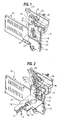
- Figure 1 shows a strapping machine 10 having a strap path accumulator door 12, in a first position, rotatably connected to the strapping machine 10 by a hinge 14, and a pivotal locking element or lever 16.
- Door 12 defines a number of openings 18 through which portions of elements such as feed wheel axle 20, winder end 22 and strap gate element 24 may protrude. Further, door 12 defines alignment openings 19 through which alignment pins 26 ( Figures 2, 3 and 4) may protrude.
- the interior wall 13 ( Figure 2) of accumulator door 12 when rotated to a closed position, comprises end elements for various strap path components. The end elements so defined provide guidance, or a path, for strapping material flowing through head 11 of strapping machine 10.
- An upper strap guide cover 28 is also shown in Figure 1 and will be explained in greater detail below.
- the door 12 is mounted to a non-structural portion of the strapping machine 10.
- the door is mounted to the take-up box cover 15.
- the present non-structural mounting arrangement e.g., to the take-up box door 15 of the door 12 permits the use of less costly, commonly available hinges, such as the illustrated piano hinge 14.
- the more costly cast-in-place and or machined hinges provided the necessary alignment of the access door 12 over the strapping head, by the skilled assembly of the hinge in conjunction with the relatively small tolerances of casting and/or machining.
- the present access door 12 likewise provides this necessary alignment over the head 11 by the use of alignment pins 26 extending outwardly from the head 11 that engage or extend into openings 19 in the door.
- Figure 2 shows the strapping machine of Figure 1, having strap path accumulator door 12 in an open, strap path accessible, position. It may be seen that lever 16 has been pivoted down to release door 12 so that it may be rotated down on hinge 14. With door 12 open, it can be seen, particularly in Figures 2, 3 and 4, that such elements as the feed wheels 30, winder 32 and strap gate 34 ( Figures 1 and 2) are exposed by the removal of door 12. Any debris or strapping material is easily removed while those elements are uncovered such that the interior of the strap path through those elements is exposed.
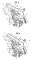
- an upper strap guide 28 is provided covering one of the take up wheels 36 and the upper strap path 38.
- Strap path guide 28 is hinged so that it may be pivoted down ( Figure 4) to expose the strap path 38 through take-up wheel 36.
- strap guide 28 defines a number of openings including an opening 40 for a spring (not shown) and openings 42a and 42b for aligning pins 44a and 44b, respectively, and a slot 46 through which a rim of take up wheel 36 may protrude. Openings 42a and 42b provide a means for properly aligning guide 28 such that the strap path defined by take up wheel 36 and guide 28 may operate properly.
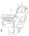
- Figure 5 reveals a floating strap guide 50 moveably attached to the strap accumulator door 12 by a loose pin 52, a screw 54 and washer 56.
- a fixed strap guide 58 is attached to head 11 by tapered alignment pins 26, and creates, in association with floating strap guide 50, an integral part of the strap path. Alignment openings 19, in floating guide 50, position floating guide 50 in correct alignment with fixed guide 58.
- Floating guide 50 as a result of its relatively loose attachment to door 12 is free to align itself on tapered alignment pins 26, when door 12 is returned to its first, operating position.
- the ability of guide 50 to float and align itself on alignment pins 26 assures accurate positioning of the floating guide 50 upon the closing of door 12, such that the strap path is properly formed.
- strapping machine 10 In the operation of strapping machine 10, when it is found that a jam has occurred or when a scheduled cleaning is due, strapping machine 10 may be stopped and lever 16 may be depressed to open door 12. Strap path accumulator door 12 may then be rotated down, on hinge 14, revealing the strap path of strapping machine 10. The rotation down of door 12 causes the removal of end elements, which are part of door 12, of various strap path components and thus, allows access to the strap path. Access to the strap path allows the user to clear debris and loose strap from the strap path and allows for general maintenance, replacement of worn parts and lubrication of the elements of the strap path. When the strap path has been cleared and/or the elements of the strap path have been replaced, maintained or lubricated, door 12 may be pivoted up and locked back into place by lever 16.
- the elements of the strap path formed on door 12 and mounted on door 12 are returned aligned with the fixed parts of the strap path. Alignment is assured by engagement (insertion) of the pins 26 with or through the openings 19.
- the tapered configuration or shape of the pins 26 facilitates proper centering of the openings 19 over the pins 26 as the door 12 is pivoted or rotated closed. The strapping process may be resumed immediately upon the closing of door 12. Clearance and maintenance of upper strap guide 28, may also be accomplished in a similar manner with similar results.
- hinged door 12 which provides end elements of the strap path, also provides access to the accumulator box (not shown) of strapping machine 10, to allow for clearing of excess strapping material and the clearing of any jams that have developed in strapping machine 10.
Landscapes
- Engineering & Computer Science (AREA)
- Mechanical Engineering (AREA)
- Basic Packing Technique (AREA)
- Details Of Cutting Devices (AREA)
Abstract
Description
- Strapping machines are complex assemblies of parts which combine to move strap material from a reel to a head where the material is placed about an object to be strapped. Because of the complexity of these strapping machines, the debris which is produced in the strapping process, and the speed with which the strapping material may travel though the machine, access to the strap path for maintenance and cleaning is often required.
- In strap machines used presently, access to the strap path has generally been achieved through the difficult disassembly of housing panels and removal or displacement of key strap path components. The machine may then be cleared of strap debris and jams. The components must then be carefully aligned and reassembled prior to resuming strapping. Such a disassembly and reassembly is generally required at each incident of jamming of the strapping machine and the strapping machine may need to be cleaned of debris often, depending on the material used in the strapping process and the amount of strapping being done. Poor alignment of the strap path components may lead to further jams and more disassembly of the strapping machine. In general, due to the complexities of the strapping machines, assembly and disassembly has been very time consuming and exacting, forcing great delays in the strapping process.
- US-A-5746882 discloses one arrangement in which a strap path door is configured for pivotal movement to permit access to the various components within the strap path (e.g., the strapping head). Although this access path apparatus works well for its intended purpose, the access door is mounted directly to a structural member (i.e., the strapping head) and as such it requires that a hinge collar or collars be formed as part of the structure of the strapping head. Because this part of the strapping head structure is a cast or otherwise costly (e.g., highly machined) component, the hinge assembly is, likewise a costly assembly.
- It would be preferable to have a strapping machine where the strap path may be accessed and cleared without the disassembly of panels and components, in a cost effective manner. Further, it would be desirable to be able to clear debris from a strapping machine without the need to disassemble major components of the strap path or remove housing panels.
- In accordance with the present invention, a strapping machine, allowing easy access to a strap path is provided. The strapping machine comprises a head defining a strap path and a cover, pivotally attached to the strapping machine. The cover is attached such that in a first closed position the cover comprises a protective exterior element of the strapping machine and provides the outer guiding constituent for the strap path elements, and in a second, pivoted open position, the cover allows access to the strap path.
- In the preferred embodiment of the present invention, the strap path cover is hinged to an outer, non-structural panel of the strapping machine housing and may be rotated down so as to allow access to the strap path. Because the outer, non-structural panel is not a structural member of the machine, the hinge used to mount the door to the machine need not be a cast or like highly machined or engineered part. Rather, the hinge can be made from relatively common components, such as a piano hinge or the like.
- The strap path cover further provides the outer elements of a number of the strap path components. As the cover is hinged, it is easily rotated down to expose parts of the strap path and then rotated back to its initial position to align the outer elements of the strap path constituents so that the strapping process may resume. The strapping machine of the present invention further comprises an upper strap guide having an upper guide strap cover that is hinged and may be pivoted down to clear the strap path defined therein. The upper guide cover, in its first default position, provides elements of the upper strap path.
- In the preferred embodiment of the present invention, the strap path cover defines a number of openings through which such elements as feed wheel axles, strap gate and winder parts and alignment pins may protrude. In this manner, the outer feed wheel guides, the outer winder wall and the strap gate guide may be formed by the interior wall of the strap path cover. The strap path cover may then be pivoted down from the strap path, dividing elements of the feed wheels, winder and strap gate so that strapping material or debris may be removed from the path and from within those strap path elements. Further, maintenance on strap path elements may be done while the strap path cover is in an open position. When the cover is pivoted back to its first position the various elements of the strap path, that protrude though the openings defined in the cover, and the alignment pins allow the path cover and the elements defined by the cover to be returned immediately to proper alignment. The upper path guide may also be pivoted, independently from the strap path cover, to allow access to the upper strap path for clearing of debris and jams. The upper guide defines openings for upper path elements and alignment pins allowing the path to be returned to alignment by pivoting the guide back to its first position.
- A particular embodiment in accordance with this invention will now be described with reference to the accompanying drawings; in which:-
- Figure 1 is a perspective view of a portion of a strapping machine defining a strap path, covered by the strap path cover of the present invention, further showing an upper strap guide, having an upper guide cover;
- Figure 2 is a second perspective view of a the strapping machine of Figure 1, with the strap path cover in a second rotated down position;
- Figure 3 is a perspective view of an upper strap guide with a strap cover in a first default position;
- Figure 4 is a second perspective view of the upper strap guide of Figure 3 with a strap cover pivoted to a second position; and,
- Figure 5 is a perspective view of the strapping machine of Figure 1, partially broken away to reveal a strap path guide.
-
- Referring to the drawings, Figure 1 shows a strapping
machine 10 having a strappath accumulator door 12, in a first position, rotatably connected to the strappingmachine 10 by ahinge 14, and a pivotal locking element orlever 16.Door 12 defines a number ofopenings 18 through which portions of elements such asfeed wheel axle 20,winder end 22 andstrap gate element 24 may protrude. Further,door 12 definesalignment openings 19 through which alignment pins 26 (Figures 2, 3 and 4) may protrude. It can be seen that the interior wall 13 (Figure 2) ofaccumulator door 12, when rotated to a closed position, comprises end elements for various strap path components. The end elements so defined provide guidance, or a path, for strapping material flowing throughhead 11 of strappingmachine 10. An upperstrap guide cover 28 is also shown in Figure 1 and will be explained in greater detail below. - The
door 12 is mounted to a non-structural portion of the strappingmachine 10. In a current embodiment, the door is mounted to the take-up box cover 15. Unlike known machines in which the access door is mounted to a structural member, such as the strapping head, the present non-structural mounting arrangement (e.g., to the take-up box door 15) of thedoor 12 permits the use of less costly, commonly available hinges, such as the illustratedpiano hinge 14. - The more costly cast-in-place and or machined hinges provided the necessary alignment of the
access door 12 over the strapping head, by the skilled assembly of the hinge in conjunction with the relatively small tolerances of casting and/or machining. Thepresent access door 12 likewise provides this necessary alignment over thehead 11 by the use ofalignment pins 26 extending outwardly from thehead 11 that engage or extend intoopenings 19 in the door. - Figure 2 shows the strapping machine of Figure 1, having strap
path accumulator door 12 in an open, strap path accessible, position. It may be seen thatlever 16 has been pivoted down to releasedoor 12 so that it may be rotated down onhinge 14. Withdoor 12 open, it can be seen, particularly in Figures 2, 3 and 4, that such elements as thefeed wheels 30, winder 32 and strap gate 34 (Figures 1 and 2) are exposed by the removal ofdoor 12. Any debris or strapping material is easily removed while those elements are uncovered such that the interior of the strap path through those elements is exposed. - Referring to Figures 3 and 4, it may be further seen that an
upper strap guide 28 is provided covering one of the take upwheels 36 and theupper strap path 38.Strap path guide 28 is hinged so that it may be pivoted down (Figure 4) to expose thestrap path 38 through take-upwheel 36. Further,strap guide 28 defines a number of openings including anopening 40 for a spring (not shown) andopenings pins 44a and 44b, respectively, and aslot 46 through which a rim of take upwheel 36 may protrude.Openings guide 28 such that the strap path defined by take upwheel 36 andguide 28 may operate properly. - Figure 5 reveals a floating
strap guide 50 moveably attached to thestrap accumulator door 12 by aloose pin 52, ascrew 54 andwasher 56. Afixed strap guide 58, is attached tohead 11 bytapered alignment pins 26, and creates, in association withfloating strap guide 50, an integral part of the strap path.Alignment openings 19, infloating guide 50, positionfloating guide 50 in correct alignment withfixed guide 58. Floatingguide 50, as a result of its relatively loose attachment todoor 12 is free to align itself ontapered alignment pins 26, whendoor 12 is returned to its first, operating position. The ability ofguide 50 to float and align itself onalignment pins 26 assures accurate positioning of thefloating guide 50 upon the closing ofdoor 12, such that the strap path is properly formed. - In the operation of strapping
machine 10, when it is found that a jam has occurred or when a scheduled cleaning is due, strappingmachine 10 may be stopped and lever 16 may be depressed to opendoor 12. Strappath accumulator door 12 may then be rotated down, onhinge 14, revealing the strap path of strappingmachine 10. The rotation down ofdoor 12 causes the removal of end elements, which are part ofdoor 12, of various strap path components and thus, allows access to the strap path. Access to the strap path allows the user to clear debris and loose strap from the strap path and allows for general maintenance, replacement of worn parts and lubrication of the elements of the strap path. When the strap path has been cleared and/or the elements of the strap path have been replaced, maintained or lubricated,door 12 may be pivoted up and locked back into place bylever 16. Because theaccumulator door 12 is rotatably attached byhinge 14, in the preferred embodiment, the elements of the strap path formed ondoor 12 and mounted ondoor 12 are returned aligned with the fixed parts of the strap path. Alignment is assured by engagement (insertion) of thepins 26 with or through theopenings 19. The tapered configuration or shape of the pins 26 (as seen in Figures 3 and 4) facilitates proper centering of theopenings 19 over thepins 26 as thedoor 12 is pivoted or rotated closed. The strapping process may be resumed immediately upon the closing ofdoor 12. Clearance and maintenance ofupper strap guide 28, may also be accomplished in a similar manner with similar results. - As a further improvement, made by the present invention, it is to be noted that hinged
door 12 which provides end elements of the strap path, also provides access to the accumulator box (not shown) of strappingmachine 10, to allow for clearing of excess strapping material and the clearing of any jams that have developed in strappingmachine 10.
Claims (10)
- A strapping machine, allowing easy access to a strap path, comprising:a head (11,36) having a strap path;at least one alignment pin (26) extending outwardly from a face of said head (11);a cover (12,28), pivotally mounted to said strapping machine, such that in a first closed position, said cover (12,28) comprises a protective exterior element of said strapping machine and an outer guiding surface for said strap path, and in a second, pivoted open position, said cover (12,28) allows access to said strap path, said cover (12,28) including at least one alignment pin opening (19) cooperating with said at least one alignment pin (26) to position said cover (12,28) over said strap path when said cover (12,28) is in said closed position.
- A strapping machine according to claim 1, wherein said strap path comprises a plurality of elements including an accumulator box (15), a strap gate (34), a winder (32), feed wheels (30) and take up wheels (36).
- A strapping machine according to claim 1 or 2, wherein said cover (12,28) defines a plurality of openings (18) through which properly aligned elements of said strap path may emerge when said cover (12,28) is pivoted to a closed position.
- A strapping machine according to any one of the preceding claims, wherein said head (11) includes a pair of alignment pins (26) for cooperating engagement with a pair of openings (19) defined in said cover (12,28) when said cover (12,28) is in its first closed position.
- A strapping machine according to any one of the preceding claims, including an upper strap path having a cover (28) pivotally mounted to said strapping machine (10), such that in a first closed position, said cover (28) comprises a protective exterior element and guiding surface for said upper strap path and in a second, pivoted open position, said cover allows access to said upper strap path.
- A strapping machine according to any one of the preceding claims, wherein said cover (12,28) is mounted to said machine (10) by a hinge (14).
- A strapping machine according to claim 6, wherein said cover (12) is mounted to a said machine (10) by said hinge (14) at a non-structural member.
- A strapping machine according to claim 7, wherein said non-structural member is a take-up box cover (15).
- A strapping machine, allowing easy access to strap paths, comprising:a head (11) having an upper strap path segment and a lower strap path segment, said strap path segments formed through a number of elements including, a slack box, an accumulator box (15), a strap gate (34), a winder (32), feed wheels (30) and take up wheels (36);at least one alignment pin (26) extending outwardly from a face of said head (11);a first cover (12), pivotally mounted to said strapping machine, such that in a first closed position, said first cover (12) comprises a protective exterior element of said strapping machine and an outer guiding surface for said lower strap path segment, and in a second, pivoted open position, said cover (12) allows access to said lower strap path segment, said first cover including at least one alignment pin opening (19) for cooperating engagement with said at least one alignment pin (26) when said first cover (12) is in said first position to align said first cover (12) over said lower strap path segment; and,a second cover (28), pivotally mounted to said strapping machine, such that in a first closed position said cover (28) comprises a protective exterior element and guiding surface of said upper strap path and in a second, pivoted open position, said cover (28) allows access to said upper strap path.
- A strapping machine according to claim 9, wherein said first cover (12) defines a plurality of openings (18) through which properly aligned elements of said strap path may protrude when said cover (12) is pivoted to a closed position.
Applications Claiming Priority (2)
| Application Number | Priority Date | Filing Date | Title |
|---|---|---|---|
| US603425 | 2000-06-26 | ||
| US09/603,425 US6478065B1 (en) | 2000-06-26 | 2000-06-26 | Strapping machine with improved access doors |
Publications (3)
| Publication Number | Publication Date |
|---|---|
| EP1179478A2 true EP1179478A2 (en) | 2002-02-13 |
| EP1179478A3 EP1179478A3 (en) | 2002-04-17 |
| EP1179478B1 EP1179478B1 (en) | 2003-11-05 |
Family
ID=24415382
Family Applications (1)
| Application Number | Title | Priority Date | Filing Date |
|---|---|---|---|
| EP01304946A Expired - Lifetime EP1179478B1 (en) | 2000-06-26 | 2001-06-06 | Strapping machine |
Country Status (12)
| Country | Link |
|---|---|
| US (1) | US6478065B1 (en) |
| EP (1) | EP1179478B1 (en) |
| JP (1) | JP4955157B2 (en) |
| KR (1) | KR100752255B1 (en) |
| CN (1) | CN1166529C (en) |
| AU (1) | AU743044B1 (en) |
| CA (1) | CA2351267C (en) |
| DE (1) | DE60101125T2 (en) |
| ES (1) | ES2210097T3 (en) |
| MX (1) | MXPA01006519A (en) |
| NZ (1) | NZ512265A (en) |
| TW (1) | TW492914B (en) |
Cited By (2)
| Publication number | Priority date | Publication date | Assignee | Title |
|---|---|---|---|---|
| EP1489012A1 (en) * | 2003-06-20 | 2004-12-22 | Illinois Tool Works Inc. | Strapping machine with strap path access guide |
| WO2008103952A1 (en) | 2007-02-23 | 2008-08-28 | Enterprises International, Inc. | Apparatus and method for applying a strap around a bundle of objects |
Families Citing this family (18)
| Publication number | Priority date | Publication date | Assignee | Title |
|---|---|---|---|---|
| US6745677B2 (en) * | 2001-07-12 | 2004-06-08 | Illinois Tool Works, Inc. | Strapping machine with easy access and feed guides |
| WO2003107282A2 (en) * | 2002-06-13 | 2003-12-24 | Cummins-Allison Corp. | Currency processing and strapping systems and methods for using the same |
| US7121194B2 (en) | 2002-11-27 | 2006-10-17 | Illinois Tool Works, Inc. | Strapping machine having improved winder assembly |
| US6910318B2 (en) * | 2002-11-27 | 2005-06-28 | Illinois Tool Works, Inc. | Strapping machine having strap chute with sequential strap release |
| US6904739B2 (en) * | 2002-11-27 | 2005-06-14 | Illinois Tool Works, Inc. | Strapping machine with modular control enclosure |
| US6920741B2 (en) * | 2002-11-27 | 2005-07-26 | Illinois Tool Works, Inc. | Strapping machine with quick-release enclosure door latches |
| US6915625B2 (en) * | 2002-11-27 | 2005-07-12 | Illinois Tool Works, Inc. | Strapping machine with double hinged access doors |
| US7779982B2 (en) | 2006-09-07 | 2010-08-24 | Cummins-Allison Corp. | Currency processing and strapping systems and methods |
| US7395754B1 (en) * | 2007-12-19 | 2008-07-08 | Illinois Tool Works Inc. | Quick access guide with integrated strap chute opener |
| US11999516B2 (en) | 2008-04-23 | 2024-06-04 | Signode Industrial Group Llc | Strapping device |
| US10518914B2 (en) | 2008-04-23 | 2019-12-31 | Signode Industrial Group Llc | Strapping device |
| DE102011075629B4 (en) | 2011-05-11 | 2016-09-15 | Smb Schwede Maschinenbau Gmbh | Method for controlling the tape drive device of a strapping machine and corresponding strapping machine |
| US20150133861A1 (en) | 2013-11-11 | 2015-05-14 | Kevin P. McLennan | Thermal management system and method for medical devices |
| WO2015095213A1 (en) * | 2013-12-16 | 2015-06-25 | Hospira, Inc. | Door mount stabilization system for an infusion pump |
| US10143795B2 (en) | 2014-08-18 | 2018-12-04 | Icu Medical, Inc. | Intravenous pole integrated power, control, and communication system and method for an infusion pump |
| AU2016267763B2 (en) | 2015-05-26 | 2021-07-08 | Icu Medical, Inc. | Disposable infusion fluid delivery device for programmable large volume drug delivery |
| USD939079S1 (en) | 2019-08-22 | 2021-12-21 | Icu Medical, Inc. | Infusion pump |
| USD1052728S1 (en) | 2021-11-12 | 2024-11-26 | Icu Medical, Inc. | Medical fluid infusion pump |
Citations (1)
| Publication number | Priority date | Publication date | Assignee | Title |
|---|---|---|---|---|
| US5746882A (en) | 1995-12-15 | 1998-05-05 | Illinois Tool Works Inc. | Strap path access apparatus and method for strapping machine |
Family Cites Families (12)
| Publication number | Priority date | Publication date | Assignee | Title |
|---|---|---|---|---|
| US4498508A (en) * | 1983-02-04 | 1985-02-12 | Scholle Corporation | Container filler |
| JPS59174419A (en) * | 1983-03-17 | 1984-10-02 | 日魯工業株式会社 | Packing band type printing packer |
| JPS60182301A (en) * | 1984-02-29 | 1985-09-17 | Atsugi Motor Parts Co Ltd | Direct-acting type tappet mechanism |
| JPH062881Y2 (en) * | 1987-06-19 | 1994-01-26 | 雅保 高見 | Packing machine |
| US5249518A (en) * | 1992-10-02 | 1993-10-05 | Signode Corporation | Stripping mechanism for strapping machine |
| US5287802A (en) * | 1992-12-14 | 1994-02-22 | Signode Corporation | Strap severing and ejecting mechanism for strapping machine |
| JPH06247408A (en) * | 1993-02-19 | 1994-09-06 | Sutorapatsuku Kk | Discharging device of band in banding packer |
| US6039286A (en) | 1995-12-15 | 2000-03-21 | Illinois Tool Works Inc. | Inertial strap tensioning apparatus and method for strapping machine |
| US5640899A (en) | 1995-12-15 | 1997-06-24 | Illinois Tool Works Inc. | Strap severing and ejecting apparatus and method for strapping machine |
| US5657612A (en) | 1995-12-15 | 1997-08-19 | Illinois Tool Works Inc. | Two stage gripping apparatus and method for strapping machine |
| US5718167A (en) | 1995-12-15 | 1998-02-17 | Illinois Tool Works Inc. | Obstruction removal apparatus for strapping machines |
| US6155032A (en) * | 1999-09-09 | 2000-12-05 | Lai; Chien-Fa | Automatic wrapper |
-
2000
- 2000-06-26 US US09/603,425 patent/US6478065B1/en not_active Expired - Lifetime
-
2001
- 2001-05-25 KR KR1020010028874A patent/KR100752255B1/en not_active Expired - Fee Related
- 2001-06-01 CN CNB011185597A patent/CN1166529C/en not_active Expired - Fee Related
- 2001-06-06 DE DE60101125T patent/DE60101125T2/en not_active Expired - Lifetime
- 2001-06-06 ES ES01304946T patent/ES2210097T3/en not_active Expired - Lifetime
- 2001-06-06 EP EP01304946A patent/EP1179478B1/en not_active Expired - Lifetime
- 2001-06-08 NZ NZ512265A patent/NZ512265A/en unknown
- 2001-06-22 CA CA002351267A patent/CA2351267C/en not_active Expired - Fee Related
- 2001-06-22 MX MXPA01006519A patent/MXPA01006519A/en active IP Right Grant
- 2001-06-22 AU AU54023/01A patent/AU743044B1/en not_active Ceased
- 2001-06-22 TW TW090115512A patent/TW492914B/en not_active IP Right Cessation
- 2001-06-26 JP JP2001193396A patent/JP4955157B2/en not_active Expired - Fee Related
Patent Citations (1)
| Publication number | Priority date | Publication date | Assignee | Title |
|---|---|---|---|---|
| US5746882A (en) | 1995-12-15 | 1998-05-05 | Illinois Tool Works Inc. | Strap path access apparatus and method for strapping machine |
Cited By (5)
| Publication number | Priority date | Publication date | Assignee | Title |
|---|---|---|---|---|
| EP1489012A1 (en) * | 2003-06-20 | 2004-12-22 | Illinois Tool Works Inc. | Strapping machine with strap path access guide |
| WO2008103952A1 (en) | 2007-02-23 | 2008-08-28 | Enterprises International, Inc. | Apparatus and method for applying a strap around a bundle of objects |
| US7770369B2 (en) | 2007-02-23 | 2010-08-10 | Enterprises International, Inc. | Apparatuses and methods for applying a strap around a bundle of objects |
| US8584438B2 (en) | 2007-02-23 | 2013-11-19 | Enterprises International, Inc. | Apparatuses and methods for applying a strap around a bundle of objects |
| US9745091B2 (en) | 2007-02-23 | 2017-08-29 | Enterprises International, Inc. | Method for accumulating a strap within an accumulator of a strapping apparatus |
Also Published As
| Publication number | Publication date |
|---|---|
| CA2351267A1 (en) | 2001-12-26 |
| KR100752255B1 (en) | 2007-08-29 |
| NZ512265A (en) | 2002-12-20 |
| MXPA01006519A (en) | 2003-05-19 |
| TW492914B (en) | 2002-07-01 |
| AU743044B1 (en) | 2002-01-17 |
| DE60101125T2 (en) | 2004-04-15 |
| DE60101125D1 (en) | 2003-12-11 |
| EP1179478B1 (en) | 2003-11-05 |
| US6478065B1 (en) | 2002-11-12 |
| CN1166529C (en) | 2004-09-15 |
| JP4955157B2 (en) | 2012-06-20 |
| JP2002046708A (en) | 2002-02-12 |
| CA2351267C (en) | 2007-10-09 |
| EP1179478A3 (en) | 2002-04-17 |
| ES2210097T3 (en) | 2004-07-01 |
| CN1332106A (en) | 2002-01-23 |
| KR20020003278A (en) | 2002-01-12 |
Similar Documents
| Publication | Publication Date | Title |
|---|---|---|
| EP1179478B1 (en) | Strapping machine | |
| US6069646A (en) | Image forming apparatus providing frame support for an optical scanning unit | |
| DE69524283T2 (en) | Process cartridge and imaging device | |
| SU1565357A3 (en) | Tape cassette | |
| EP0109668B1 (en) | Door slide mechanism for a disk cartridge | |
| US5540397A (en) | Spinning reel | |
| EP0244132B1 (en) | Disk cartridge | |
| DE3442832A1 (en) | MAGNETIC TAPE CASSETTE | |
| KR20030024627A (en) | Toner cartridge and electrophotographic apparatus adopting thereof | |
| HK1044320B (en) | Strapping machine | |
| US7827913B2 (en) | Device with several rollers | |
| JP2546432B2 (en) | facsimile | |
| US5708928A (en) | Compact cleaning apparatus for image forming apparatus | |
| US5697007A (en) | Apparatus provided with a cartridge indicating mechanism | |
| DE69222737T2 (en) | Tape cassette | |
| JPH03125369A (en) | Assembled type magnetic tape device | |
| JP4491250B2 (en) | Game machine | |
| KR101653601B1 (en) | Safety jig of cutting blade for replacement | |
| JP4143159B2 (en) | Manual lens barrier for cameras | |
| JP3951398B2 (en) | Game machine | |
| JP2988317B2 (en) | Recording medium cartridge mounting device | |
| JP2000121878A (en) | Light shield tool for optical equipment and optical equipment fitted with same | |
| JPH04359264A (en) | Image forming device | |
| JPH06246538A (en) | Holding device for bent shank tap in tapping machine | |
| JPS617168A (en) | Xerographic copier |
Legal Events
| Date | Code | Title | Description |
|---|---|---|---|
| PUAI | Public reference made under article 153(3) epc to a published international application that has entered the european phase |
Free format text: ORIGINAL CODE: 0009012 |
|
| AK | Designated contracting states |
Kind code of ref document: A2 Designated state(s): AT BE CH CY DE DK ES FI FR GB GR IE IT LI LU MC NL PT SE TR Kind code of ref document: A2 Designated state(s): CH DE ES FR GB IT LI |
|
| AX | Request for extension of the european patent |
Free format text: AL;LT;LV;MK;RO;SI |
|
| PUAL | Search report despatched |
Free format text: ORIGINAL CODE: 0009013 |
|
| AK | Designated contracting states |
Kind code of ref document: A3 Designated state(s): AT BE CH CY DE DK ES FI FR GB GR IE IT LI LU MC NL PT SE TR |
|
| AX | Request for extension of the european patent |
Free format text: AL;LT;LV;MK;RO;SI |
|
| 17P | Request for examination filed |
Effective date: 20020924 |
|
| AKX | Designation fees paid |
Free format text: CH DE ES FR GB IT LI |
|
| GRAH | Despatch of communication of intention to grant a patent |
Free format text: ORIGINAL CODE: EPIDOS IGRA |
|
| GRAH | Despatch of communication of intention to grant a patent |
Free format text: ORIGINAL CODE: EPIDOS IGRA |
|
| GRAA | (expected) grant |
Free format text: ORIGINAL CODE: 0009210 |
|
| AK | Designated contracting states |
Kind code of ref document: B1 Designated state(s): CH DE ES FR GB IT LI |
|
| REG | Reference to a national code |
Ref country code: GB Ref legal event code: FG4D |
|
| REG | Reference to a national code |
Ref country code: CH Ref legal event code: EP |
|
| REF | Corresponds to: |
Ref document number: 60101125 Country of ref document: DE Date of ref document: 20031211 Kind code of ref document: P |
|
| REG | Reference to a national code |
Ref country code: IE Ref legal event code: FG4D |
|
| REG | Reference to a national code |
Ref country code: CH Ref legal event code: NV Representative=s name: E. BLUM & CO. PATENTANWAELTE |
|
| PGFP | Annual fee paid to national office [announced via postgrant information from national office to epo] |
Ref country code: FR Payment date: 20040618 Year of fee payment: 4 |
|
| REG | Reference to a national code |
Ref country code: ES Ref legal event code: FG2A Ref document number: 2210097 Country of ref document: ES Kind code of ref document: T3 |
|
| ET | Fr: translation filed | ||
| PGFP | Annual fee paid to national office [announced via postgrant information from national office to epo] |
Ref country code: ES Payment date: 20040708 Year of fee payment: 4 |
|
| PLBE | No opposition filed within time limit |
Free format text: ORIGINAL CODE: 0009261 |
|
| STAA | Information on the status of an ep patent application or granted ep patent |
Free format text: STATUS: NO OPPOSITION FILED WITHIN TIME LIMIT |
|
| REG | Reference to a national code |
Ref country code: HK Ref legal event code: GR Ref document number: 1044320 Country of ref document: HK |
|
| 26N | No opposition filed |
Effective date: 20040806 |
|
| REG | Reference to a national code |
Ref country code: IE Ref legal event code: MM4A |
|
| PG25 | Lapsed in a contracting state [announced via postgrant information from national office to epo] |
Ref country code: GB Free format text: LAPSE BECAUSE OF NON-PAYMENT OF DUE FEES Effective date: 20050606 |
|
| PG25 | Lapsed in a contracting state [announced via postgrant information from national office to epo] |
Ref country code: ES Free format text: LAPSE BECAUSE OF NON-PAYMENT OF DUE FEES Effective date: 20050607 |
|
| PG25 | Lapsed in a contracting state [announced via postgrant information from national office to epo] |
Ref country code: FR Free format text: LAPSE BECAUSE OF NON-PAYMENT OF DUE FEES Effective date: 20060228 |
|
| GBPC | Gb: european patent ceased through non-payment of renewal fee |
Effective date: 20050606 |
|
| REG | Reference to a national code |
Ref country code: FR Ref legal event code: ST Effective date: 20060228 |
|
| REG | Reference to a national code |
Ref country code: ES Ref legal event code: FD2A Effective date: 20050607 |
|
| REG | Reference to a national code |
Ref country code: CH Ref legal event code: PFA Owner name: ILLINOIS TOOL WORKS INC. Free format text: ILLINOIS TOOL WORKS INC.#3600 WEST LAKE AVENUE#GLENVIEW, ILLINOIS 60025 (US) -TRANSFER TO- ILLINOIS TOOL WORKS INC.#3600 WEST LAKE AVENUE#GLENVIEW, ILLINOIS 60025 (US) |
|
| PGFP | Annual fee paid to national office [announced via postgrant information from national office to epo] |
Ref country code: IT Payment date: 20100624 Year of fee payment: 10 |
|
| PG25 | Lapsed in a contracting state [announced via postgrant information from national office to epo] |
Ref country code: IT Free format text: LAPSE BECAUSE OF NON-PAYMENT OF DUE FEES Effective date: 20110606 |
|
| REG | Reference to a national code |
Ref country code: DE Ref legal event code: R082 Ref document number: 60101125 Country of ref document: DE Representative=s name: MEISSNER, BOLTE & PARTNER GBR, DE |
|
| PGFP | Annual fee paid to national office [announced via postgrant information from national office to epo] |
Ref country code: CH Payment date: 20140627 Year of fee payment: 14 |
|
| REG | Reference to a national code |
Ref country code: DE Ref legal event code: R082 Ref document number: 60101125 Country of ref document: DE Representative=s name: MEISSNER, BOLTE & PARTNER GBR, DE Effective date: 20140729 Ref country code: DE Ref legal event code: R081 Ref document number: 60101125 Country of ref document: DE Owner name: PREMARK PACKAGING LLC, GLENVIEW, US Free format text: FORMER OWNER: ILLINOIS TOOL WORKS INC., GLENVIEW, ILL., US Effective date: 20140729 Ref country code: DE Ref legal event code: R081 Ref document number: 60101125 Country of ref document: DE Owner name: SIGNODE INTERNATIONAL IP HOLDINGS LLC, GLENVIE, US Free format text: FORMER OWNER: ILLINOIS TOOL WORKS INC., GLENVIEW, ILL., US Effective date: 20140729 |
|
| REG | Reference to a national code |
Ref country code: DE Ref legal event code: R082 Ref document number: 60101125 Country of ref document: DE Representative=s name: MEISSNER, BOLTE & PARTNER GBR, DE |
|
| REG | Reference to a national code |
Ref country code: DE Ref legal event code: R081 Ref document number: 60101125 Country of ref document: DE Owner name: SIGNODE INTERNATIONAL IP HOLDINGS LLC, GLENVIE, US Free format text: FORMER OWNER: PREMARK PACKAGING LLC, GLENVIEW, ILL., US Effective date: 20140912 Ref country code: DE Ref legal event code: R082 Ref document number: 60101125 Country of ref document: DE Representative=s name: MEISSNER, BOLTE & PARTNER GBR, DE Effective date: 20140912 |
|
| PGFP | Annual fee paid to national office [announced via postgrant information from national office to epo] |
Ref country code: DE Payment date: 20140627 Year of fee payment: 14 |
|
| REG | Reference to a national code |
Ref country code: DE Ref legal event code: R119 Ref document number: 60101125 Country of ref document: DE |
|
| REG | Reference to a national code |
Ref country code: CH Ref legal event code: PL |
|
| PG25 | Lapsed in a contracting state [announced via postgrant information from national office to epo] |
Ref country code: CH Free format text: LAPSE BECAUSE OF NON-PAYMENT OF DUE FEES Effective date: 20150630 Ref country code: LI Free format text: LAPSE BECAUSE OF NON-PAYMENT OF DUE FEES Effective date: 20150630 Ref country code: DE Free format text: LAPSE BECAUSE OF NON-PAYMENT OF DUE FEES Effective date: 20160101 |