EP1179398B1 - Cutter for plastic strap - Google Patents
Cutter for plastic strap Download PDFInfo
- Publication number
- EP1179398B1 EP1179398B1 EP01305518A EP01305518A EP1179398B1 EP 1179398 B1 EP1179398 B1 EP 1179398B1 EP 01305518 A EP01305518 A EP 01305518A EP 01305518 A EP01305518 A EP 01305518A EP 1179398 B1 EP1179398 B1 EP 1179398B1
- Authority
- EP
- European Patent Office
- Prior art keywords
- housing
- handle
- pusher element
- cutting
- cutting blade
- Prior art date
- Legal status (The legal status is an assumption and is not a legal conclusion. Google has not performed a legal analysis and makes no representation as to the accuracy of the status listed.)
- Expired - Lifetime
Links
- 238000005520 cutting process Methods 0.000 claims abstract description 102
- 230000037431 insertion Effects 0.000 claims abstract description 9
- 238000003780 insertion Methods 0.000 claims abstract description 9
- 239000000463 material Substances 0.000 claims description 18
- 230000000694 effects Effects 0.000 abstract description 5
- 230000001419 dependent effect Effects 0.000 description 3
- 238000000926 separation method Methods 0.000 description 2
- 230000009286 beneficial effect Effects 0.000 description 1
- 238000010276 construction Methods 0.000 description 1
Images



Classifications
-
- B—PERFORMING OPERATIONS; TRANSPORTING
- B26—HAND CUTTING TOOLS; CUTTING; SEVERING
- B26B—HAND-HELD CUTTING TOOLS NOT OTHERWISE PROVIDED FOR
- B26B27/00—Hand cutting tools not provided for in the preceding groups, e.g. finger rings for cutting string, devices for cutting by means of wires
-
- Y—GENERAL TAGGING OF NEW TECHNOLOGICAL DEVELOPMENTS; GENERAL TAGGING OF CROSS-SECTIONAL TECHNOLOGIES SPANNING OVER SEVERAL SECTIONS OF THE IPC; TECHNICAL SUBJECTS COVERED BY FORMER USPC CROSS-REFERENCE ART COLLECTIONS [XRACs] AND DIGESTS
- Y10—TECHNICAL SUBJECTS COVERED BY FORMER USPC
- Y10S—TECHNICAL SUBJECTS COVERED BY FORMER USPC CROSS-REFERENCE ART COLLECTIONS [XRACs] AND DIGESTS
- Y10S83/00—Cutting
- Y10S83/909—Cutting strand extending from or lying on strand or package support
-
- Y—GENERAL TAGGING OF NEW TECHNOLOGICAL DEVELOPMENTS; GENERAL TAGGING OF CROSS-SECTIONAL TECHNOLOGIES SPANNING OVER SEVERAL SECTIONS OF THE IPC; TECHNICAL SUBJECTS COVERED BY FORMER USPC CROSS-REFERENCE ART COLLECTIONS [XRACs] AND DIGESTS
- Y10—TECHNICAL SUBJECTS COVERED BY FORMER USPC
- Y10T—TECHNICAL SUBJECTS COVERED BY FORMER US CLASSIFICATION
- Y10T83/00—Cutting
- Y10T83/647—With means to convey work relative to tool station
- Y10T83/6584—Cut made parallel to direction of and during work movement
- Y10T83/6608—By rectilinearly moving work carriage
- Y10T83/6614—Pusher engaging rear surface of work
- Y10T83/6616—Having means to actuate pusher
- Y10T83/662—Lever, cam, or link actuated pusher
-
- Y—GENERAL TAGGING OF NEW TECHNOLOGICAL DEVELOPMENTS; GENERAL TAGGING OF CROSS-SECTIONAL TECHNOLOGIES SPANNING OVER SEVERAL SECTIONS OF THE IPC; TECHNICAL SUBJECTS COVERED BY FORMER USPC CROSS-REFERENCE ART COLLECTIONS [XRACs] AND DIGESTS
- Y10—TECHNICAL SUBJECTS COVERED BY FORMER USPC
- Y10T—TECHNICAL SUBJECTS COVERED BY FORMER US CLASSIFICATION
- Y10T83/00—Cutting
- Y10T83/929—Tool or tool with support
- Y10T83/9493—Stationary cutter
Definitions
- the present invention relates generally to manually-operable cutting tools, and more particularly to a new and improved manually-operable cutting tool for cutting plastic strapping wherein the tool is uniquely structured so as to enable an operator to easily position the tool beneath the plastic strapping, and wherein further, the tool is compact, the tool develops a proper cutting force, and the tool is easy to operate so as to be capable of being easily manipulated by means of one hand so as to readily and efficiently sever plastic strapping having different thickness dimensions.
- Manually-operable cutting tools for severing plastic strapping are of course well-known, such as, for example, a conventional scissors-type cutter or the like wherein a pair of oppositely disposed blade members are manipulated by means of a pair of oppositely disposed handles.
- pivotal closure of the oppositely disposed handles with respect to or toward each other similarly actuates the oppositely disposed blade members to be pivotally moved with respect to or toward each other.
- Such conventional tools have several operational disadvantages or drawbacks. Firstly, such tools are not particularly compact and are sometimes cumbersome. Secondly, in view of the fact that the blade members are in effect externally exposed or accessible, such tools present or raise safety concerns or issues.
- the tools in view of the scissors-type manipulation mode characteristic of such tools, the tools sometimes do not develop the proper cutting forces, particularly, for example, when the material to be cut has a significant thickness dimension, and in addition, the tools are not especially ergonomically beneficial so as to readily enable an operator to perform one-handed cutting operations.
- US-A-4831734 discloses a cutting appliance, particularly for use in cutting medical dressings, comprising a housing, a cutting blade slidably mounted on the housing and a handle for clamping strip of material between the handle and the housing by projections extending from both the handle and the housing.
- a manually-operated cutting tool for cutting a strip of material such as plastic strapping comprising a housing having a base portion, an upstanding web portion integrally attached to said base portion, and an insertion slot defined within said housing between said base portion and a lower end portion of said upstanding web portion for permitting insertion of the strip of material into said housing; a cutting blade mounted upon said housing, and a handle mounted upon said housing for movement between a first inoperative position at which said handle permits the strip of material to be disposed adjacent said cutting blade, and a second operative position at which said handle forces the strip of material into contact with said cutting blade whereby said cutting blade cuts the strip of material, wherein said handle comprises fingergrip portions and said housing comprises a palm-support portion, characterised by a pusher element pivotally mounted upon said handle movable between a first position at which said pusher element permits the strip of material to be inserted into said slot of said housing in preparation for a cutting operation by said cutting blade, and a second position at which said pusher element engages the strip of
- the strap When plastic strapping is to be cut or severed, the strap is in effect inserted into the insertion slot by engaging the pusher element and thereby causing the pusher element to be moved out of the way against the biasing force of its biasing spring. Upon the plastic strapping passing by the rear end portion of the pusher element, the pusher element returns to its normally biased position wherein the pusher element now engages the rear edge portion of the plastic strapping. Manipulation of the handle by an operator in accordance with a one handed operation, toward the closed position causes the pusher element to push the plastic strapping into engagement with the cutting edge of the cutting blade whereby the plastic strapping is cut or severed.
- cutting tool 10 is seen to comprise a housing 12 upon an upper forward end of which a handle 14 is pivotally mounted as at 16, and a first spring 18 is interposed between the housing 12 and the handle 14 such that the handle 14 is normally biased to an inoperative position as shown in FIGURE 1 wherein the tool 10 is disposed in a non-cutting mode.
- a cutting blade 20 is mounted upon a lower rear portion of the housing 12, and the handle 14 is seen to have a pusher element 22 pivotally mounted upon a lower end portion thereof as at 24.
- Plastic strapping to be cut or severed by means of the tool 10 of the present invention is disclosed at 26, and it is seen that the lower end portion of the tool housing 12 is provided with a slot 28 into which the plastic strapping 26 is to be moved, as denoted by the arrow I, so as to encounter the cutting blade 20 whereby the plastic strapping 26 can be severed.
- a second set of springs 30, only one of which is shown, are mounted upon the lower end portion of the handle 14 and is engaged with the pusher element 22 so as to normally bias the pusher element 22 to a position at which the pusher element 22 effectively blocks or covers the open end of the slot 28.
- the plastic strapping 26 when the plastic strapping 26 is to be inserted into the slot 28, the plastic strapping 26 is moved in the denoted direction I whereupon the plastic strapping 26 encountering the pusher element 22, the pusher element 22 is effectively moved upwardly against the biasing force of the second springs 30 whereby the plastic strapping 26 can be inserted into the slot 28.
- the second springs 30 Upon the strapping 26 clearing or passing by the rear end portion of the pusher element 22, the second springs 30 will bias the pusher element 22 back to its normally biased position at which the rear end portion of the pusher element 22 now engages the rear or right edge portion of the strapping 26 as viewed in FIGURE 1, the pivotal movements of the pusher element being noted by the double arrowhead U-D.
- the housing 12 is seen to comprise a horizontally disposed base or foundation 34 and a rearwardly disposed, upstanding support member or rib 36 which is integrally connected at its lower end portion to the base or foundation 34.
- a laterally central or axially disposed web member 38 is in turn integrally connected to the upstanding support member or rib 36, and it is seen that the lower end portion of the web member 38 is spaced from the base or foundation 34 so as to define the aforenoted slot 28 into which the strapping 26 to be cut can be inserted.
- a pivot pin support or boss 40 is integrally formed at the upper forward end of the web 38 so as to pivotally support the handle 14 thereon, and a recessed socket or pocket portion 42 is defined within an upper forward edge portion of the web 38 for accommodating one end of the first spring 18 which is adapted to be interposed between the web portion 38 of the housing 12 and the handle 14 so as to normally bias the handle 14 toward its opened position which is relatively remote from the upstanding support member or rib 36 of the housing 12.
- the forwardmost end portion of the base or foundation 34 is provided with a relatively sharp wedge-shaped portion 44 so as to enable the tool 10 to be inserted underneath the strapping 26 to be cut as well as to guide the strapping 26 into the slot 28.
- a substantially oval-shaped aperture 48 is defined within the web member 38 and at a substantially central portion of the recessed region 46 so as to provide for vertical adjustment of the cutting blade 20 as will be described more fully in detail hereinafter.
- the handle 14 is seen to essentially comprise a bifurcated structure which comprises a pair of laterally separated side wall members 50,52 which are integrally connected together by means of an end wall member 54.
- a recessed pocket or socket 56 is defined within the end wall member 54 and is adapted to receive the opposite end of the first spring 18, and it is to be appreciated that the first spring 18 will be confined between the side wall members 50,52.
- the upper ends of the side wall members 50,52 are each provided with an aperture 58,60 wherein the apertures 58,60 will be axially aligned with the pivot pin support or boss 40 so as to permit a pivot pin, not shown, to be axially disposed there-through by means of which the handle 14 is pivotally mounted upon the housing 12 as at 16.
- the lateral separation of the side wall portions 50,52 of the handle 14 defines a central or axial space 62 therebetween within which the forward edge portion 64 of the housing web 38 is able to be freely accommodated when the handle 14 is pivotally moved with respect to the housing 12 in the opposite directions noted by the double arrowhead 1-0.
- the forward vertical portion of the handle 14 is provided with fingergrip portions 66.
- This structure also corresponds to the provision of the upstanding support member or rib 36 of the housing 12 which will likewise ergonomically fit or be disposed within an operator's palm whereby the tool 10 can be easily or readily manipulated by means of one hand.
- the web portion 38 of the housing 12 is provided with a substantially arcuate, oval-shaped aperture 68, and each one of the side wall portions 50,52 is also provided with an aperture, only one of which is shown at 70, through which a pin 72 can be disposed such that the pivotal movement of the handle 14 with respect to the housing 12 is limited or confined within a predetermined range of movement.
- the lower end portion of the handle 14 further comprises a skirt portion which is defined by means of two downwardly dependent side wall portions 74,76 as best seen in FIGURES 8 and 9, and it can be appreciated that the downwardly dependent side wall portions 74,76 are laterally separated from each other so as to define therebetween a space 78 within which the pusher element 22 can be accommodated as can also be appreciated from FIGURE 1.
- each one of the dependent side wall portions 74,76 is also provided with an aperture, only one of which is shown at 80, whereby a pivot pin, not shown, can be inserted or mounted by means of which the pusher element 22 is pivotally mounted upon the handle 14 as at 24.
- the lower end portion of the handle 14 is further provided with a pair of laterally spaced blind bores 82,82 within which the pair of second springs 30,30 for biasing the pusher element 22 are to be disposed.
- the pair of second springs 30,30 are effectively laterally confined between the skirt side wall portions 74,76 such that the springs 30,30 remain engaged with the pusher element 22.
- the housing base or foundation 34 further includes an upstanding, horizontally extending rib 84 which is separated from the lower edge portion of the web member 38 and axially aligned or coplanar with the web member 38 so as to define the slot 28 therebetween.
- the rib 84 projects upwardly from the upper surface 86 of the base or foundation 34 upon which the pusher element 22 is adapted to ride when the handle 14 is moved inwardly with respect to the housing 12 in accordance with the arrow portion I of the double arrowhead I-0.
- the pusher element 22 is provided with unique structure which permits the pusher element 22 to achieve the aforenoted movement during a strapping cutting operation.
- the pusher element 22 also comprises a bifurcated structure.
- the pusher element 22 comprises a pair of longitudinally extending, laterally separated side portions 88,88 which are integrally connected together by means of a laterally extending end portion 90.
- the lateral separation of the side portions 88,88 defines a central or axial space 92 therebetween within which the upstanding rib 84 of the housing base or foundation is able to be accommodated.
- the end portion 90 is also provided with a laterally or transversely oriented throughbore 94 for accommodating a pivot pin, not shown, whereby the pusher element is pivotally mounted upon the handle 14 as at 24.
- each one of the side portions 88,88 of the pusher element 22 comprises a rearwardly disposed end portion which comprises an undersurface portion 96 and an end surface portion 98, each surface portion 96,98 being disposed at a predetermined angular orientation with respect to the horizontal.
- undersurface portion 96 may be disposed at an angle of 250
- end surface portion 98 may be disposed at an angle of 650.
- each undersurface portion 96,96 will in effect be disposed horizontally upon the upper surface 86 of the base or foundation 34 while each end portion 98,98 will now be disposed vertically or perpendicular to the upper surface 86 of the base or foundation 34 whereby the end portions 98,98 can properly engage the strapping 26 so as to cause or force movement of the strapping 26 into engagement with the cutting edge 32 of the cutting blade 20.
- each undersurface portion 96,96 upon the upper surface 86 of the base or foundation 34, as well as the straddling in effect of each side portion 88,88 upon the opposite sides of the upstanding rib portion 84 of the base or foundation 34 provides controlled stability to the pusher element 22 as the same rides or moves along the upper surface portion 86 of the base or foundation 34 such that proper cutting forces can be generated during a cutting operation being performed upon the strapping 26.
- the cutting blade 20 is provided with a forwardly disposed beveled portion 100 which defines the forwardly disposed cutting edge portion 32.
- the cutting blade 20 has upon a side portion thereof an integrally formed nut portion 102 having a throughbore 104 within which a suitable fastener, not shown, can be inserted.
- the fastener is also adapted to be inserted through the oval-shaped aperture 48 defined within the web member 38. It is also seen that the vertical height or extent of the cutting blade 20 is less than that of the recessed region 46 defined within the sidewall portion of the web member 38 and the base portion or foundation 34.
- the vertical disposition of the cutting blade 20, and more particularly, that of the cutting edge 32 of the cutting blade 20 is thus able to be positionally adjusted, when the fastener, not shown, is appropriately loosened and subsequently tightened, such that new regions of the cutting blade edge 32 can be positioned or aligned with respect to the slot 28, as the cutting blade 20 experiences wear, within which the strapping 26 to be cut is disposed so as to be cut by means of the cutting blade 20.
- a manually-operable cutting tool for cutting or severing plastic strapping, wherein the tool is compact in size and easily manipulable by means of an operator's single hand, and wherein further, the strapping is readily able to be inserted into the housing slot and forced into contact with the cutting blade by means of the pusher element when the handle is pivotally moved relative to the housing.
- the interior disposition of the cutting blade also renders the tool safe for operator personnel in that the cutting edge of the blade is not externally exposed.
Landscapes
- Life Sciences & Earth Sciences (AREA)
- Forests & Forestry (AREA)
- Engineering & Computer Science (AREA)
- Mechanical Engineering (AREA)
- Knives (AREA)
- Basic Packing Technique (AREA)
- Perforating, Stamping-Out Or Severing By Means Other Than Cutting (AREA)
- Auxiliary Devices For And Details Of Packaging Control (AREA)
- Control And Other Processes For Unpacking Of Materials (AREA)
Abstract
Description
- The present invention relates generally to manually-operable cutting tools, and more particularly to a new and improved manually-operable cutting tool for cutting plastic strapping wherein the tool is uniquely structured so as to enable an operator to easily position the tool beneath the plastic strapping, and wherein further, the tool is compact, the tool develops a proper cutting force, and the tool is easy to operate so as to be capable of being easily manipulated by means of one hand so as to readily and efficiently sever plastic strapping having different thickness dimensions.
- Manually-operable cutting tools for severing plastic strapping are of course well-known, such as, for example, a conventional scissors-type cutter or the like wherein a pair of oppositely disposed blade members are manipulated by means of a pair of oppositely disposed handles. In the conventional manner, pivotal closure of the oppositely disposed handles with respect to or toward each other similarly actuates the oppositely disposed blade members to be pivotally moved with respect to or toward each other. Such conventional tools, however, have several operational disadvantages or drawbacks. Firstly, such tools are not particularly compact and are sometimes cumbersome. Secondly, in view of the fact that the blade members are in effect externally exposed or accessible, such tools present or raise safety concerns or issues. Thirdly, in view of the scissors-type manipulation mode characteristic of such tools, the tools sometimes do not develop the proper cutting forces, particularly, for example, when the material to be cut has a significant thickness dimension, and in addition, the tools are not especially ergonomically beneficial so as to readily enable an operator to perform one-handed cutting operations.
- US-A-4831734 discloses a cutting appliance, particularly for use in cutting medical dressings, comprising a housing, a cutting blade slidably mounted on the housing and a handle for clamping strip of material between the handle and the housing by projections extending from both the handle and the housing.
- A need therefore exists in the art for a new and improved manually-operable cutting tool for cutting or severing plastic strapping wherein the tool would be substantially compact in size, wherein the tool would readily facilitate the positioning or disposition of the tool beneath plastic strapping to be cut or severed, wherein the tool would enable the generation of proper cutting forces, wherein the tool would enable or easily facilitate a one-handed cutting or severing operation to be performed, and wherein the cutting blade or the cutting edge of the cutting blade would be effectively enclosed within an interior portion of the tool such that the cutting edge of the cutting blade does not present any safety hazards.
- According to this invention a manually-operated cutting tool for cutting a strip of material such as plastic strapping, comprising a housing having a base portion, an upstanding web portion integrally attached to said base portion, and an insertion slot defined within said housing between said base portion and a lower end portion of said upstanding web portion for permitting insertion of the strip of material into said housing; a cutting blade mounted upon said housing, and a handle mounted upon said housing for movement between a first inoperative position at which said handle permits the strip of material to be disposed adjacent said cutting blade, and a second operative position at which said handle forces the strip of material into contact with said cutting blade whereby said cutting blade cuts the strip of material, wherein said handle comprises fingergrip portions and said housing comprises a palm-support portion, characterised by a pusher element pivotally mounted upon said handle movable between a first position at which said pusher element permits the strip of material to be inserted into said slot of said housing in preparation for a cutting operation by said cutting blade, and a second position at which said pusher element engages the strip of material so as to force the strip of material into engagement with said cutting blade as said handle is moved from said first inoperative position to said second operative position, whereby said manually-operable cutting tool is able to be manipulated by an operator in accordance with a one-handed operation.
- When plastic strapping is to be cut or severed, the strap is in effect inserted into the insertion slot by engaging the pusher element and thereby causing the pusher element to be moved out of the way against the biasing force of its biasing spring. Upon the plastic strapping passing by the rear end portion of the pusher element, the pusher element returns to its normally biased position wherein the pusher element now engages the rear edge portion of the plastic strapping. Manipulation of the handle by an operator in accordance with a one handed operation, toward the closed position causes the pusher element to push the plastic strapping into engagement with the cutting edge of the cutting blade whereby the plastic strapping is cut or severed.
- A particular embodiment of a cutting tool in accordance with this invention will now be described with reference to the accompanying drawings; in which
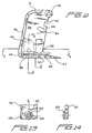
- FIGURE 1. is a side elevation, of a manually-operable cutting tool showing the cooperative parts thereof in preparation for a cutting operation to be performed upon plastic strapping;
- FIGURE 2 is a side elevation of the housing component of the cutting tool shown in FIGURE 1;
- FIGURE 3 is an end elevation of the housing component of the cutting tool as shown in FIGURE 2;
- FIGURE 4 is a cross-section through the housing component shown in FIGURE 2 as taken along the line 4-4 of FIGURE 2;
- FIGURE 5 is a cross-section through the housing component shown in FIGURE 2 as taken along the line 5-5 of FIGURE 2;
- FIGURE 6 is a cross-section through the housing shown in FIGURE 2 as taken along the line 6-6 of FIGURE 2;
- FIGURE 7 is a side elevation of the handle of the cutting tool shown in FIGURE 1;
- FIGURE 8 is an end elevation of the handle of the cutting tool shown in FIGURE 7;
- FIGURE 9 is a cross-section through the handle of the cutting tool shown in FIGURE 7 as taken along the line 9-9 of FIGURE 7;
- FIGURE 10 is a cross-section of the handle of the cutting tool shown in FIGURE 7 as taken along the line 10-10 of FIGURE 7;
- FIGURE 11 is a side elevation of the pusher component of the cutting tool shown in FIGURE 1;
- FIGURE 12 is a plan of the pusher component of the cutting tool shown in FIGURE 1;
- FIGURE 13 is a side elevation of the cutting blade component of the cutting tool shown in FIGURE 1; and
- FIGURE 14 is an end elevation of the cutting blade component shown in FIGURE 13.
-
- Referring now to the drawings, and more particularly to FIGURE 1 a manually-operable cutting tool constructed is generally indicated by the
reference character 10. Thecutting tool 10 will firstly be generally described in order to provide an overall appreciation of the construction and operation thereof, and subsequently, details of the various component parts of thetool 10 will then be described such that an appreciation can be obtained with respect to the operational interrelationship defined between the component parts of the tool. More particularly,cutting tool 10 is seen to comprise ahousing 12 upon an upper forward end of which ahandle 14 is pivotally mounted as at 16, and afirst spring 18 is interposed between thehousing 12 and thehandle 14 such that thehandle 14 is normally biased to an inoperative position as shown in FIGURE 1 wherein thetool 10 is disposed in a non-cutting mode. Acutting blade 20 is mounted upon a lower rear portion of thehousing 12, and thehandle 14 is seen to have apusher element 22 pivotally mounted upon a lower end portion thereof as at 24. Plastic strapping to be cut or severed by means of thetool 10 of the present invention is disclosed at 26, and it is seen that the lower end portion of thetool housing 12 is provided with aslot 28 into which the plastic strapping 26 is to be moved, as denoted by the arrow I, so as to encounter thecutting blade 20 whereby the plastic strapping 26 can be severed. A second set ofsprings 30, only one of which is shown, are mounted upon the lower end portion of thehandle 14 and is engaged with thepusher element 22 so as to normally bias thepusher element 22 to a position at which thepusher element 22 effectively blocks or covers the open end of theslot 28. - As can be appreciated, however, when the plastic strapping 26 is to be inserted into the
slot 28, the plastic strapping 26 is moved in the denoted direction I whereupon the plastic strapping 26 encountering thepusher element 22, thepusher element 22 is effectively moved upwardly against the biasing force of thesecond springs 30 whereby the plastic strapping 26 can be inserted into theslot 28. Upon the strapping 26 clearing or passing by the rear end portion of thepusher element 22, thesecond springs 30 will bias thepusher element 22 back to its normally biased position at which the rear end portion of thepusher element 22 now engages the rear or right edge portion of the strapping 26 as viewed in FIGURE 1, the pivotal movements of the pusher element being noted by the double arrowhead U-D. Accordingly, when thehandle 14 is pivotally moved inwardly or toward the left as viewed in FIGURE 1, the pivotal movements of thehandle 14 being denoted by means of the double arrowhead I-0, thepusher element 22 will force the strapping 26 toward the left into engagement with thecutting edge 32 of thecutting blade 20 whereby strapping 26 is cut thereby completing a strapping cutting operation. - With reference now being made to FIGURES 2-6, the details of the
housing 12 will now be described. As can best be appreciated from FIGURES 2-4, thehousing 12 is seen to comprise a horizontally disposed base orfoundation 34 and a rearwardly disposed, upstanding support member orrib 36 which is integrally connected at its lower end portion to the base orfoundation 34. A laterally central or axially disposedweb member 38 is in turn integrally connected to the upstanding support member orrib 36, and it is seen that the lower end portion of theweb member 38 is spaced from the base orfoundation 34 so as to define theaforenoted slot 28 into which the strapping 26 to be cut can be inserted. A pivot pin support orboss 40 is integrally formed at the upper forward end of theweb 38 so as to pivotally support thehandle 14 thereon, and a recessed socket orpocket portion 42 is defined within an upper forward edge portion of theweb 38 for accommodating one end of thefirst spring 18 which is adapted to be interposed between theweb portion 38 of thehousing 12 and thehandle 14 so as to normally bias thehandle 14 toward its opened position which is relatively remote from the upstanding support member orrib 36 of thehousing 12. The forwardmost end portion of the base orfoundation 34 is provided with a relatively sharp wedge-shaped portion 44 so as to enable thetool 10 to be inserted underneath the strapping 26 to be cut as well as to guide the strapping 26 into theslot 28. Lastly, as best seen or appreciated from FIGURES 4 and 6, a right side portion of theweb member 38, as well as a corresponding portion of the base orfoundation 34, is provided with arecessed region 46 which has a substantially rectangular configuration so as to house or accommodate thecutting blade 20. In addition, a substantially oval-shaped aperture 48 is defined within theweb member 38 and at a substantially central portion of therecessed region 46 so as to provide for vertical adjustment of thecutting blade 20 as will be described more fully in detail hereinafter. - With reference now being made to FIGURES 7-10, the structure of the
handle 14 will now be described in detail. As may best be appreciated from FIGURE 8, thehandle 14 is seen to essentially comprise a bifurcated structure which comprises a pair of laterally separatedside wall members end wall member 54. A recessed pocket orsocket 56 is defined within theend wall member 54 and is adapted to receive the opposite end of thefirst spring 18, and it is to be appreciated that thefirst spring 18 will be confined between theside wall members side wall members aperture apertures boss 40 so as to permit a pivot pin, not shown, to be axially disposed there-through by means of which thehandle 14 is pivotally mounted upon thehousing 12 as at 16. The lateral separation of theside wall portions handle 14 defines a central oraxial space 62 therebetween within which theforward edge portion 64 of thehousing web 38 is able to be freely accommodated when thehandle 14 is pivotally moved with respect to thehousing 12 in the opposite directions noted by the double arrowhead 1-0. In order to comfortably or ergonomically assist the pivotal movement of thehandle 14 with respect to thehousing 12, the forward vertical portion of thehandle 14 is provided withfingergrip portions 66. This structure also corresponds to the provision of the upstanding support member orrib 36 of thehousing 12 which will likewise ergonomically fit or be disposed within an operator's palm whereby thetool 10 can be easily or readily manipulated by means of one hand. It is still further noted that theweb portion 38 of thehousing 12 is provided with a substantially arcuate, oval-shaped aperture 68, and each one of theside wall portions pin 72 can be disposed such that the pivotal movement of thehandle 14 with respect to thehousing 12 is limited or confined within a predetermined range of movement. - With reference continuing to be made to FIGURES 7-9, the lower end portion of the
handle 14 further comprises a skirt portion which is defined by means of two downwardly dependentside wall portions side wall portions space 78 within which thepusher element 22 can be accommodated as can also be appreciated from FIGURE 1. As seen in FIGURE 7, each one of the dependentside wall portions pusher element 22 is pivotally mounted upon thehandle 14 as at 24. The lower end portion of thehandle 14 is further provided with a pair of laterally spacedblind bores second springs pusher element 22 are to be disposed. As was the case with thefirst spring 18, the pair ofsecond springs side wall portions springs pusher element 22. - With reference now being made to FIGURES 11 and 12, the details of the
pusher element 22 will be described. Initially, as can best be appreciated from FIGURES 1-3,5 and 6, the housing base orfoundation 34 further includes an upstanding, horizontally extendingrib 84 which is separated from the lower edge portion of theweb member 38 and axially aligned or coplanar with theweb member 38 so as to define theslot 28 therebetween. Therib 84 projects upwardly from theupper surface 86 of the base orfoundation 34 upon which thepusher element 22 is adapted to ride when thehandle 14 is moved inwardly with respect to thehousing 12 in accordance with the arrow portion I of the double arrowhead I-0. Accordingly, thepusher element 22 is provided with unique structure which permits thepusher element 22 to achieve the aforenoted movement during a strapping cutting operation. - More particularly, as was the case with the
handle 14, thepusher element 22 also comprises a bifurcated structure. As best appreciated from FIGURE 12, thepusher element 22 comprises a pair of longitudinally extending, laterally separatedside portions end portion 90. The lateral separation of theside portions axial space 92 therebetween within which theupstanding rib 84 of the housing base or foundation is able to be accommodated. Theend portion 90 is also provided with a laterally or transversely orientedthroughbore 94 for accommodating a pivot pin, not shown, whereby the pusher element is pivotally mounted upon thehandle 14 as at 24. - As can best be further appreciated from FIGURE 11, each one of the
side portions pusher element 22 comprises a rearwardly disposed end portion which comprises anundersurface portion 96 and anend surface portion 98, eachsurface portion undersurface portion 96 may be disposed at an angle of 250, whileend surface portion 98 may be disposed at an angle of 650. Accordingly, as can best be appreciated from the assembled view of FIGURE 1, when thepusher element 22 is operationally mounted upon thehandle 14, it will be seen that eachundersurface portion upper surface 86 of the base orfoundation 34 while eachend portion upper surface 86 of the base orfoundation 34 whereby theend portions cutting edge 32 of thecutting blade 20. The disposition of eachundersurface portion upper surface 86 of the base orfoundation 34, as well as the straddling in effect of eachside portion upstanding rib portion 84 of the base orfoundation 34, provides controlled stability to thepusher element 22 as the same rides or moves along theupper surface portion 86 of the base orfoundation 34 such that proper cutting forces can be generated during a cutting operation being performed upon the strapping 26. - With reference lastly being made to FIGURES 13 and 14, the details of the
cutting blade 20 will now be described. As can be seen, thecutting blade 20 is provided with a forwardly disposedbeveled portion 100 which defines the forwardly disposedcutting edge portion 32. In addition, thecutting blade 20 has upon a side portion thereof an integrally formednut portion 102 having athroughbore 104 within which a suitable fastener, not shown, can be inserted. The fastener is also adapted to be inserted through the oval-shapedaperture 48 defined within theweb member 38. It is also seen that the vertical height or extent of thecutting blade 20 is less than that of the recessedregion 46 defined within the sidewall portion of theweb member 38 and the base portion orfoundation 34. In this manner, the vertical disposition of thecutting blade 20, and more particularly, that of thecutting edge 32 of thecutting blade 20, is thus able to be positionally adjusted, when the fastener, not shown, is appropriately loosened and subsequently tightened, such that new regions of thecutting blade edge 32 can be positioned or aligned with respect to theslot 28, as thecutting blade 20 experiences wear, within which the strapping 26 to be cut is disposed so as to be cut by means of thecutting blade 20. - Thus, it may be seen that in accordance with the principles and teachings of the present invention, there has been provided a manually-operable cutting tool, for cutting or severing plastic strapping, wherein the tool is compact in size and easily manipulable by means of an operator's single hand, and wherein further, the strapping is readily able to be inserted into the housing slot and forced into contact with the cutting blade by means of the pusher element when the handle is pivotally moved relative to the housing. The interior disposition of the cutting blade also renders the tool safe for operator personnel in that the cutting edge of the blade is not externally exposed.
Claims (7)
- A manually-operated cutting tool (10) for cutting a strip of material such as plastic strapping, comprising:wherein said handle (14) comprises fingergrip portions (66) and said housing (12) comprises a palm-support portion,a housing (12) having a base portion (34), an upstanding web portion (38) integrally attached to said base portion (34), and an insertion slot (28) defined within said housing (12) between said base portion (34) and a lower end portion of said upstanding web portion (38) for permitting insertion of the strip of material into said housing;a cutting blade (20) mounted upon said housing (12); and,a handle (14) mounted upon said housing (12) for movement between a first inoperative position at which said handle (14) permits the strip of material to be disposed adjacent said cutting blade (20), and a second operative position at which said handle (14) forces the strip of material into contact with said cutting blade (20) whereby said cutting blade (20) cuts the strip of material,
characterised by a pusher element (22) pivotally mounted upon said handle (14) movable between a first position at which said pusher element (22) permits the strip of material to be inserted into said slot (28) of said housing (12) in preparation for a cutting operation by said cutting blade (20), and a second position at which said pusher element (22) engages the strip of material so as to force the strip of material into engagement with said cutting blade (20) as said handle (14) is moved from said first inoperative position to said second operative position, whereby said manually-operable cutting tool (10) is able to be manipulated by an operator in accordance with a one-handed operation. - A manually-operable cutting tool according to claim 1, wherein:said base portion (34) of said housing (12) comprises an upstanding rib member (36); andsaid pusher element (22) comprises a bifurcated structure having a pair of laterally separated side portions defining a space therebetween for accommodating said rib member (36) of said base portion (34) of said housing and for permitting movement of said pusher element (22) along said base portion (34) of said housing as said handle (14) is moved from said first inoperative position to said second operative position.
- A manually-operable cutting tool according to claim 1 or claim 2, wherein:said handle (14) comprises a bifurcated structure having a pair of laterally separated side wall portions defining a space therebetween for accommodating said web portion (38) of said housing (12) and for permitting movement of said handle (14) from said first inoperative position to said second operative position.
- A manually-operable cutting tool according to any one of the preceding claims, further comprising:means mounting said cutting blade (20) upon said housing (12) for permitting said cutting blade (20) to be adjustably movable upon said housing (12) to enable new portions of said cutting blade (20) to be positioned for performing a cutting operation as said cutting blade (20) experiences wear.
- A manually-operable cutting tool according to any one of the preceding claims, further comprising:a first spring member (18) interposed between said housing (12) and said handle (14) for normally biasing said handle (14) to said first inoperative position.
- A manually-operable cutting tool according to claim 5, wherein:a slot (68) is defined within said housing (12); anda pin (72) is mounted upon said handle (14) and disposed within said slot (68) of said housing (12) for limiting the movement of said handle (14) with respect to said housing (12) from said second operative position toward said first inoperative position under the influence of said first spring member (18).
- A manually-operable cutting tool according to any one of the preceding claims further comprising:a second spring member (30) interposed between said handle (14) and said pusher element (22) for normally biasing said pusher element (22) to said second position.
Applications Claiming Priority (2)
| Application Number | Priority Date | Filing Date | Title |
|---|---|---|---|
| US613316 | 1990-11-08 | ||
| US09/613,316 US6571477B1 (en) | 2000-07-11 | 2000-07-11 | Pocket cutter for plastic strap |
Publications (3)
| Publication Number | Publication Date |
|---|---|
| EP1179398A2 EP1179398A2 (en) | 2002-02-13 |
| EP1179398A3 EP1179398A3 (en) | 2002-10-23 |
| EP1179398B1 true EP1179398B1 (en) | 2005-08-24 |
Family
ID=24456800
Family Applications (1)
| Application Number | Title | Priority Date | Filing Date |
|---|---|---|---|
| EP01305518A Expired - Lifetime EP1179398B1 (en) | 2000-07-11 | 2001-06-26 | Cutter for plastic strap |
Country Status (8)
| Country | Link |
|---|---|
| US (1) | US6571477B1 (en) |
| EP (1) | EP1179398B1 (en) |
| JP (1) | JP2002087416A (en) |
| KR (1) | KR100759321B1 (en) |
| CN (1) | CN1244437C (en) |
| AT (1) | ATE302671T1 (en) |
| DE (1) | DE60112855T2 (en) |
| TW (1) | TW548165B (en) |
Families Citing this family (9)
| Publication number | Priority date | Publication date | Assignee | Title |
|---|---|---|---|---|
| US6807737B1 (en) * | 2002-05-21 | 2004-10-26 | Christina K. Davia | Ergonomic opener for intravenous bag packaging |
| US6880250B1 (en) * | 2003-06-18 | 2005-04-19 | Elias Tamez | Letter opener |
| US20070044322A1 (en) * | 2004-01-02 | 2007-03-01 | Trbovich Nicholas D Jr | Multi-tool with strap cutter |
| AT500136B1 (en) * | 2004-05-12 | 2007-03-15 | Edgar Lill | CUTTER |
| CA2524426C (en) * | 2004-10-27 | 2013-01-15 | Andreas Stihl Ag & Co. Kg | Protective shield for a trimmer |
| US8701295B2 (en) * | 2009-11-20 | 2014-04-22 | Joseph Clearman | Variable pressure cutting devices |
| US20110162215A1 (en) * | 2010-01-01 | 2011-07-07 | Hsiu-Man Yu Chen | Letter opener |
| CH708269B1 (en) * | 2013-06-25 | 2017-01-13 | Zeltner Markus | Letter opener with protected blade and seesaw. |
| US10875201B2 (en) | 2018-04-04 | 2020-12-29 | Swanstrom Tools Usa Inc. | Relief guard for hand tools |
Family Cites Families (13)
| Publication number | Priority date | Publication date | Assignee | Title |
|---|---|---|---|---|
| US533164A (en) * | 1895-01-29 | Potato-cutter | ||
| US501928A (en) * | 1893-07-25 | Island | ||
| US1356941A (en) * | 1920-04-01 | 1920-10-26 | Albert P Cunningham | Poultry-killer |
| US1478684A (en) * | 1923-01-25 | 1923-12-25 | Henry O Taylor | Vegetable cutter |
| US2120375A (en) * | 1936-06-10 | 1938-06-14 | George W Shaver | Slicing machine |
| US2283029A (en) * | 1938-10-12 | 1942-05-12 | Bakewell Sidney | Potato-cutting device |
| US2407924A (en) * | 1943-05-25 | 1946-09-17 | Louis X Garfunkel | Food slicing machine having stationary knives and a follower feed |
| US2497289A (en) * | 1947-10-02 | 1950-02-14 | Bloomfield Harold | Potato cutter |
| US3114277A (en) * | 1961-04-05 | 1963-12-17 | Bert J Clendenin | Wire stripping tool |
| US4028802A (en) * | 1975-11-06 | 1977-06-14 | Rug Crafters | Loop cutting tool |
| US4644646A (en) | 1982-06-10 | 1987-02-24 | Ladin Eli M | Strap cutting tool |
| IL78704A0 (en) | 1985-05-14 | 1986-08-31 | Ruyter J A De | Cutting appliance designed particularly for medical dressings |
| FR2581915B1 (en) | 1985-05-14 | 1987-10-30 | Ruyter Jackie De | CUTTER DEVICE FOR STRIPS |
-
2000
- 2000-07-11 US US09/613,316 patent/US6571477B1/en not_active Expired - Fee Related
-
2001
- 2001-06-15 TW TW090114649A patent/TW548165B/en not_active IP Right Cessation
- 2001-06-26 AT AT01305518T patent/ATE302671T1/en not_active IP Right Cessation
- 2001-06-26 EP EP01305518A patent/EP1179398B1/en not_active Expired - Lifetime
- 2001-06-26 DE DE60112855T patent/DE60112855T2/en not_active Expired - Lifetime
- 2001-07-06 CN CNB011202181A patent/CN1244437C/en not_active Expired - Fee Related
- 2001-07-07 KR KR1020010040613A patent/KR100759321B1/en not_active Expired - Fee Related
- 2001-07-10 JP JP2001209279A patent/JP2002087416A/en active Pending
Also Published As
| Publication number | Publication date |
|---|---|
| DE60112855T2 (en) | 2006-03-09 |
| KR100759321B1 (en) | 2007-09-18 |
| JP2002087416A (en) | 2002-03-27 |
| US6571477B1 (en) | 2003-06-03 |
| CN1244437C (en) | 2006-03-08 |
| DE60112855D1 (en) | 2005-09-29 |
| TW548165B (en) | 2003-08-21 |
| KR20020006434A (en) | 2002-01-19 |
| EP1179398A2 (en) | 2002-02-13 |
| ATE302671T1 (en) | 2005-09-15 |
| CN1332071A (en) | 2002-01-23 |
| EP1179398A3 (en) | 2002-10-23 |
Similar Documents
| Publication | Publication Date | Title |
|---|---|---|
| KR0149244B1 (en) | Compound Resin Pruning Tool | |
| US5398576A (en) | Cutting device for a roll of protective film | |
| US6223639B1 (en) | Aluminum foil safety fixture | |
| EP1306645A1 (en) | Holder assembly for hand-held device | |
| US5943778A (en) | Easy cutter | |
| US20020096031A1 (en) | Manual paper cutter | |
| EP1110653B1 (en) | Window lockout mechanism for power tool | |
| EP1179398A2 (en) | Cutter for plastic strap | |
| GB1564199A (en) | Tools for stripping sheating from cables and the like | |
| US5388619A (en) | Clamp tightening device | |
| US5117557A (en) | Cutting device | |
| CN102131380A (en) | Vegetation cutting tool | |
| JP2574696B2 (en) | Cutter | |
| US4443942A (en) | Tool for trimming lapping edge portions of sheet material | |
| US6745473B2 (en) | Cable sheathing slitter for a wire stripper tool | |
| CA1271392A (en) | Locking cover assembly for use with a chain saw | |
| US4510688A (en) | Seam ripper | |
| US20010007214A1 (en) | Force-saving pliers | |
| US20020035789A1 (en) | Cutting device | |
| US6123001A (en) | Detonating cord cutter | |
| GB1596307A (en) | Safety belt fitted with webbing cutter | |
| US20070050985A1 (en) | Cutting tool for strap | |
| JP3114506U (en) | Cutter | |
| AU569134B2 (en) | Scissor action cutting device | |
| KR950006509Y1 (en) | Scissors with staple remover |
Legal Events
| Date | Code | Title | Description |
|---|---|---|---|
| PUAI | Public reference made under article 153(3) epc to a published international application that has entered the european phase |
Free format text: ORIGINAL CODE: 0009012 |
|
| AK | Designated contracting states |
Kind code of ref document: A2 Designated state(s): AT BE CH CY DE DK ES FI FR GB GR IE IT LI LU MC NL PT SE TR |
|
| AX | Request for extension of the european patent |
Free format text: AL;LT;LV;MK;RO;SI |
|
| PUAL | Search report despatched |
Free format text: ORIGINAL CODE: 0009013 |
|
| AK | Designated contracting states |
Kind code of ref document: A3 Designated state(s): AT BE CH CY DE DK ES FI FR GB GR IE IT LI LU MC NL PT SE TR |
|
| AX | Request for extension of the european patent |
Free format text: AL;LT;LV;MK;RO;SI |
|
| RIC1 | Information provided on ipc code assigned before grant |
Free format text: 7B 26B 27/00 A, 7B 65B 69/00 B |
|
| 17P | Request for examination filed |
Effective date: 20030409 |
|
| AKX | Designation fees paid |
Designated state(s): AT BE CH CY DE DK ES FI FR GB GR IE IT LI LU MC NL PT SE TR |
|
| 17Q | First examination report despatched |
Effective date: 20030821 |
|
| GRAP | Despatch of communication of intention to grant a patent |
Free format text: ORIGINAL CODE: EPIDOSNIGR1 |
|
| GRAS | Grant fee paid |
Free format text: ORIGINAL CODE: EPIDOSNIGR3 |
|
| GRAA | (expected) grant |
Free format text: ORIGINAL CODE: 0009210 |
|
| AK | Designated contracting states |
Kind code of ref document: B1 Designated state(s): AT BE CH CY DE DK ES FI FR GB GR IE IT LI LU MC NL PT SE TR |
|
| PG25 | Lapsed in a contracting state [announced via postgrant information from national office to epo] |
Ref country code: IT Free format text: LAPSE BECAUSE OF FAILURE TO SUBMIT A TRANSLATION OF THE DESCRIPTION OR TO PAY THE FEE WITHIN THE PRESCRIBED TIME-LIMIT;WARNING: LAPSES OF ITALIAN PATENTS WITH EFFECTIVE DATE BEFORE 2007 MAY HAVE OCCURRED AT ANY TIME BEFORE 2007. THE CORRECT EFFECTIVE DATE MAY BE DIFFERENT FROM THE ONE RECORDED. Effective date: 20050824 Ref country code: FI Free format text: LAPSE BECAUSE OF FAILURE TO SUBMIT A TRANSLATION OF THE DESCRIPTION OR TO PAY THE FEE WITHIN THE PRESCRIBED TIME-LIMIT Effective date: 20050824 Ref country code: BE Free format text: LAPSE BECAUSE OF FAILURE TO SUBMIT A TRANSLATION OF THE DESCRIPTION OR TO PAY THE FEE WITHIN THE PRESCRIBED TIME-LIMIT Effective date: 20050824 Ref country code: CH Free format text: LAPSE BECAUSE OF FAILURE TO SUBMIT A TRANSLATION OF THE DESCRIPTION OR TO PAY THE FEE WITHIN THE PRESCRIBED TIME-LIMIT Effective date: 20050824 Ref country code: AT Free format text: LAPSE BECAUSE OF FAILURE TO SUBMIT A TRANSLATION OF THE DESCRIPTION OR TO PAY THE FEE WITHIN THE PRESCRIBED TIME-LIMIT Effective date: 20050824 Ref country code: LI Free format text: LAPSE BECAUSE OF FAILURE TO SUBMIT A TRANSLATION OF THE DESCRIPTION OR TO PAY THE FEE WITHIN THE PRESCRIBED TIME-LIMIT Effective date: 20050824 Ref country code: NL Free format text: LAPSE BECAUSE OF FAILURE TO SUBMIT A TRANSLATION OF THE DESCRIPTION OR TO PAY THE FEE WITHIN THE PRESCRIBED TIME-LIMIT Effective date: 20050824 |
|
| REG | Reference to a national code |
Ref country code: GB Ref legal event code: FG4D |
|
| REG | Reference to a national code |
Ref country code: CH Ref legal event code: EP |
|
| REG | Reference to a national code |
Ref country code: IE Ref legal event code: FG4D |
|
| REF | Corresponds to: |
Ref document number: 60112855 Country of ref document: DE Date of ref document: 20050929 Kind code of ref document: P |
|
| PG25 | Lapsed in a contracting state [announced via postgrant information from national office to epo] |
Ref country code: GR Free format text: LAPSE BECAUSE OF FAILURE TO SUBMIT A TRANSLATION OF THE DESCRIPTION OR TO PAY THE FEE WITHIN THE PRESCRIBED TIME-LIMIT Effective date: 20051124 Ref country code: DK Free format text: LAPSE BECAUSE OF FAILURE TO SUBMIT A TRANSLATION OF THE DESCRIPTION OR TO PAY THE FEE WITHIN THE PRESCRIBED TIME-LIMIT Effective date: 20051124 Ref country code: SE Free format text: LAPSE BECAUSE OF FAILURE TO SUBMIT A TRANSLATION OF THE DESCRIPTION OR TO PAY THE FEE WITHIN THE PRESCRIBED TIME-LIMIT Effective date: 20051124 |
|
| PG25 | Lapsed in a contracting state [announced via postgrant information from national office to epo] |
Ref country code: ES Free format text: LAPSE BECAUSE OF FAILURE TO SUBMIT A TRANSLATION OF THE DESCRIPTION OR TO PAY THE FEE WITHIN THE PRESCRIBED TIME-LIMIT Effective date: 20051205 |
|
| PG25 | Lapsed in a contracting state [announced via postgrant information from national office to epo] |
Ref country code: PT Free format text: LAPSE BECAUSE OF FAILURE TO SUBMIT A TRANSLATION OF THE DESCRIPTION OR TO PAY THE FEE WITHIN THE PRESCRIBED TIME-LIMIT Effective date: 20060124 |
|
| NLV1 | Nl: lapsed or annulled due to failure to fulfill the requirements of art. 29p and 29m of the patents act | ||
| REG | Reference to a national code |
Ref country code: CH Ref legal event code: PL |
|
| PG25 | Lapsed in a contracting state [announced via postgrant information from national office to epo] |
Ref country code: IE Free format text: LAPSE BECAUSE OF NON-PAYMENT OF DUE FEES Effective date: 20060626 Ref country code: GB Free format text: LAPSE BECAUSE OF NON-PAYMENT OF DUE FEES Effective date: 20060626 |
|
| PG25 | Lapsed in a contracting state [announced via postgrant information from national office to epo] |
Ref country code: MC Free format text: LAPSE BECAUSE OF NON-PAYMENT OF DUE FEES Effective date: 20060630 |
|
| PLBE | No opposition filed within time limit |
Free format text: ORIGINAL CODE: 0009261 |
|
| STAA | Information on the status of an ep patent application or granted ep patent |
Free format text: STATUS: NO OPPOSITION FILED WITHIN TIME LIMIT |
|
| 26N | No opposition filed |
Effective date: 20060526 |
|
| EN | Fr: translation not filed | ||
| PG25 | Lapsed in a contracting state [announced via postgrant information from national office to epo] |
Ref country code: FR Free format text: LAPSE BECAUSE OF FAILURE TO SUBMIT A TRANSLATION OF THE DESCRIPTION OR TO PAY THE FEE WITHIN THE PRESCRIBED TIME-LIMIT Effective date: 20061020 |
|
| GBPC | Gb: european patent ceased through non-payment of renewal fee |
Effective date: 20060626 |
|
| REG | Reference to a national code |
Ref country code: IE Ref legal event code: MM4A |
|
| PG25 | Lapsed in a contracting state [announced via postgrant information from national office to epo] |
Ref country code: TR Free format text: LAPSE BECAUSE OF FAILURE TO SUBMIT A TRANSLATION OF THE DESCRIPTION OR TO PAY THE FEE WITHIN THE PRESCRIBED TIME-LIMIT Effective date: 20050824 Ref country code: LU Free format text: LAPSE BECAUSE OF NON-PAYMENT OF DUE FEES Effective date: 20060626 |
|
| PG25 | Lapsed in a contracting state [announced via postgrant information from national office to epo] |
Ref country code: CY Free format text: LAPSE BECAUSE OF FAILURE TO SUBMIT A TRANSLATION OF THE DESCRIPTION OR TO PAY THE FEE WITHIN THE PRESCRIBED TIME-LIMIT Effective date: 20050824 Ref country code: FR Free format text: LAPSE BECAUSE OF FAILURE TO SUBMIT A TRANSLATION OF THE DESCRIPTION OR TO PAY THE FEE WITHIN THE PRESCRIBED TIME-LIMIT Effective date: 20050824 |
|
| PGFP | Annual fee paid to national office [announced via postgrant information from national office to epo] |
Ref country code: DE Payment date: 20110629 Year of fee payment: 11 |
|
| REG | Reference to a national code |
Ref country code: DE Ref legal event code: R119 Ref document number: 60112855 Country of ref document: DE Effective date: 20130101 |
|
| PG25 | Lapsed in a contracting state [announced via postgrant information from national office to epo] |
Ref country code: DE Free format text: LAPSE BECAUSE OF NON-PAYMENT OF DUE FEES Effective date: 20130101 |