EP1178859B1 - Vortex static mixer and method employing same - Google Patents
Vortex static mixer and method employing same Download PDFInfo
- Publication number
- EP1178859B1 EP1178859B1 EP00930114A EP00930114A EP1178859B1 EP 1178859 B1 EP1178859 B1 EP 1178859B1 EP 00930114 A EP00930114 A EP 00930114A EP 00930114 A EP00930114 A EP 00930114A EP 1178859 B1 EP1178859 B1 EP 1178859B1
- Authority
- EP
- European Patent Office
- Prior art keywords
- set forth
- conduit
- baffle
- mixer
- static fluid
- Prior art date
- Legal status (The legal status is an assumption and is not a legal conclusion. Google has not performed a legal analysis and makes no representation as to the accuracy of the status listed.)
- Expired - Lifetime
Links
- 230000003068 static effect Effects 0.000 title claims abstract description 65
- 238000000034 method Methods 0.000 title claims description 9
- 239000012530 fluid Substances 0.000 claims abstract description 121
- 239000002245 particle Substances 0.000 claims abstract description 9
- 239000007787 solid Substances 0.000 claims abstract description 9
- 238000011144 upstream manufacturing Methods 0.000 claims description 37
- 239000000654 additive Substances 0.000 claims description 12
- 230000000996 additive effect Effects 0.000 claims description 9
- 230000002093 peripheral effect Effects 0.000 claims description 3
- 238000009826 distribution Methods 0.000 description 5
- 239000000463 material Substances 0.000 description 5
- 238000010276 construction Methods 0.000 description 4
- 238000004519 manufacturing process Methods 0.000 description 4
- 239000000126 substance Substances 0.000 description 4
- 239000007788 liquid Substances 0.000 description 3
- 238000003466 welding Methods 0.000 description 3
- 239000000835 fiber Substances 0.000 description 2
- XLYOFNOQVPJJNP-UHFFFAOYSA-N water Substances O XLYOFNOQVPJJNP-UHFFFAOYSA-N 0.000 description 2
- 230000004323 axial length Effects 0.000 description 1
- 238000004140 cleaning Methods 0.000 description 1
- 238000010790 dilution Methods 0.000 description 1
- 239000012895 dilution Substances 0.000 description 1
- 230000000694 effects Effects 0.000 description 1
- 229930195733 hydrocarbon Natural products 0.000 description 1
- 150000002430 hydrocarbons Chemical class 0.000 description 1
- 230000002452 interceptive effect Effects 0.000 description 1
- 238000012423 maintenance Methods 0.000 description 1
- 239000000203 mixture Substances 0.000 description 1
- 230000000737 periodic effect Effects 0.000 description 1
- 239000012266 salt solution Substances 0.000 description 1
- 230000035945 sensitivity Effects 0.000 description 1
- 238000000926 separation method Methods 0.000 description 1
- 238000009827 uniform distribution Methods 0.000 description 1
Images

Classifications
-
- B—PERFORMING OPERATIONS; TRANSPORTING
- B01—PHYSICAL OR CHEMICAL PROCESSES OR APPARATUS IN GENERAL
- B01F—MIXING, e.g. DISSOLVING, EMULSIFYING OR DISPERSING
- B01F25/00—Flow mixers; Mixers for falling materials, e.g. solid particles
- B01F25/30—Injector mixers
- B01F25/31—Injector mixers in conduits or tubes through which the main component flows
- B01F25/313—Injector mixers in conduits or tubes through which the main component flows wherein additional components are introduced in the centre of the conduit
- B01F25/3131—Injector mixers in conduits or tubes through which the main component flows wherein additional components are introduced in the centre of the conduit with additional mixing means other than injector mixers, e.g. screens, baffles or rotating elements
-
- B—PERFORMING OPERATIONS; TRANSPORTING
- B01—PHYSICAL OR CHEMICAL PROCESSES OR APPARATUS IN GENERAL
- B01F—MIXING, e.g. DISSOLVING, EMULSIFYING OR DISPERSING
- B01F25/00—Flow mixers; Mixers for falling materials, e.g. solid particles
- B01F25/40—Static mixers
- B01F25/42—Static mixers in which the mixing is affected by moving the components jointly in changing directions, e.g. in tubes provided with baffles or obstructions
- B01F25/43—Mixing tubes, e.g. wherein the material is moved in a radial or partly reversed direction
- B01F25/431—Straight mixing tubes with baffles or obstructions that do not cause substantial pressure drop; Baffles therefor
- B01F25/4315—Straight mixing tubes with baffles or obstructions that do not cause substantial pressure drop; Baffles therefor the baffles being deformed flat pieces of material
-
- B—PERFORMING OPERATIONS; TRANSPORTING
- B01—PHYSICAL OR CHEMICAL PROCESSES OR APPARATUS IN GENERAL
- B01F—MIXING, e.g. DISSOLVING, EMULSIFYING OR DISPERSING
- B01F25/00—Flow mixers; Mixers for falling materials, e.g. solid particles
- B01F25/40—Static mixers
- B01F25/42—Static mixers in which the mixing is affected by moving the components jointly in changing directions, e.g. in tubes provided with baffles or obstructions
- B01F25/43—Mixing tubes, e.g. wherein the material is moved in a radial or partly reversed direction
- B01F25/431—Straight mixing tubes with baffles or obstructions that do not cause substantial pressure drop; Baffles therefor
- B01F25/4316—Straight mixing tubes with baffles or obstructions that do not cause substantial pressure drop; Baffles therefor the baffles being flat pieces of material, e.g. intermeshing, fixed to the wall or fixed on a central rod
-
- B—PERFORMING OPERATIONS; TRANSPORTING
- B01—PHYSICAL OR CHEMICAL PROCESSES OR APPARATUS IN GENERAL
- B01F—MIXING, e.g. DISSOLVING, EMULSIFYING OR DISPERSING
- B01F25/00—Flow mixers; Mixers for falling materials, e.g. solid particles
- B01F25/40—Static mixers
- B01F25/42—Static mixers in which the mixing is affected by moving the components jointly in changing directions, e.g. in tubes provided with baffles or obstructions
- B01F25/43—Mixing tubes, e.g. wherein the material is moved in a radial or partly reversed direction
- B01F25/431—Straight mixing tubes with baffles or obstructions that do not cause substantial pressure drop; Baffles therefor
- B01F25/4316—Straight mixing tubes with baffles or obstructions that do not cause substantial pressure drop; Baffles therefor the baffles being flat pieces of material, e.g. intermeshing, fixed to the wall or fixed on a central rod
- B01F25/43161—Straight mixing tubes with baffles or obstructions that do not cause substantial pressure drop; Baffles therefor the baffles being flat pieces of material, e.g. intermeshing, fixed to the wall or fixed on a central rod composed of consecutive sections of flat pieces of material
-
- B—PERFORMING OPERATIONS; TRANSPORTING
- B01—PHYSICAL OR CHEMICAL PROCESSES OR APPARATUS IN GENERAL
- B01F—MIXING, e.g. DISSOLVING, EMULSIFYING OR DISPERSING
- B01F25/00—Flow mixers; Mixers for falling materials, e.g. solid particles
- B01F25/40—Static mixers
- B01F25/42—Static mixers in which the mixing is affected by moving the components jointly in changing directions, e.g. in tubes provided with baffles or obstructions
- B01F25/43—Mixing tubes, e.g. wherein the material is moved in a radial or partly reversed direction
- B01F25/431—Straight mixing tubes with baffles or obstructions that do not cause substantial pressure drop; Baffles therefor
- B01F25/43197—Straight mixing tubes with baffles or obstructions that do not cause substantial pressure drop; Baffles therefor characterised by the mounting of the baffles or obstructions
- B01F25/431971—Mounted on the wall
-
- B—PERFORMING OPERATIONS; TRANSPORTING
- B01—PHYSICAL OR CHEMICAL PROCESSES OR APPARATUS IN GENERAL
- B01F—MIXING, e.g. DISSOLVING, EMULSIFYING OR DISPERSING
- B01F25/00—Flow mixers; Mixers for falling materials, e.g. solid particles
- B01F25/40—Static mixers
- B01F25/42—Static mixers in which the mixing is affected by moving the components jointly in changing directions, e.g. in tubes provided with baffles or obstructions
- B01F25/43—Mixing tubes, e.g. wherein the material is moved in a radial or partly reversed direction
- B01F25/431—Straight mixing tubes with baffles or obstructions that do not cause substantial pressure drop; Baffles therefor
- B01F25/4319—Tubular elements
Definitions
- the present application relates generally to static fluid mixers and particularly to static mixers which are useful in generating fluid mixing vortices.
- the application also relates to methods for mixing fluids using such static mixers.
- Static mixers positioned within pipes or other conduits are used in a variety of applications to facilitate mixing of one or more fluid streams flowing within the conduits.
- static mixers are used to cause a homogenous distribution of a gas or solid particles within a liquid stream, for mixing of two or more gas or liquid streams, and for mixing a single fluid stream to cause a more uniform distribution of temperature, velocity or other fluid properties.
- vortex mixers Certain types of static mixers, known as vortex mixers, are specifically designed to cause mixing by creating swirling vortices of fluid. Examples of such vortex mixers are shown in U.S. Patent No.4,307,697 to Ong, U.S. Patent No.5,330,267 to Tauscher, U.S. Patent No. 5,456,533 to Streiff et al., U.S. Patent Nos.4,929,088 and 4,981,368 to Smith, U.S. Patent No.5,489,153, and U.S. Patent No.5,813,762. Another example of a static mixer is shown in U.S.
- Patent No.5,758,967 to King disclosing a stationary material mixing apparatus which includes a plurality of mixing elements characterized as having no edges perpendicular to the longitude axis. These mixing elements are connected, along a portion of the peripheral edges thereof, to the inner surface of the conduit.
- a vortex mixer It is generally desirable for a vortex mixer to provide both a short mixing flow path and a small pressure loss under a variety of different flow conditions and fluid compositions. In addition to achieving high efficiency, it is also desirable for the vortex mixer to be of simple, yet durable, construction for ease of fabrication and reduced cost. The above-referenced vortex mixers meet these objectives to varying degrees; however, the need for an improved vortex mixer continues.
- a static mixer which, in the preferred embodiment, uses only two baffle members positioned within a preselected length of conduit, one baffle member being positioned downstream from and at approximately a 90 degree offset from the other baffle member.
- Each baffle member is constructed in a manner to create a pair of counter-rotating vortices that are able to spread across the entire cross section of the conduit. Because of the offset baffle members, the static mixer produces mixing distribution in two main directions across the cross section of fluid flow, further contributing to homogenous mixing along a relatively short length of conduit and with a minimum of pressure drop.
- the invention provides a static fluid mixer that comprises an elongated fluid flow conduit having a centrally located longitudinally extending axis and an inner generally cylindrical wall extending around said axis and defining a fluid flow path within the conduit which extends along said central axis. Also the mixer includes a first elongated inclined baffle member positioned in said fluid flow path at a first location in said conduit and a second elongated inclined baffle member positioned in said fluid flow path at a second location in said conduit. The second location is offset circumferentially from the first location and the same is spaced longitudinally of the conduit from said first location.
- the arrangement of the baffle members is such that the mixer includes no additional baffle members which are aligned either circumferentially or longitudinally with either the first baffle member or the second baffle member.
- the invention provides a static fluid mixer comprising an elongated fluid flow conduit having a centrally located longitudinally extending axis and an inner generally cylindrical wall extending around said axis and defining a fluid flow path within the conduit which extends along said central axis.
- the mixer includes a first elongated inclined baffle member positioned in said fluid flow path at a first location in said conduit.
- the first baffle member is in the form of a plate having an upstream end, a downstream end and a longitudinal axis.
- the upstream end of the first baffle member is spaced radially from the wall a first distance which is less than a radius of the conduit, and the downstream end of the first baffle member is spaced radially from the conduit a second distance which is greater than said first distance.
- the mixer further includes a second elongated inclined baffle member positioned in said fluid flow path at a second location in said conduit.
- the second baffle member also is preferably in the form of a plate having an upstream end, a downstream end and a longitudinal axis.
- the upstream end of the second baffle member is spaced radially from the wall a third distance which is less than the radius of the conduit, and the downstream end of the first baffle member is spaced radially from the wall a fourth distance which is greater than said third distance.
- the second and fourth distances are such that the baffle members span approximately 70 percent of the diameter of the conduit.
- the first and third distances comprise approximately 4 percent of the diameter of the conduit.
- the second location in the conduit is preferably offset circumferentially from the first location and spaced longitudinally of the conduit a fifth distance from said first location.
- the mixer may also include a mounting element for each of said baffle members.
- these mounting elements may extend radially of the conduit between a downstream face of a respective baffle and said wall.
- the mounting elements may each be in the form of a member having an edge which contacts the wall of the conduit along a line which is essentially parallel with the central axis.
- at least one of the mounting elements may be in the form of a sparger pipe.
- the baffle members are of essentially the same shape, the first and third distances are essentially the same, and the second and fourth distances are essentially the same.
- the members may be plates which are trapezoidal in shape.
- the first and third distances are sufficiently large to permit portions of the fluid flowing through the conduit to pass between the upstream ends of the baffle members and the wall.
- downstream ends of the baffle plate members may have laterally spaced corners which are arranged to create counter-rotating vortices in the fluid flowing through the conduit. This arrangement facilitates thorough mixing of the materials flowing through the conduit.
- the longitudinal distance between the first and second locations where the baffle members are positioned should be in the range of from approximately 2 times to approximately 10 times greater than the radius of the conduit. Ideally, such longitudinal distance may be approximately 4 times larger than said radius.
- the baffle members may be offset circumferentially approximately 90° apart.
- a longitudinal axis of each of the baffle members may be inclined at an angle in the range of from about 20 to about 60 degrees relative to the central axis of the conduit.
- the longitudinal axes of the baffle members may be inclined at an angle in the range of from about 30 to about 50 degrees relative to the central axis of the conduit.
- the longitudinal axes of the baffle members may each be inclined at an angle of about 35 degrees relative to the central axis of the conduit.
- the upstream ends of the baffle members may be inclined at an angle of about 90 degrees relative to said axis.
- the baffle members may ideally be plates which are trapezoidal in shape with downstream ends which are smaller than the upstream ends.
- the baffle plates may have any one of a variety of shapes and configurations. That is to say, the members may be plates which are essentially planar in transverse cross-sectional configuration. Alternatively, the members may be essentially non-planar in transverse cross-sectional configuration, essentially concave in transverse cross-sectional configuration, essentially convex in transverse cross-sectional configuration, or essentially V-shaped in transverse cross-sectional configuration.
- the baffle members may also include a hollow internal or external passageway providing a flow path for introducing an additive into a flow of fluids passing through the conduit. Alternatively, the baffle members may be in the form of porous and/or foraminous plates.
- the invention further provides a method of mixing one or more fluid streams comprising providing a static fluid mixer as described above and causing one or more fluid streams to flow along the fluid flow path defined by the conduit.
- the invention also provides a method of mixing solid particles with one or more fluid streams comprising providing a static fluid mixer as described above and causing a stream of solid particles and one or more fluid streams to flow along the fluid flow path defined by the conduit.
- Mixer 10 includes an elongated fluid flow conduit 12 having a centrally located longitudinally extending axis 14 and an inner generally cylindrical wall 16 extending around axis 14. Conduit 12 defines a fluid flow path 18 therewithin.
- An elongated inclined baffle member in the form of plate 20 is positioned in flow path 18 at a location 22 on wall 16.
- Plate 20 has an upstream end 24, a downstream end 26 and a longitudinal axis 28. Upstream end 24 is preferably spaced radially a distance D1 from location 22 on wall 16.
- distance D1 is generally less than the radius of conduit 12.
- end 24 may be positioned in contact with wall 16 with adequate results if such configuration is desirable. Since plate 20 projects across flow path 18, it is clear that downstream end 26 will be spaced radially from location 22 a distance D2 which is greater than distance D1.
- Plate 30 Another elongated inclined baffle member in the form of a plate 30 is positioned in flow path 18 at a location 32 on wall 16.
- Plate 30 has an upstream end 34, a downstream end 36 and a longitudinal axis 38.
- Upstream end 34 is also preferably spaced radially from location 32 on wall 16 a distance D3 which again is less than the radius of conduit 12.
- Downstream end 36 is spaced radially from location 32 a distance D4 which is greater than distance D3.
- plates 20 and 30 may preferably be trapezoidal in shape and the lateral dimensions of downstream ends 26 and 36 may preferably be less than the respective lateral dimensions of upstream ends 24 and 34.
- locations 22 and 32 and therefore baffle plates 20 and 30 are spaced apart longitudinally of conduit 12 a distance D5
- locations 22 and 32 and therefore baffle plates 20 and 30 are also offset circumferentially about the axis 14, preferably at an angle of about 90°; however, the desired offset angle may be more or less than 90° as may be determined empirically depending upon the nature of the fluid to be mixed.
- the distance D5 between locations 22 and 32 may preferably be within the range of from about 2 to about 10 times as large as the internal radius of conduit 12. Ideally, the distance D5 should be about 4 times as large as the internal radius of conduit 12.
- baffle plates 20 and 30 may be of the same shape.
- the distances D1 and D3 may preferably be about the same, and the distances D2 and D4 may also be about the same.
- the distances D 1 and D3 should preferably be sufficient to permit portions of the fluid flowing along flow path 18 and thereby through conduit 12 to pass between upstream ends 24 and 34 and wall 16. This may prevent eddy currents and dead spots from developing behind plates 20 and 30.
- Plates 20 and 30 may preferably have a longitudinal dimension L that is sufficient to span 50 to 75 percent of the diameter of conduit 12. Ideally this dimension L should be such that the plates span about 70 percent of the diameter of conduit 12. Moreover, plates 20 and 30 may preferably be inclined at an angle within the range of from about 20 to about 60 degrees relative to axis 14. Even more preferably this angle of inclination may be within the range of from about 30 to about 50 degrees. Ideally this angle of inclination may be about 35 degrees. As can be seen from Figs. 3 and 4, the upstream ends 24 and 34 of plates 20 and 30 may preferably be relatively straight and the same may extend laterally at an angle of approximately 90 degrees relative to axis 14.
- downstream ends 26 and 36 of plates 20 and 30 provide laterally spaced corners 80 to create counter-rotating vortices 40 in the fluid passing through conduit 12 along path 18. These vortices 40 work together to insure thorough mixing of the materials to be mixed throughout the entire extent of the interior of conduit 12.
- Baffle plates 20 and 30 may be connected to wall 16 by respective mounting braces in the form of plates 60 and 62 which extend radially of conduit 12 between wall 16 and the respective downstream faces 64 and 66 of plates 20 and 30. As shown, plates 60 and 62 have respective edges 68 and 70 which contact wall 16 on a line which extends longitudinally of conduit 12 along flow path 18. Braces 60 and 62 preferably comprise flat plates that may be affixed to the conduit wall 16 and faces 64 and 66 of the baffle members 20 and 30 by welding or the like. The braces 60 and 62 are oriented so as to present as small a profile as possible in the direction of fluid flow and preferably lies in a plane parallel to the direction of fluid flow.
- braces 60 and 62 may just as well be attached to a ring structure that is inserted into the conduit 16 and is in turn affixed to the conduit wall by friction or other suitable means.
- a ring structure is it can be readily removed or replaced and can be used to quickly retrofit an existing conduit.
- the conduit 12 in which the baffle members 20 and 30 are positioned may be a pipe, duct, tube, trough or other device for carrying one or more fluid streams.
- the conduit is typically of circular cross-section, but may instead be oval, square, rectangular or other desired polygonal or other shape.
- the conduit may include a sparger pipe 85 (Figs. 7-14) or other device for introducing one or more fluids or substances such as solid particles into the main fluid flow channel in a known manner and location.
- the sparger pipe 85 may also be used as a mounting element for one or more of the baffle members as shown in Figs. 7-10.
- FIG. 5 and 6 another embodiment of the invention is shown.
- the arrangement is essentially the same as the embodiment of Figs. 1, 2 and 3, except that the upstream ends 46 and 48 of the baffle plates are arcuate and have a configuration which corresponds generally with the curvature of wall 16.
- arcuate slots 50 and 52 are presented between wall 16 and the arcuate ends 46 and 48.
- slots 50 and 52 should be of ample size to permit portions of the fluid flowing through conduit 12 to pass between ends 46 and 48 and wall 16.
- the width of slots 50 and 52 may ideally be about 4 percent of the internal diameter of conduit 12.
- baffle members Although other known vortex static mixers are known to employ two or more baffle members at each of multiple locations along the axial length of the conduit, the present invention is directed to the use of only a single baffle member at each of two locations spaced a preselected distance apart in the direction of fluid flow within the conduit, and offset a preselected degree along the conduit wall in the transverse direction.
- This arrangement of baffle members allows a distribution of inhomogeneity over the entire cross section of conduit in a first main mixing direction as the fluid stream encounters the first baffle member, followed by distribution of the inhomogeneity over the entire cross section of the conduit in a second main direction as the fluid stream encounters the second baffle member.
- the first and second main mixing directions are similarly offset so that more complete and uniform mixing can occur with resulting increases in homogeneity.
- the use of only a single baffle member at each location facilitates uniform mixing across the entire conduit cross section by allowing the two counter-rotating vortices generated by each baffle member to expand across the entire cross section of the conduit.
- the use of multiple baffle members at each location might otherwise cause maldistribution of the fluid stream as a result of the production of multiple, interfering vortices.
- Sparger pipes used for introducing or dosing additives, such as additional fluid streams or substances, are preferably positioned so that they do not interfere with the counter-rotating vortices formed by the baffle members.
- Sparger pipes may preferably be located upstream from, or at, the upstream baffle member so that the additives are introduced upstream from the baffle member, at one or more locations along the upstream face of the baffle member, or even along the downstream face of the baffle member so that a portion of the fluid flowing along the flow path flows around the outside of the baffle member whilst another portion is introduced downstream of the baffle member.
- Fig.9 illustrates a particularly preferred example of a dosing structure comprising a sparger pipe 85.
- sparger pipe 85 lies on the downstream face 301 of a baffle member 300 which is in the form of a plate.
- Sparger pipe 85 may be affixed to face 301 by welding or the like. With this arrangement, sparger pipe 85 may provide a mounting element for baffle plate 300.
- the sparger pipe 85 is positioned centrally in the baffle plate.
- the structure of Fig.12 is similar to the structure of Fig.11, except that in this case sparger pipe 85 includes half round pipe portion that is closed by the baffle plate.
- the structure of Fig.13 is again similar to the structure of Fig.11, except that in this case two sparger pipes 85 are included at the edges of the baffle plate.
- the Fig.11 structure is combined with the Fig.13 structure.
- the baffle member 350 is hollow and provides a conduit 351 for fluid to flow therethrough.
- Sparger pipe 85 is inserted into conduit 351 and may be affixed to baffle member 350 by welding or the like. Again, as can be seen in Fig.7, sparger pipe 85 may serve as a mounting element for attaching baffle member 350 to wall 16.
- the construction is similar to the structure of Figs. 7 and 8, except that in this case the sparger pipe 85 is attached to the downstream face of baffle member 350.
- the baffle member 500 shown in Fig.6 is similar to the baffle plates 20 and 30 with the exception that in this case the plate is foraminous. That is to say, a plurality of holes 501 are provided in the plate. These holes 501 act to prevent eddy currents and the like from building up at the downstream face 502 of the plate 500 and allow a portion of fluid flowing along the flow path through the baffle member 500 while another portion of the fluid flows around the outside of the baffle member 500.
- a sparger pipe Preferably, if a sparger pipe is employed, the same should be located at an upstream baffle member.
- a particular advantage of using a single sparger pipe at the upstream baffle location is that such an arrangement allow the entire additive to be dosed at a single location rather than having to be divided into multiple, equal parts for distribution among a plurality of baffle members as in prior constructions.
- the pressure at the backside of the inclined baffle member is lower than at the front side, the upstream end of the baffle member presents a preferred location for dosing of an additive.
- the pressure differential causes an increase in the velocity of the main fluid stream, increases the inertial force and Froude-number, and reduces the influence that the density difference between the main fluid stream and the additive has on the degree of homogeneity achieved.
- this area of pressure differential there is an immediate, increased dilution effect on the additive by the main stream.
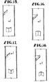
- plates 20 and 30 preferably have a generally planar configuration.
- the baffle plates may be convex and arcuate, as seen in Fig.16 the baffle plates may be concave and arcuate, as seen in Fig.17, the baffle plates may be convex and V-shaped, as seen in Fig.18 the baffle plates may be concave and V-shaped.
- the static mixer of the present invention is particularly notable in that achieves this mixing with a minimum pressure drop and across a wide range of flow rates and ratios of fluids and additives.
- the relative simple design of the baffle members used in the mixers requires a minimum amount of material and yet is stable and resistant to vibrations that can occur as a result of turbulent fluid flow.
- the design of the vortex mixer of the present invention reduces the sensitivity of the mixer to density differences between the main fluid stream and the additive, even at low flow rates and velocities where the Froude-number is extremely small and even small density differences would normally reduce the mixing efficiency or prevent any mixing from occurring.
- This can be a particular problem in conventional mixer designs when fluids of different densities, such as hot and cold air, hot and cold water, water and an aqueous salt solution or hydrocarbons of different densities, are flowing in straight horizontal flow channels and form stable separate flow layers of fluid.
- baffle member mixer in other less preferred embodiments, only a single baffle member or three or more baffle members may be used.
- baffle members are preferably spaced apart in the fluid flow direction, with each baffle member preferably being offset about the periphery of the conduit from each adjacent baffle member. The offset may be 90 degrees, as described with respect to the two baffle member embodiment, or some other selected angle.
- the invention is applicable to generally enclosed cylindrical conduits such as pipes and tubes and the like.
- the invention is also applicable to reclining and/or generally horizontally extending conduits which are not completely enclosed and have an opening, preferably a longitudinally extending opening, at the upper portions thereof.
- the conduit might by in the form of a horizontally extending ditch or trough or a semicircular piece of pipe having fluids which are moving therealong in a generally horizontal direction.
- the mixer may generally simply comprise a relatively short conduit having respective ends which are spaced a short distance beyond said first and second locations so that the mixer may be easily installed and/or removed for maintenance or periodic cleaning.
Landscapes
- Chemical & Material Sciences (AREA)
- Chemical Kinetics & Catalysis (AREA)
- Dispersion Chemistry (AREA)
Abstract
Description
- The present application relates generally to static fluid mixers and particularly to static mixers which are useful in generating fluid mixing vortices. The application also relates to methods for mixing fluids using such static mixers.
- Static mixers positioned within pipes or other conduits are used in a variety of applications to facilitate mixing of one or more fluid streams flowing within the conduits. For example, static mixers are used to cause a homogenous distribution of a gas or solid particles within a liquid stream, for mixing of two or more gas or liquid streams, and for mixing a single fluid stream to cause a more uniform distribution of temperature, velocity or other fluid properties.
- Certain types of static mixers, known as vortex mixers, are specifically designed to cause mixing by creating swirling vortices of fluid. Examples of such vortex mixers are shown in U.S. Patent No.4,307,697 to Ong, U.S. Patent No.5,330,267 to Tauscher, U.S. Patent No. 5,456,533 to Streiff et al., U.S. Patent Nos.4,929,088 and 4,981,368 to Smith, U.S. Patent No.5,489,153, and U.S. Patent No.5,813,762. Another example of a static mixer is shown in U.S. Patent No.5,758,967 to King, disclosing a stationary material mixing apparatus which includes a plurality of mixing elements characterized as having no edges perpendicular to the longitude axis. These mixing elements are connected, along a portion of the peripheral edges thereof, to the inner surface of the conduit.
- It is generally desirable for a vortex mixer to provide both a short mixing flow path and a small pressure loss under a variety of different flow conditions and fluid compositions. In addition to achieving high efficiency, it is also desirable for the vortex mixer to be of simple, yet durable, construction for ease of fabrication and reduced cost. The above-referenced vortex mixers meet these objectives to varying degrees; however, the need for an improved vortex mixer continues.
- It is an object of this invention to provide a static mixer that is capable of providing high mixing efficiency across a range of different fluid flow rates so that the mixer may be used in a variety of different applications.
- It is an object of this invention to provide a static mixer that provides high mixing efficiency for two or more substances, such as gas and liquid streams or solid particles and fluid streams, flowing within a conduit across a wide range of ratios of one substance to the other(s) so that the mixer is useful in many different applications.
- It is another object of this invention to provide a static mixer that achieves a high degree of mixing while causing only a relatively low pressure drop so that energy losses can be maintained within preselected limits.
- It is yet another object of this invention to provide a static mixer that is constructed to impede the collection of fibers or other solid particles on surfaces of the mixer so that the opportunity for clogging of the conduit is minimized when fluids containing fibers or solid particles are flowing through the conduit.
- It is a further object of this invention to provide a static mixer that is of a simple configuration and which is made from a minimum amount of material so that low fabrication and manufacturing costs can be obtained.
- As a corollary to the preceding object, it is a still further object to provide a static mixer that has a strong and stable construction so that it able to resist vibrations and fluid forces with minimal risk of failure.
- To achieve these and other related objects of the invention, a static mixer is provided which, in the preferred embodiment, uses only two baffle members positioned within a preselected length of conduit, one baffle member being positioned downstream from and at approximately a 90 degree offset from the other baffle member. Each baffle member is constructed in a manner to create a pair of counter-rotating vortices that are able to spread across the entire cross section of the conduit. Because of the offset baffle members, the static mixer produces mixing distribution in two main directions across the cross section of fluid flow, further contributing to homogenous mixing along a relatively short length of conduit and with a minimum of pressure drop.
- Specifically in one broad aspect, the invention provides a static fluid mixer that comprises an elongated fluid flow conduit having a centrally located longitudinally extending axis and an inner generally cylindrical wall extending around said axis and defining a fluid flow path within the conduit which extends along said central axis. Also the mixer includes a first elongated inclined baffle member positioned in said fluid flow path at a first location in said conduit and a second elongated inclined baffle member positioned in said fluid flow path at a second location in said conduit. The second location is offset circumferentially from the first location and the same is spaced longitudinally of the conduit from said first location. The arrangement of the baffle members is such that the mixer includes no additional baffle members which are aligned either circumferentially or longitudinally with either the first baffle member or the second baffle member.
- In another broad aspect, the invention provides a static fluid mixer comprising an elongated fluid flow conduit having a centrally located longitudinally extending axis and an inner generally cylindrical wall extending around said axis and defining a fluid flow path within the conduit which extends along said central axis. The mixer includes a first elongated inclined baffle member positioned in said fluid flow path at a first location in said conduit. The first baffle member is in the form of a plate having an upstream end, a downstream end and a longitudinal axis. The upstream end of the first baffle member is spaced radially from the wall a first distance which is less than a radius of the conduit, and the downstream end of the first baffle member is spaced radially from the conduit a second distance which is greater than said first distance.
- The mixer further includes a second elongated inclined baffle member positioned in said fluid flow path at a second location in said conduit. The second baffle member also is preferably in the form of a plate having an upstream end, a downstream end and a longitudinal axis. The upstream end of the second baffle member is spaced radially from the wall a third distance which is less than the radius of the conduit, and the downstream end of the first baffle member is spaced radially from the wall a fourth distance which is greater than said third distance. Preferably the second and fourth distances are such that the baffle members span approximately 70 percent of the diameter of the conduit. It is also preferred that the first and third distances comprise approximately 4 percent of the diameter of the conduit. The second location in the conduit is preferably offset circumferentially from the first location and spaced longitudinally of the conduit a fifth distance from said first location.
- The mixer may also include a mounting element for each of said baffle members. Preferably these mounting elements may extend radially of the conduit between a downstream face of a respective baffle and said wall. Ideally, the mounting elements may each be in the form of a member having an edge which contacts the wall of the conduit along a line which is essentially parallel with the central axis. Alternatively at least one of the mounting elements may be in the form of a sparger pipe.
- In a preferred form of the invention, the baffle members are of essentially the same shape, the first and third distances are essentially the same, and the second and fourth distances are essentially the same. Ideally, the members may be plates which are trapezoidal in shape. Ideally, the first and third distances are sufficiently large to permit portions of the fluid flowing through the conduit to pass between the upstream ends of the baffle members and the wall.
- In yet another preferred aspect of the invention, the downstream ends of the baffle plate members may have laterally spaced corners which are arranged to create counter-rotating vortices in the fluid flowing through the conduit. This arrangement facilitates thorough mixing of the materials flowing through the conduit.
- In another preferred form of the invention, the longitudinal distance between the first and second locations where the baffle members are positioned should be in the range of from approximately 2 times to approximately 10 times greater than the radius of the conduit. Ideally, such longitudinal distance may be approximately 4 times larger than said radius.
- Preferably, the baffle members may be offset circumferentially approximately 90° apart. In addition, in accordance with another preferred aspect of the invention, a longitudinal axis of each of the baffle members may be inclined at an angle in the range of from about 20 to about 60 degrees relative to the central axis of the conduit. Even more preferably, the longitudinal axes of the baffle members may be inclined at an angle in the range of from about 30 to about 50 degrees relative to the central axis of the conduit. Ideally, the longitudinal axes of the baffle members may each be inclined at an angle of about 35 degrees relative to the central axis of the conduit. In accordance with another preferred aspect of the invention, the upstream ends of the baffle members may be inclined at an angle of about 90 degrees relative to said axis.
- The baffle members may ideally be plates which are trapezoidal in shape with downstream ends which are smaller than the upstream ends. In accordance with the principles and concepts of the invention, the baffle plates may have any one of a variety of shapes and configurations. That is to say, the members may be plates which are essentially planar in transverse cross-sectional configuration. Alternatively, the members may be essentially non-planar in transverse cross-sectional configuration, essentially concave in transverse cross-sectional configuration, essentially convex in transverse cross-sectional configuration, or essentially V-shaped in transverse cross-sectional configuration. The baffle members may also include a hollow internal or external passageway providing a flow path for introducing an additive into a flow of fluids passing through the conduit. Alternatively, the baffle members may be in the form of porous and/or foraminous plates.
- The invention further provides a method of mixing one or more fluid streams comprising providing a static fluid mixer as described above and causing one or more fluid streams to flow along the fluid flow path defined by the conduit. The invention also provides a method of mixing solid particles with one or more fluid streams comprising providing a static fluid mixer as described above and causing a stream of solid particles and one or more fluid streams to flow along the fluid flow path defined by the conduit.
-
- FIGURE 1 is an isometric view, partly in cross-section, illustrating the internal components of a static mixer which embodies the principles and concepts of the invention;
- FIGURE 2 is a front elevational view of the static mixer of Fig. 1;
- FIGURE 3 is a cross-sectional view taken along line 3-3 of Fig. 2;
- FIGURE 4 is a front elevational view of another static mixer which embodies the principles and concepts of the invention, but with a different baffle configuration than the mixer of Figs. 1, 2 and 3;
- FIGURE 5 is a cross-sectional view taken along line 5-5 of Fig. 4;
- FIGURE 6 is an elevational cross-sectional view showing a foraminous baffle member;
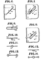
- FIGURES 7 through 14 are views showing a variety of useful configurations for baffle members which include sparger pipes and the like; and
- FIGURES 15 through 18 are elevational views showing static mixers of the invention with a variety of alternatively shaped baffle members.
-
- Referring now to the drawings in greater detail, and initially to FIGS. 1-3, a static fluid mixer which embodies the concepts and principles of the invention is identified by the
reference numeral 10.Mixer 10 includes an elongatedfluid flow conduit 12 having a centrally located longitudinally extendingaxis 14 and an inner generallycylindrical wall 16 extending aroundaxis 14.Conduit 12 defines afluid flow path 18 therewithin. An elongated inclined baffle member in the form ofplate 20 is positioned inflow path 18 at alocation 22 onwall 16.Plate 20 has anupstream end 24, adownstream end 26 and a longitudinal axis 28.Upstream end 24 is preferably spaced radially a distance D1 fromlocation 22 onwall 16. As can be seen in the drawings, distance D1 is generally less than the radius ofconduit 12. For that matter, end 24 may be positioned in contact withwall 16 with adequate results if such configuration is desirable. Sinceplate 20 projects acrossflow path 18, it is clear thatdownstream end 26 will be spaced radially from location 22 a distance D2 which is greater than distance D1. - Another elongated inclined baffle member in the form of a
plate 30 is positioned inflow path 18 at alocation 32 onwall 16.Plate 30 has anupstream end 34, adownstream end 36 and alongitudinal axis 38.Upstream end 34 is also preferably spaced radially fromlocation 32 on wall 16 a distance D3 which again is less than the radius ofconduit 12.Downstream end 36 is spaced radially from location 32 a distance D4 which is greater than distance D3. As can be seen viewing Fig. 3,plates - As can be seen in Fig. 2,
locations plates locations plates axis 14, preferably at an angle of about 90°; however, the desired offset angle may be more or less than 90° as may be determined empirically depending upon the nature of the fluid to be mixed. The distance D5 betweenlocations conduit 12. Ideally, the distance D5 should be about 4 times as large as the internal radius ofconduit 12. - Ideally, in accordance with the concepts and principles of the invention,
baffle plates flow path 18 and thereby throughconduit 12 to pass between upstream ends 24 and 34 andwall 16. This may prevent eddy currents and dead spots from developing behindplates -
Plates conduit 12. Ideally this dimension L should be such that the plates span about 70 percent of the diameter ofconduit 12. Moreover,plates axis 14. Even more preferably this angle of inclination may be within the range of from about 30 to about 50 degrees. Ideally this angle of inclination may be about 35 degrees. As can be seen from Figs. 3 and 4, the upstream ends 24 and 34 ofplates axis 14. - With reference particularly to Figs 1 through 3, it is also preferred that the downstream ends 26 and 36 of
plates corners 80 to create counter-rotating vortices 40 in the fluid passing throughconduit 12 alongpath 18. These vortices 40 work together to insure thorough mixing of the materials to be mixed throughout the entire extent of the interior ofconduit 12. -
Baffle plates plates conduit 12 betweenwall 16 and the respective downstream faces 64 and 66 ofplates plates respective edges contact wall 16 on a line which extends longitudinally ofconduit 12 alongflow path 18.Braces conduit wall 16 and faces 64 and 66 of thebaffle members braces braces conduit wall 16, the braces may just as well be attached to a ring structure that is inserted into theconduit 16 and is in turn affixed to the conduit wall by friction or other suitable means. An advantage of such a ring structure is it can be readily removed or replaced and can be used to quickly retrofit an existing conduit. - The
conduit 12 in which thebaffle members sparger pipe 85 may also be used as a mounting element for one or more of the baffle members as shown in Figs. 7-10. - With reference to Figs. 5 and 6, another embodiment of the invention is shown. In this embodiment, the arrangement is essentially the same as the embodiment of Figs. 1, 2 and 3, except that the upstream ends 46 and 48 of the baffle plates are arcuate and have a configuration which corresponds generally with the curvature of
wall 16. Accordingly,arcuate slots wall 16 and the arcuate ends 46 and 48. As before,slots conduit 12 to pass between ends 46 and 48 andwall 16. Preferably, to accomplish this purpose, the width ofslots conduit 12. - Although other known vortex static mixers are known to employ two or more baffle members at each of multiple locations along the axial length of the conduit, the present invention is directed to the use of only a single baffle member at each of two locations spaced a preselected distance apart in the direction of fluid flow within the conduit, and offset a preselected degree along the conduit wall in the transverse direction. This arrangement of baffle members allows a distribution of inhomogeneity over the entire cross section of conduit in a first main mixing direction as the fluid stream encounters the first baffle member, followed by distribution of the inhomogeneity over the entire cross section of the conduit in a second main direction as the fluid stream encounters the second baffle member. By orienting the baffle members with an approximately 90 degree offset, the first and second main mixing directions are similarly offset so that more complete and uniform mixing can occur with resulting increases in homogeneity. In addition, the use of only a single baffle member at each location facilitates uniform mixing across the entire conduit cross section by allowing the two counter-rotating vortices generated by each baffle member to expand across the entire cross section of the conduit. The use of multiple baffle members at each location might otherwise cause maldistribution of the fluid stream as a result of the production of multiple, interfering vortices.
- Sparger pipes used for introducing or dosing additives, such as additional fluid streams or substances, are preferably positioned so that they do not interfere with the counter-rotating vortices formed by the baffle members. Sparger pipes may preferably be located upstream from, or at, the upstream baffle member so that the additives are introduced upstream from the baffle member, at one or more locations along the upstream face of the baffle member, or even along the downstream face of the baffle member so that a portion of the fluid flowing along the flow path flows around the outside of the baffle member whilst another portion is introduced downstream of the baffle member. In applications where the additive fluid and the main fluid stream have substantially different densities, it may be particularly desirable to dose the additive fluid at and along the surface of the baffle member so that the fluids are immediately mixed together, thereby reducing the influence of the density difference on the mixing performance. Examples of different dosing structures which may be employed in connection with the present invention are illustrated in Figs.7 through 14.
- In this latter regard, Fig.9 illustrates a particularly preferred example of a dosing structure comprising a
sparger pipe 85. In Fig.9sparger pipe 85 lies on the downstream face 301 of abaffle member 300 which is in the form of a plate.Sparger pipe 85 may be affixed to face 301 by welding or the like. With this arrangement,sparger pipe 85 may provide a mounting element forbaffle plate 300. In Fig.11, thesparger pipe 85 is positioned centrally in the baffle plate. The structure of Fig.12 is similar to the structure of Fig.11, except that in thiscase sparger pipe 85 includes half round pipe portion that is closed by the baffle plate. The structure of Fig.13 is again similar to the structure of Fig.11, except that in this case twosparger pipes 85 are included at the edges of the baffle plate. In Fig. 14, the Fig.11 structure is combined with the Fig.13 structure. - With reference to Figs.7 and 8, the
baffle member 350 is hollow and provides aconduit 351 for fluid to flow therethrough.Sparger pipe 85 is inserted intoconduit 351 and may be affixed to bafflemember 350 by welding or the like. Again, as can be seen in Fig.7,sparger pipe 85 may serve as a mounting element for attachingbaffle member 350 to wall 16. In Fig.9, the construction is similar to the structure of Figs. 7 and 8, except that in this case thesparger pipe 85 is attached to the downstream face ofbaffle member 350. - The
baffle member 500 shown in Fig.6 is similar to thebaffle plates downstream face 502 of theplate 500 and allow a portion of fluid flowing along the flow path through thebaffle member 500 while another portion of the fluid flows around the outside of thebaffle member 500. - Preferably, if a sparger pipe is employed, the same should be located at an upstream baffle member. A particular advantage of using a single sparger pipe at the upstream baffle location is that such an arrangement allow the entire additive to be dosed at a single location rather than having to be divided into multiple, equal parts for distribution among a plurality of baffle members as in prior constructions. In addition, because the pressure at the backside of the inclined baffle member is lower than at the front side, the upstream end of the baffle member presents a preferred location for dosing of an additive. The pressure differential causes an increase in the velocity of the main fluid stream, increases the inertial force and Froude-number, and reduces the influence that the density difference between the main fluid stream and the additive has on the degree of homogeneity achieved. As a result, in this area of pressure differential there is an immediate, increased dilution effect on the additive by the main stream.
- As shown in Figs.1 through 5,
plates - Because the mixing process is normally within a distance of one to three times the conduit diameter downstream from the downstream baffle member, and the distance of separation between the baffle members is on the order of one to five times the conduit diameter, homogenous mixing can occur within a distance of two to eight times the conduit diameter, and normally three to five times the conduit diameter. In addition to providing effective mixing along a relative short length of conduit, the static mixer of the present invention is particularly notable in that achieves this mixing with a minimum pressure drop and across a wide range of flow rates and ratios of fluids and additives. The relative simple design of the baffle members used in the mixers requires a minimum amount of material and yet is stable and resistant to vibrations that can occur as a result of turbulent fluid flow.
- The design of the vortex mixer of the present invention reduces the sensitivity of the mixer to density differences between the main fluid stream and the additive, even at low flow rates and velocities where the Froude-number is extremely small and even small density differences would normally reduce the mixing efficiency or prevent any mixing from occurring. This can be a particular problem in conventional mixer designs when fluids of different densities, such as hot and cold air, hot and cold water, water and an aqueous salt solution or hydrocarbons of different densities, are flowing in straight horizontal flow channels and form stable separate flow layers of fluid.
- Although the invention has been described with respect to a two baffle member mixer, in other less preferred embodiments, only a single baffle member or three or more baffle members may be used. When multiple baffle members are used, they are preferably spaced apart in the fluid flow direction, with each baffle member preferably being offset about the periphery of the conduit from each adjacent baffle member. The offset may be 90 degrees, as described with respect to the two baffle member embodiment, or some other selected angle.
- The invention is applicable to generally enclosed cylindrical conduits such as pipes and tubes and the like. The invention is also applicable to reclining and/or generally horizontally extending conduits which are not completely enclosed and have an opening, preferably a longitudinally extending opening, at the upper portions thereof. For example, the conduit might by in the form of a horizontally extending ditch or trough or a semicircular piece of pipe having fluids which are moving therealong in a generally horizontal direction. In further accordance with the invention, the mixer may generally simply comprise a relatively short conduit having respective ends which are spaced a short distance beyond said first and second locations so that the mixer may be easily installed and/or removed for maintenance or periodic cleaning.
Claims (42)
- A static fluid mixer comprising: an elongate fluid flow conduit (12) having a centrally located longitudinally extending axis (14) and an inner generally cylindrical wall (16) extending around said axis and defining a fluid flow path (18) within the conduit which extends along said central axis; a first elongate inclined baffle member (20) positioned in said fluid flow path and connected to said wall at a first location (22) in said conduit; and a second elongate inclined baffle member (30) positioned in said fluid flow path and connected to said wall at a second location (32) in said conduit,
characterized by said first elongate baffle member having an upstream end (24), a downstream end (26) and a longitudinal axis (28), said upstream end of the first baffle member being spaced radially from the first location a first distance (D1) which is less than a radius of the conduit, said downstream end of the first baffle member being spaced radially from the first location a second distance (D2) which is greater than said first distance (D1); and said second elongate baffle member (30) having an upstream end (34), a downstream end (36) and a longitudinal axis (38), said upstream end of the second elongate baffle member being spaced radially from the second location a third distance (D3) which is less than said radius of the conduit, said downstream end of the second elongate baffle member being spaced radially from the second location a fourth distance (D4) which is greater than said third distance (D3), said second location being offset circumferentially from said first location and spaced longitudinally of the conduit a fifth distance (D5) from said first location. - A static fluid mixer as set forth in claim 1, wherein the downstream ends of said baffle members have laterally spaced corners (80) which are arranged to create counter-rotating vortices (40) in the fluid flowing through the conduit.
- A static fluid mixer as set forth in claim 2, said baffle members having a series of peripheral edges which include said upstream end, said downstream end, and a pair of laterally spaced side edges, said baffle members being positioned with said downstream ends, said side edges and said external corners all spaced from said inner surface of said cylindrical wall whereby at least a portion of the fluid flowing along said flow path flows around the outside of each baffle member between the corners and the wall.
- A static fluid mixer as set forth in claim 1, wherein the arrangement of said baffle members is such that said mixer includes no additional baffle members which are aligned either circumferentially or longitudinally with either said first baffle member or said second baffle member.
- A static fluid mixer as set forth in claim 1, or claim 3, or claim 4, wherein said baffle members (20, 30) comprise plates that are of essentially the same shape.
- A mixer as set forth in claim 4, or claim 5, wherein said baffle members each comprise plates.
- A static fluid mixer as set forth in claim 1, or claim 5, wherein said first and third distances (D1, D3) are essentially the same.
- A static fluid mixer as set forth in claim 1, or claim 7, wherein said second and fourth distances (D2, D4) are essentially the same.
- A static fluid mixer as set forth in claim 1, wherein said fifth distance (D5) is in the range of from about 2 to about 10 times larger than said radius.
- A static fluid mixer as set forth in claim 1, wherein said fifth distance (D5) is approximately 4 times larger than said radius.
- A static fluid mixer as set forth in claim 1, or claim 3, wherein said first and second locations are offset approximately 90° apart about a circumference of the wall (16).
- A static fluid mixer as set forth in claim 1, or claim 3, wherein said first and third distances (D1, D3) are sufficiently large to permit portions of the fluid flowing through the conduit to pass between said upstream ends and said wall.
- A static fluid mixer as set forth in claim 1, or claim 3, wherein said longitudinal axis of said first baffle member is inclined at an angle in the range of from 20 to 60 degrees relative to said central axis.
- A static fluid mixer as set forth in claim 1, or claim 3, wherein each of said baffle members has a longitudinal axis (28, 38) which is inclined at an angle in the range of from 20 to 60 degrees relative to said central.
- A static fluid mixer as set forth in claim 13, or claim 14, wherein said angle lies in the range of from 30 to 50 degrees relative to said central axis.
- A static fluid mixer as set forth in claim 15, wherein said angle is about 35 degrees relative to said central axis.
- A static fluid mixer as set forth in claim 1, or claim 3, wherein the upstream ends of said baffle members are inclined at an angle of about 90 degrees relative to said central axis.
- A static fluid mixer as set forth in claim 1, or claim 3, wherein said baffle members are trapezoidal in shape with said downstream ends being smaller than the upstream ends.
- A static fluid mixer as set forth in claim 1, wherein said baffle members are plates which are essentially planar in transverse cross-sectional configuration.
- A static fluid mixer as set forth in claim 1, wherein said baffle members are essentially non-planar in transverse cross-sectional configuration.
- A static fluid mixer as set forth in claim 1, wherein said baffle members are essentially concave in transverse cross-sectional configuration.
- A static fluid mixer as set forth in claim 1, wherein said baffle members are essentially convex in transverse cross-sectional configuration.
- A static fluid mixer as set forth in claim 1, wherein said baffle members are essentially V-shaped in transverse cross-sectional configuration.
- A static fluid mixer as set forth in claim 1, or claim 3, comprising a mounting element (60, 62) for each of said baffle members, each said element extending radially between a downstream surface (64, 66) of a respective baffle member and said cylindrical wall.
- A static fluid mixer as set forth in claim 24, wherein each element is generally in the form of a plate having an edge (68, 70) which contacts said downstream surface on a line which extends longitudinally of said conduit.
- A static mixer as set forth in claim 1, wherein the upstream ends of the baffle members are arcuate.
- A static mixer as set forth in claim 25, wherein the curvature of the arcuate upstream ends of the baffle members essentially corresponds with the curvature of the inner cylindrical wall of the conduit, whereby an arcuate slot (50, 52) is presented between said upstream ends and said wall.
- A static fluid mixer as set forth in claim 1, or claim 3, wherein at least one of said baffle members includes a hollow passageway (351) therein providing a flow path for introducing an additive into a flow of fluids passing through said conduit.
- A static fluid mixer as set forth in claim 24, wherein at least one of said mounting elements comprises a sparger pipe (85).
- A static fluid mixer as set forth in claim 28, wherein the mounting element for said at least one baffle member comprises a sparger pipe (85) which communicates with said passageway.
- A static fluid mixer as set forth in claim 1, or claim 3, wherein at least one of said baffle members has a longitudinal dimension that is sufficiently long to position the downstream end thereof on the opposite side of the central axis from the upstream side.
- A static fluid mixer as set forth in claim 1, or claim 3, wherein each of said baffle members has a longitudinal dimension that is sufficiently long to position the downstream end thereof on the opposite side of the central axis from the upstream side.
- A static fluid mixer as set forth in claim 31 or claim 32, wherein said longitudinal dimension spans approximately 70 percent of the diameter of the conduit.
- A static mixer as set forth in claim 27, wherein said slot has a width which is approximately 4 percent of the diameter of the conduit (12).
- A static fluid mixer as set forth in claim 1, or claim 3, wherein at least one of said baffle members comprises a sheet having perforations (501) which extend therethrough.
- A static fluid mixer as set forth in claim 1, wherein the said conduit is a relatively short conduit having respective ends which are spaced a short distance beyond said first and second locations.
- A static fluid mixer as set forth in claim 1, each baffle member (20, 30) having a series of peripheral edges including the upstream end (24, 34), the downstream end (26, 36), wherein the downstream end is elongate and laterally extending, and a pair of laterally spaced side edges which join with respective laterally spaced ends of said downstream end (26, 36) to present a pair of laterally spaced, external, counter-rotating eddy creating corners (80); said mixer further comprising a respective mounting structure for each of said baffle members (20, 30), each said structure including a connecting element (60, 62) extending inwardly from said wall (16) to a corresponding baffle member (20, 30), said baffle members (20, 30) being positioned with said downstream ends (26, 36), said side edges and said external corners (80) all spaced from the wall (16) whereby at least a portion of the fluid flowing along said flow path (18) flows around the outside of each baffle member (20, 30) between the corners (80) and the wall (16), and wherein at least one of said baffle members (20, 30) is trapezoidal in shape and the downstream end (26, 36) of said at least one baffle member (20, 30) is smaller in length than the upstream end (24, 34) thereof.
- Use of a vortex mixer as set forth in any one of the preceding claims 1 - 37, for mixing fluid streams.
- Use of a vortex mixer as set forth in any one of the preceding claims 1 - 37, for mixing solid particles with one or more fluid streams.
- A method of mixing a first fluid stream with a least one further stream capable of mixing therewith in a conduit, wherein the method comprises, providing a static mixer as set forth in any one of claims 1 - 37, as part of the conduit, and arranged such that a first baffle member and a second baffle member are disposed at spaced locations within the intended flow path, introducing the streams to be mixed to said flow path, and causing the streams to be subjected to successive counter-rotating vortices by passage over said first baffle member and said second baffle member, whereby uniform mixing is facilitated.
- A method according to claim 40, wherein the fluid streams are passed over both the first and second baffle members within a distance of from one to five times the diameter of the flow path as defined by the conduit.
- A method according to claim 40, wherein the streams are mixed within a flow path having a distance with respect to the second (downstream) baffle within the range of from one to three times the diameter of the flow path defined by the conduit.
Applications Claiming Priority (3)
| Application Number | Priority Date | Filing Date | Title |
|---|---|---|---|
| US12994699P | 1999-04-19 | 1999-04-19 | |
| US129946P | 1999-04-19 | ||
| PCT/US2000/010586 WO2000062915A1 (en) | 1999-04-19 | 2000-04-19 | Vortex static mixer and method employing same |
Publications (3)
| Publication Number | Publication Date |
|---|---|
| EP1178859A1 EP1178859A1 (en) | 2002-02-13 |
| EP1178859A4 EP1178859A4 (en) | 2003-02-19 |
| EP1178859B1 true EP1178859B1 (en) | 2005-07-13 |
Family
ID=22442339
Family Applications (1)
| Application Number | Title | Priority Date | Filing Date |
|---|---|---|---|
| EP00930114A Expired - Lifetime EP1178859B1 (en) | 1999-04-19 | 2000-04-19 | Vortex static mixer and method employing same |
Country Status (10)
| Country | Link |
|---|---|
| US (2) | US6604850B1 (en) |
| EP (1) | EP1178859B1 (en) |
| AR (1) | AR023745A1 (en) |
| AT (1) | ATE299392T1 (en) |
| AU (1) | AU4799200A (en) |
| CA (1) | CA2370778C (en) |
| DE (1) | DE60021263T2 (en) |
| ES (1) | ES2244441T3 (en) |
| TW (1) | TW486380B (en) |
| WO (1) | WO2000062915A1 (en) |
Families Citing this family (39)
| Publication number | Priority date | Publication date | Assignee | Title |
|---|---|---|---|---|
| AU782505B2 (en) * | 2000-05-05 | 2005-08-04 | Rakesh Kumar Aggarwal | Mixer and method for mixing liquids or a solid and a liquid |
| EP1339499A1 (en) * | 2000-05-05 | 2003-09-03 | Rakesh Kumar Aggarwal | Mixer and method for mixing liquids or a solid and a liquid |
| DE50001550D1 (en) * | 2000-06-19 | 2003-04-30 | Balcke Duerr Energietech Gmbh | Mixer for mixing at least two gas flows or other Newtonian liquids |
| NO318636B1 (en) * | 2002-02-08 | 2005-04-18 | Norsk Hydro As | Device for transformation of gas / liquid stream into layered stream |
| DE10330023A1 (en) * | 2002-07-20 | 2004-02-05 | Alstom (Switzerland) Ltd. | Vortex generator used in the swirling and mixing of fuel/air mixtures in pre-mixing combustion chambers comprises an outlet opening for targeted introduction of a secondary flow into the core flow of the wake produced |
| WO2004096420A1 (en) * | 2003-04-28 | 2004-11-11 | Indigo Technologies Group Pty Ltd | Method and apparatus for mixing fluids for particle agglomeration |
| DE10334593B3 (en) * | 2003-07-28 | 2005-04-21 | Framatome Anp Gmbh | mixing system |
| DE502004006983D1 (en) * | 2003-08-26 | 2008-06-12 | Sulzer Chemtech Ag | Static mixer with polymorphic structure |
| CA2839738C (en) | 2004-09-10 | 2015-07-21 | M-I L.L.C. | Apparatus and method for homogenizing two or more fluids of different densities |
| DE102004055507A1 (en) * | 2004-11-17 | 2006-05-18 | Basf Ag | Process for the preparation of finely divided liquid-liquid formulations and apparatus for the preparation of finely divided liquid-liquid formulations |
| US7350963B2 (en) * | 2005-02-04 | 2008-04-01 | Hamilton Beach Brands, Inc. | Blender jar |
| US7556031B2 (en) | 2005-12-12 | 2009-07-07 | Global Sustainability Technologies, LLC | Device for enhancing fuel efficiency of and/or reducing emissions from internal combustion engines |
| US7412974B2 (en) * | 2005-12-12 | 2008-08-19 | Gas Gorilla, Llc | Device for enhancing fuel efficiency of internal combustion engines |
| US8517693B2 (en) | 2005-12-23 | 2013-08-27 | Exxonmobil Upstream Research Company | Multi-compressor string with multiple variable speed fluid drives |
| US8083156B2 (en) * | 2007-05-18 | 2011-12-27 | Urs Corporation | Dispersion lance and shield for dispersing a treating agent into a fluid stream |
| US8011601B2 (en) * | 2007-05-18 | 2011-09-06 | Urs Corporation | Dispersion lance for dispersing a treating agent into a fluid stream |
| US8147124B1 (en) * | 2009-10-09 | 2012-04-03 | Robert W Glanville | Static mixer |
| CA2777868C (en) * | 2009-11-25 | 2018-07-31 | Exxonmobil Upstream Research Company | Centrifugal wet gas compression or expansion with a slug suppressor and/or atomizer |
| US8347733B2 (en) * | 2010-10-25 | 2013-01-08 | Cameron International Corporation | Conditioner, apparatus and method |
| US9003895B2 (en) | 2010-10-25 | 2015-04-14 | Cameron International Corporation | Conditioner, apparatus and method |
| GB201100673D0 (en) * | 2011-01-15 | 2011-03-02 | Statiflo Internat Ltd | Static mixer assembly |
| US9347355B2 (en) * | 2011-09-08 | 2016-05-24 | Tenneco Automotive Operating Company Inc. | In-line flow diverter |
| US9726063B2 (en) | 2011-09-08 | 2017-08-08 | Tenneco Automotive Operating Company Inc. | In-line flow diverter |
| JP5835776B2 (en) * | 2012-05-21 | 2015-12-24 | 株式会社 ソルエース | Air diffuser |
| CA2887857C (en) * | 2012-10-11 | 2017-06-13 | Halliburton Energy Services, Inc. | Method and apparatus for mixing fluid flow in a wellbore using a static mixer |
| US9067183B2 (en) | 2013-04-03 | 2015-06-30 | Westfall Manufacturing Company | Static mixer |
| US20140301157A1 (en) * | 2013-04-03 | 2014-10-09 | Westfall Manufacturing Company | Static Mixer |
| US9221022B2 (en) | 2013-04-03 | 2015-12-29 | Westfall Manufacturing Company | Static mixer |
| DE102016124042A1 (en) * | 2016-12-12 | 2018-06-14 | Mitsubishi Hitachi Power Systems Europe Gmbh | Process and apparatus for flue gas treatment of flue gases fossil-fired steam power plants by means of an adsorbent |
| EP3568381A4 (en) * | 2017-01-15 | 2021-06-09 | Butler, Michael, George | Apparatuses and systems for and methods of generating and placing zero-slump-pumpable concrete |
| PT3852912T (en) * | 2018-09-20 | 2022-11-25 | Noram Eng And Constructors Ltd | Fluid mixing device |
| US10737227B2 (en) * | 2018-09-25 | 2020-08-11 | Westfall Manufacturing Company | Static mixer with curved fins |
| ES2767024B2 (en) | 2018-12-14 | 2021-09-17 | Univ Sevilla | VORTE GENERATOR DEVICE IN CHANNELS OR DUCTS |
| US11285448B1 (en) * | 2021-04-12 | 2022-03-29 | William J. Lund | Static mixer inserts and static mixers incorporating same |
| KR102396629B1 (en) | 2021-06-22 | 2022-05-10 | 삼성엔지니어링 주식회사 | Auto-agitating nozzle for construction 3d printer |
| KR102396630B1 (en) * | 2021-06-22 | 2022-05-10 | 삼성엔지니어링 주식회사 | Reinforcement extruding nozzle for construction 3d printer |
| KR20240134931A (en) | 2022-01-28 | 2024-09-10 | 아이커 시스템즈, 인크. | Fluid transfer module |
| EP4303436B1 (en) * | 2022-07-04 | 2026-01-28 | Wobben Properties GmbH | Wind turbine blade rotor blade and wind turbine |
| CN115611003B (en) * | 2022-10-26 | 2025-08-01 | 江苏师范大学 | Horizontal pipeline sedimentation preventing device, disassembly and assembly method and material conveying system |
Family Cites Families (12)
| Publication number | Priority date | Publication date | Assignee | Title |
|---|---|---|---|---|
| US3652061A (en) * | 1971-03-04 | 1972-03-28 | Dow Chemical Co | Interfacial surface generator and method of preparation thereof |
| JPS6027826B2 (en) | 1975-10-02 | 1985-07-01 | オン・シヤク・フ− | Vortex generation device for intake air-fuel mixture in internal combustion engine |
| DE3043239C2 (en) | 1980-11-15 | 1985-11-28 | Balcke-Dürr AG, 4030 Ratingen | Method and device for mixing at least two fluid partial flows |
| US4643584A (en) | 1985-09-11 | 1987-02-17 | Koch Engineering Company, Inc. | Motionless mixer |
| CH669336A5 (en) * | 1985-12-11 | 1989-03-15 | Sulzer Ag | |
| US4929088A (en) | 1988-07-27 | 1990-05-29 | Vortab Corporation | Static fluid flow mixing apparatus |
| US4981368A (en) | 1988-07-27 | 1991-01-01 | Vortab Corporation | Static fluid flow mixing method |
| DE4123161A1 (en) | 1991-07-12 | 1993-01-14 | Siemens Ag | STATIC MIXER |
| EP0526393B1 (en) | 1991-07-30 | 1996-08-28 | Sulzer Chemtech AG | mixing-in device |
| EP0546989B1 (en) | 1991-12-10 | 1995-11-15 | Sulzer Chemtech AG | Static mixing element with guiding faces |
| US5758967A (en) | 1993-04-19 | 1998-06-02 | Komax Systems, Inc. | Non-clogging motionless mixing apparatus |
| EP0800857B1 (en) * | 1996-04-12 | 2003-07-30 | Sulzer Chemtech AG | Mixer tube for low viscosity fluids |
-
2000
- 2000-04-19 WO PCT/US2000/010586 patent/WO2000062915A1/en not_active Ceased
- 2000-04-19 AR ARP000101835A patent/AR023745A1/en unknown
- 2000-04-19 ES ES00930114T patent/ES2244441T3/en not_active Expired - Lifetime
- 2000-04-19 AT AT00930114T patent/ATE299392T1/en not_active IP Right Cessation
- 2000-04-19 CA CA002370778A patent/CA2370778C/en not_active Expired - Lifetime
- 2000-04-19 TW TW089107404A patent/TW486380B/en active
- 2000-04-19 US US09/552,234 patent/US6604850B1/en not_active Expired - Lifetime
- 2000-04-19 DE DE60021263T patent/DE60021263T2/en not_active Expired - Lifetime
- 2000-04-19 EP EP00930114A patent/EP1178859B1/en not_active Expired - Lifetime
- 2000-04-19 AU AU47992/00A patent/AU4799200A/en not_active Abandoned
-
2001
- 2001-09-05 US US09/946,656 patent/US20020031046A1/en not_active Abandoned
Also Published As
| Publication number | Publication date |
|---|---|
| CA2370778A1 (en) | 2000-10-26 |
| TW486380B (en) | 2002-05-11 |
| EP1178859A1 (en) | 2002-02-13 |
| AU4799200A (en) | 2000-11-02 |
| AR023745A1 (en) | 2002-09-04 |
| ES2244441T3 (en) | 2005-12-16 |
| WO2000062915A1 (en) | 2000-10-26 |
| EP1178859A4 (en) | 2003-02-19 |
| DE60021263T2 (en) | 2006-04-27 |
| US6604850B1 (en) | 2003-08-12 |
| ATE299392T1 (en) | 2005-07-15 |
| US20020031046A1 (en) | 2002-03-14 |
| CA2370778C (en) | 2006-09-26 |
| DE60021263D1 (en) | 2005-08-18 |
Similar Documents
| Publication | Publication Date | Title |
|---|---|---|
| US6604850B1 (en) | Vortex static mixer | |
| EP0738373B1 (en) | Stationary material mixing apparatus | |
| JP3578355B2 (en) | Mixing device | |
| US6779786B2 (en) | Mixer for mixing at least two flows of gas or other newtonian liquids | |
| JP3174054B2 (en) | Static mixer | |
| KR100481930B1 (en) | Low Viscosity Fluid Mixer Tubes | |
| US4981368A (en) | Static fluid flow mixing method | |
| KR101379418B1 (en) | A static mixer | |
| US6623155B1 (en) | Static mixer | |
| AU755769B2 (en) | A swirling flashback arrestor | |
| EP1036588B1 (en) | Static mixing device | |
| US4179222A (en) | Flow turbulence generating and mixing device | |
| US20050190643A1 (en) | Arrangement for mixing of fluid streams | |
| CA2343561C (en) | Mixing element for a flange transition in a pipeline | |
| US20080277009A1 (en) | Multiple helical vortex baffle | |
| US7448794B2 (en) | Method for mixing fluid streams | |
| CA2350944C (en) | Mixer for mixing gases and other newtonian liquids | |
| US20040013032A1 (en) | Method and apparatus for injecting a chemical into a process upstream of an inline mixer | |
| EP2248577A1 (en) | Fluid mixing apparatus with injection lance | |
| CN211659741U (en) | Mixer containing porous annular cavity and inner extension pipe | |
| CA2221158C (en) | Static fluid flow mixing apparatus | |
| KR101913030B1 (en) | Static mixer and fluid mixing structure including the same | |
| JPH10314565A (en) | Fluid mixer | |
| JP3040942U (en) | Plastic static mixer | |
| CA1136613A (en) | Mixing duct having turbulence generating septum panels in overlapping divergent pairs |
Legal Events
| Date | Code | Title | Description |
|---|---|---|---|
| PUAI | Public reference made under article 153(3) epc to a published international application that has entered the european phase |
Free format text: ORIGINAL CODE: 0009012 |
|
| 17P | Request for examination filed |
Effective date: 20011113 |
|
| AK | Designated contracting states |
Kind code of ref document: A1 Designated state(s): AT BE CH CY DE DK ES FI FR GB GR IE IT LI LU MC NL PT SE |
|
| AX | Request for extension of the european patent |
Free format text: AL;LT;LV;MK;RO;SI |
|
| A4 | Supplementary search report drawn up and despatched |
Effective date: 20030108 |
|
| RIC1 | Information provided on ipc code assigned before grant |
Ipc: 7B 01F 5/06 B Ipc: 7B 01F 5/04 B Ipc: 7B 01F 5/00 A |
|
| RAP1 | Party data changed (applicant data changed or rights of an application transferred) |
Owner name: SULZER CHEMTECH AG |
|
| 17Q | First examination report despatched |
Effective date: 20040324 |
|
| GRAP | Despatch of communication of intention to grant a patent |
Free format text: ORIGINAL CODE: EPIDOSNIGR1 |
|
| GRAS | Grant fee paid |
Free format text: ORIGINAL CODE: EPIDOSNIGR3 |
|
| GRAA | (expected) grant |
Free format text: ORIGINAL CODE: 0009210 |
|
| AK | Designated contracting states |
Kind code of ref document: B1 Designated state(s): AT BE CH CY DE DK ES FI FR GB GR IE IT LI LU MC NL PT SE |
|
| PG25 | Lapsed in a contracting state [announced via postgrant information from national office to epo] |
Ref country code: AT Free format text: LAPSE BECAUSE OF FAILURE TO SUBMIT A TRANSLATION OF THE DESCRIPTION OR TO PAY THE FEE WITHIN THE PRESCRIBED TIME-LIMIT Effective date: 20050713 Ref country code: BE Free format text: LAPSE BECAUSE OF FAILURE TO SUBMIT A TRANSLATION OF THE DESCRIPTION OR TO PAY THE FEE WITHIN THE PRESCRIBED TIME-LIMIT Effective date: 20050713 Ref country code: FI Free format text: LAPSE BECAUSE OF FAILURE TO SUBMIT A TRANSLATION OF THE DESCRIPTION OR TO PAY THE FEE WITHIN THE PRESCRIBED TIME-LIMIT Effective date: 20050713 |
|
| REG | Reference to a national code |
Ref country code: GB Ref legal event code: FG4D |
|
| REG | Reference to a national code |
Ref country code: CH Ref legal event code: EP |
|
| REG | Reference to a national code |
Ref country code: IE Ref legal event code: FG4D |
|
| REF | Corresponds to: |
Ref document number: 60021263 Country of ref document: DE Date of ref document: 20050818 Kind code of ref document: P |
|
| PG25 | Lapsed in a contracting state [announced via postgrant information from national office to epo] |
Ref country code: DK Free format text: LAPSE BECAUSE OF FAILURE TO SUBMIT A TRANSLATION OF THE DESCRIPTION OR TO PAY THE FEE WITHIN THE PRESCRIBED TIME-LIMIT Effective date: 20051013 Ref country code: GR Free format text: LAPSE BECAUSE OF FAILURE TO SUBMIT A TRANSLATION OF THE DESCRIPTION OR TO PAY THE FEE WITHIN THE PRESCRIBED TIME-LIMIT Effective date: 20051013 Ref country code: SE Free format text: LAPSE BECAUSE OF FAILURE TO SUBMIT A TRANSLATION OF THE DESCRIPTION OR TO PAY THE FEE WITHIN THE PRESCRIBED TIME-LIMIT Effective date: 20051013 |
|
| REG | Reference to a national code |
Ref country code: CH Ref legal event code: NV Representative=s name: E. BLUM & CO. PATENTANWAELTE |
|
| REG | Reference to a national code |
Ref country code: ES Ref legal event code: FG2A Ref document number: 2244441 Country of ref document: ES Kind code of ref document: T3 |
|
| PG25 | Lapsed in a contracting state [announced via postgrant information from national office to epo] |
Ref country code: PT Free format text: LAPSE BECAUSE OF FAILURE TO SUBMIT A TRANSLATION OF THE DESCRIPTION OR TO PAY THE FEE WITHIN THE PRESCRIBED TIME-LIMIT Effective date: 20051219 |
|
| ET | Fr: translation filed | ||
| PG25 | Lapsed in a contracting state [announced via postgrant information from national office to epo] |
Ref country code: IE Free format text: LAPSE BECAUSE OF NON-PAYMENT OF DUE FEES Effective date: 20060419 |
|
| PG25 | Lapsed in a contracting state [announced via postgrant information from national office to epo] |
Ref country code: MC Free format text: LAPSE BECAUSE OF NON-PAYMENT OF DUE FEES Effective date: 20060430 |
|
| PLBE | No opposition filed within time limit |
Free format text: ORIGINAL CODE: 0009261 |
|
| STAA | Information on the status of an ep patent application or granted ep patent |
Free format text: STATUS: NO OPPOSITION FILED WITHIN TIME LIMIT |
|
| 26N | No opposition filed |
Effective date: 20060418 |
|
| REG | Reference to a national code |
Ref country code: IE Ref legal event code: MM4A |
|
| REG | Reference to a national code |
Ref country code: CH Ref legal event code: PFA Owner name: SULZER CHEMTECH AG Free format text: SULZER CHEMTECH AG#HEGIFELDSTRASSE 10#8404 WINTERTHUR (CH) -TRANSFER TO- SULZER CHEMTECH AG#HEGIFELDSTRASSE 10#8404 WINTERTHUR (CH) |
|
| PG25 | Lapsed in a contracting state [announced via postgrant information from national office to epo] |
Ref country code: LU Free format text: LAPSE BECAUSE OF NON-PAYMENT OF DUE FEES Effective date: 20060419 |
|
| PG25 | Lapsed in a contracting state [announced via postgrant information from national office to epo] |
Ref country code: CY Free format text: LAPSE BECAUSE OF FAILURE TO SUBMIT A TRANSLATION OF THE DESCRIPTION OR TO PAY THE FEE WITHIN THE PRESCRIBED TIME-LIMIT Effective date: 20050713 |
|
| REG | Reference to a national code |
Ref country code: CH Ref legal event code: PCOW Free format text: NEW ADDRESS: SULZERALLEE 48, 8404 WINTERTHUR (CH) Ref country code: CH Ref legal event code: NV Representative=s name: DR. GRAF AND PARTNER AG INTELLECTUAL PROPERTY, CH |
|
| REG | Reference to a national code |
Ref country code: FR Ref legal event code: PLFP Year of fee payment: 17 |
|
| REG | Reference to a national code |
Ref country code: FR Ref legal event code: PLFP Year of fee payment: 18 |
|
| REG | Reference to a national code |
Ref country code: DE Ref legal event code: R082 Ref document number: 60021263 Country of ref document: DE Representative=s name: PATENTANWAELTE HENKEL, BREUER & PARTNER, DE Ref country code: DE Ref legal event code: R082 Ref document number: 60021263 Country of ref document: DE Representative=s name: HENKEL, BREUER & PARTNER, DE |
|
| REG | Reference to a national code |
Ref country code: DE Ref legal event code: R082 Ref document number: 60021263 Country of ref document: DE Representative=s name: HENKEL, BREUER & PARTNER, DE |
|
| REG | Reference to a national code |
Ref country code: FR Ref legal event code: PLFP Year of fee payment: 19 |
|
| PGFP | Annual fee paid to national office [announced via postgrant information from national office to epo] |
Ref country code: NL Payment date: 20180418 Year of fee payment: 19 |
|
| PGFP | Annual fee paid to national office [announced via postgrant information from national office to epo] |
Ref country code: DE Payment date: 20180420 Year of fee payment: 19 Ref country code: CH Payment date: 20180419 Year of fee payment: 19 Ref country code: ES Payment date: 20180525 Year of fee payment: 19 |
|
| PGFP | Annual fee paid to national office [announced via postgrant information from national office to epo] |
Ref country code: FR Payment date: 20180420 Year of fee payment: 19 Ref country code: IT Payment date: 20180423 Year of fee payment: 19 |
|
| PGFP | Annual fee paid to national office [announced via postgrant information from national office to epo] |
Ref country code: GB Payment date: 20180418 Year of fee payment: 19 |
|
| REG | Reference to a national code |
Ref country code: DE Ref legal event code: R119 Ref document number: 60021263 Country of ref document: DE |
|
| REG | Reference to a national code |
Ref country code: CH Ref legal event code: PL |
|
| REG | Reference to a national code |
Ref country code: NL Ref legal event code: MM Effective date: 20190501 |
|
| GBPC | Gb: european patent ceased through non-payment of renewal fee |
Effective date: 20190419 |
|
| PG25 | Lapsed in a contracting state [announced via postgrant information from national office to epo] |
Ref country code: CH Free format text: LAPSE BECAUSE OF NON-PAYMENT OF DUE FEES Effective date: 20190430 Ref country code: DE Free format text: LAPSE BECAUSE OF NON-PAYMENT OF DUE FEES Effective date: 20191101 Ref country code: NL Free format text: LAPSE BECAUSE OF NON-PAYMENT OF DUE FEES Effective date: 20190501 Ref country code: LI Free format text: LAPSE BECAUSE OF NON-PAYMENT OF DUE FEES Effective date: 20190430 Ref country code: GB Free format text: LAPSE BECAUSE OF NON-PAYMENT OF DUE FEES Effective date: 20190419 |
|
| PG25 | Lapsed in a contracting state [announced via postgrant information from national office to epo] |
Ref country code: IT Free format text: LAPSE BECAUSE OF NON-PAYMENT OF DUE FEES Effective date: 20190419 |
|
| PG25 | Lapsed in a contracting state [announced via postgrant information from national office to epo] |
Ref country code: FR Free format text: LAPSE BECAUSE OF NON-PAYMENT OF DUE FEES Effective date: 20190430 |
|
| REG | Reference to a national code |
Ref country code: ES Ref legal event code: FD2A Effective date: 20200831 |
|
| PG25 | Lapsed in a contracting state [announced via postgrant information from national office to epo] |
Ref country code: ES Free format text: LAPSE BECAUSE OF NON-PAYMENT OF DUE FEES Effective date: 20190420 |