EP1178685A2 - Multi-point camera system - Google Patents
Multi-point camera system Download PDFInfo
- Publication number
- EP1178685A2 EP1178685A2 EP00307673A EP00307673A EP1178685A2 EP 1178685 A2 EP1178685 A2 EP 1178685A2 EP 00307673 A EP00307673 A EP 00307673A EP 00307673 A EP00307673 A EP 00307673A EP 1178685 A2 EP1178685 A2 EP 1178685A2
- Authority
- EP
- European Patent Office
- Prior art keywords
- monitor
- image recognition
- camera
- automatic focusing
- preset
- Prior art date
- Legal status (The legal status is an assumption and is not a legal conclusion. Google has not performed a legal analysis and makes no representation as to the accuracy of the status listed.)
- Withdrawn
Links
Images


Classifications
-
- H—ELECTRICITY
- H04—ELECTRIC COMMUNICATION TECHNIQUE
- H04N—PICTORIAL COMMUNICATION, e.g. TELEVISION
- H04N7/00—Television systems
- H04N7/18—Closed-circuit television [CCTV] systems, i.e. systems in which the video signal is not broadcast
- H04N7/188—Capturing isolated or intermittent images triggered by the occurrence of a predetermined event, e.g. an object reaching a predetermined position
Definitions
- the present invention relates to a camera system having a function of monitoring a plurality of view angles and positions and detecting an abnormal entrance from monitored images.
- a surveillance camera with a fixed monitor position for detecting an abnormal entrance by an image recognition process is disclosed in JP-A-9-276237. This monitor camera always takes an image at a fixed monitor position and any change in the image is checked by the image recognition process to detect an abnormal entrance.
- JP-A-8-139987 Another surveillance camera mounted with a pan/tilt driver unit and a preset unit is disclosed in JP-A-8-139987. This camera is set to take an image at a desired position, and pan, tilt, zoom and focus positions for that position are preset to control the camera monitor position in accordance with the preset values.
- An image recognition method is not disclosed in this publication.
- Products of a combination of a tripod head capable of panning and tilting and a zoom camera for monitoring a plurality of view angles and positions are known. However, although most of these products preset monitor positions and angle views to switch therebetween at high speed and monitor a wide image area, they cannot perform automatic recognition of a monitor object because an image recognition process is not incorporated.
- image recognition may become unstable each time switching occurs among a plurality of view angles and positions. Erroneous recognition may occur and an abnormal entrance cannot be detected reliably.
- a combination of an image recognition unit a zoom camera equipped with a pan/tilt driver unit for changing a camera monitor position is used to monitor a plurality of monitor positions.
- the monitor position is changed by using the pan/tilt unit, and an image recognition unit starts an image recognition process to reliably detect an abnormal entrance at the plurality of monitor positions, after a focus position adjustment by preset information (after completion of commanding to change the focus position to a preset position or stop at the preset position), after an automatic focusing operation (hereinafter called an AF operation), or after a combination of the focus position adjustment by the preset information and the automatic focusing operation.
- a combination of an image recognition unit a zoom camera equipped with a zoom mechanism for changing a camera monitor view angle is used to monitor a plurality of monitor positions, at least two monitor positions having different view angles.
- the camera monitor view angle is changed in accordance with preset information, and an image recognition unit starts an image recognition process to reliably detect an abnormal entrance at the plurality of monitor positions, after completion of changing to the present position or completion of an operation by the zoom mechanism, after completion of setting an in-focus state by the automatic focusing operation, or after a combination of the focus position adjustment by the preset information and the automatic focusing operation.
- the image recognition unit starts the image recognition process after the automatic focusing operation, at the same time when the automatic focusing operation starts, a timer is activated, if the in-focus state does not enter in a predetermined time lapse, the focus position is forcibly set to the preset position, and thereafter the image recognition unit starts the image recognition process to reliably detect an abnormal entrance at a plurality of monitor positions.
- Fig. 1 is a block diagram showing the structure of a multi-point surveillance camera system according to an embodiment of the invention.
- Fig. 2 shows an example of a GUI display screen of a controller.
- Fig. 3 is a flow chart illustrating an operation up to a start of an image recognition process.
- Fig. 4 shows an example of an image without any intruder.
- Fig. 5 shows an example of an image with an intruder near to the camera.
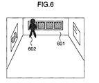
- Fig. 6 shows an example of an image with an intruder remote from the camera.
- Fig. 1 is a block diagram showing the structure of a multi-point surveillance camera system according to the embodiment of the invention.
- reference numeral 101 represents a camera.
- Reference numeral 102 represents an image recognition unit for calculating a change in an image by an image recognition process and detecting any intruder if any.
- Reference numeral 103 represents a pan/tilt driver unit for driving a pan/tilt mechanism of the camera.
- Reference numeral 104 represents a focus control unit for controlling a focus position in order to adjust the focal point.
- Reference numeral 105 represents a preset unit for storing pan, tilt, zoom and focus positions and a background image.
- Reference numeral 106 represents a control unit for performing a pan-tilt control, a zoom control and a preset operation.
- Reference numeral 107 represents a zoom driver unit for changing the size of a view angle.
- Fig. 2 shows an example of a GUI display screen of the control unit 106.
- the control unit 106 outputs a pan motion target position and a tilt motion target position e1 to the image recognition unit 102.
- the image recognition unit 102 supplies a pan/tilt motion target position a1 to the pan-tilt driver unit 103.
- the image recognition unit 102 stores the present pan/tilt position.
- the pan/tilt driver unit 103 outputs a drive control signal b1 to the camera 101 to change the pan and tilt positions and set the camera monitor position.
- the control device 106 For a zoom operation, as a user manipulates a zoom button 202, the control device 106 outputs a zoom position e4 to the image recognition unit 102.
- the image recognition unit 102 outputs a zoom position h to the zoom driver unit 107.
- the image recognition unit 102 stores the present zoom position.
- the zoom driver unit 107 outputs a zoom control signal i to the camera 101.
- the camera 101 drives its zoom mechanism to change the size of a view angle of an image.
- the camera 101 stops, the camera 101 outputs a camera motion stop signal c2 to the image recognition unit 102.
- An automatic focusing (AF) operation is executed by using the camera 101, the focus control unit 104 having the focus mechanism and the image recognition unit 102.
- the image recognition unit 102 confirms from the camera motion stop signal c2 that the camera motion stopped, it outputs an AF activation request signal f1 to the focus control unit 104.
- the focus control unit 104 outputs a focus drive amount signal d1 to the camera 101 so that the focus position of the camera is moved by an amount corresponding to the focus drive amount signal d1.
- the camera 101 outputs an image signal d2 to the focus control unit 104.
- an in-focus judgement process is executed.
- the focus control unit 104 outputs an focusing operation completion signal f2 and a focus position f3 to the image recognition unit 102.
- the image recognition unit 102 stores the present focus position.
- the image recognition unit 102 When the image recognition unit 102 confirms an in-focus state from the focusing operation completion signal f2, the image recognition unit 102 starts an image recognition process which always checks a change amount of a monitor image input through a lens of the camera 101 in accordance with the image signal c1 representative of the monitor image and detects an abnormal entrance if any.
- a user manipulates a preset number setting button 203 to designate a preset number "4". Then, the user manipulates a preset button 204.
- the control unit 106 outputs the preset number and a preset request e2 to the image recognition unit 102.
- the image recognition unit 102 always acquires camera information and outputs present camera pan, tilt, zoom (view angle) and focus positions, an input image, and a preset number g1 to the preset unit 105.
- the preset unit 105 stores the pan, tilt, zoom (view angle) and focus positions, and the input image (background image) corresponding to the preset number "4" in a memory region for the preset number "4".
- the control unit 106 outputs a multimonitor execute request e3 to the image recognition unit 102.
- the image recognition unit 102 outputs a preset data request g2 for a preset number "1" to the preset unit 105.
- the preset unit 105 outputs preset data g3 to the image recognition unit 102. If the preset data does not exist, empty data is output. If the preset data does not exist, the image recognition unit 102 outputs the preset data request g2 to the preset unit 105 by changing the preset number until the preset data is found. If the preset number exceeds the maximum preset number, an output of the preset data request g2 is terminated.
- the image recognition unit 102 outputs the pan/tilt motion target position a1 to the pan/tilt driver unit 103.
- the pan/tilt driver unit 103 outputs the drive control signal b1 to the camera 101 to change the camera monitor position through a pan/tilt operation.
- the image recognition unit 102 also outputs the zoom position h to the zoom driver unit 107.
- the image recognition unit 102 stores the present zoom position.
- the zoom driver unit 107 outputs the zoom control signal i to the camera 101.
- the camera 101 drives its zoom mechanism to change the size of a view angle of the monitor image.
- the camera 101 stops, the camera 101 outputs the camera motion stop signal c2 to the image recognition unit 102.
- the image recognition unit 102 confirms from the camera motion stop signal c2 that the camera motion stopped, it outputs a focus motion target position f4 to the focus control unit 104, in accordance with the preset focus position.
- the focus control unit 104 outputs the focus drive amount signal d1 to the camera 101 so that the focus position of the camera 101 is moved by an amount corresponding to the focus drive amount signal d1.
- the camera 101 outputs the image signal d2 to the focus control unit 104.
- the focus control unit 104 judges whether the focus is set to the in-focus state.
- the focus control unit 104 outputs the focusing operation completion signal f2 to the image recognition unit 102.
- the image recognition unit 102 When the image recognition unit 102 confirms an in-focus state from the focusing operation completion signal f2, the image recognition unit 102 starts an image recognition process to detect an abnormal entrance if any. If it is judged that the focus is not in the in-focus state, the image recognition unit 102 outputs the AF activation request signal f1 to the focus control unit 104. At the same time, a timer starts operating. The focus control unit 104 starts the AF operation and outputs the lens drive amount d1 to the camera 101. The camera 101 changes its focus position by an amount corresponding to the lens drive amount d1. The camera 101 outputs the image signal d2. In accordance with the image signal d2, the focus control unit 104 judges whether the focus is in the in-focus state.
- the focus control unit 104 outputs the in-focus operation completion signal f2 and the focus position f3 to the image recognition unit 102.
- the focus control unit 104 outputs the focus position to the camera 101 and continues the AF operation, until it is judged that the focus is in the in-focus state.
- the image recognition unit 102 stores the present focus position represented by the focus position f3.
- the image recognition unit 102 judges the in-focus state from the in-focus state operation completion signal f2.
- the in-focus judgment by the image recognition unit 102 is made in a predetermined time duration after the start of the AF operation as counted with the timer, and then the image recognition unit 102 starts the image recognition process to detect an abnormal entrance if any. If the in-focus judgement is not made in the predetermined time duration, the image recognition unit 102 outputs an AF forcible stop request f5 to the focus control unit 104.
- the focus control unit 104 stops the AF operation.
- the image recognition unit 102 again outputs the focus motion target position f4 to the focus control unit 104.
- the focus control unit 104 outputs the lens drive amount d1 to the camera 101.
- the camera 101 changes its focus position by an amount corresponding to the lens drive amount d1.
- the image recognition unit 102 starts the image recognition process to detect an abnormal entrance if any.
- An abnormal entrance is detected as in the following.
- An image difference calculated through a normalized correlation calculation between the preset background image and the present input image, and a calculated monitor object area and shape difference, are compared with judgement threshold values. If the image recognition results are in a range of the judgement threshold values (object area, shape and so on), while the image difference is more than a certain value, it is judged that there is an abnormal entrance.
- the image recognition unit 102 outputs the preset data request g2 for the next preset number to the preset unit 105 to execute the monitor operation for the next preset number and repeat the above-described operations.
- the image recognition process may be started after the camera is moved to the focus position corresponding to each preset position, without executing the AF operation.
- the camera can reliably follow a monitor object (including a moving object) or an obstacle in the image to be caused by an abnormal entrance, so that a monitor image having a good focusing state can be obtained and the image recognition precision can be improved.
- FIG. 3 is a flow chart illustrating the operation up to the start of an image recognition process.
- the camera monitor position such as the pan and tilt positions for each monitor position is set in accordance with preset camera position information.
- the lens focus position is set in accordance with information such as the view angle size corresponding to each preset monitor view angle and a lens focus position.
- Step 303 an AF operation timer is started.
- the AF operation starts. If the background image is a flat image with less edges such as a wall, it takes a long time to complete the AF operation, and at the worst the AF operation may not be completed. In such a case, the time-out of the timer occurs at Step 306.
- the focus position is again set to the preset lens focus position to move the focus position to that of the background image.
- the image recognition process starts at Step 309. In this manner, a delay of the start of the image recognition process is suppressed. If the in-focus state is set in the predetermined time duration, then the image recognition process starts at Step 309. In this manner, the image recognition process can start and an optimum monitor image can be obtained.
- Fig. 4 shows an example of an image without any intruder.
- the AF focus position is at a background image 401.
- a difference between an input monitor image and the preset background image is used for detecting an abnormal entrance. In this example, this difference is not detected and no abnormal entrance is detected.
- Fig. 5 shows an example of an image with an intruder near to the camera.
- Reference numeral 501 represents the background image
- reference numeral 502 represents an intruder image.
- the AF focus position is at the intruder image 502. Therefore the background image 501 is an out-of-focus image.
- a difference between the preset background image and the input monitor image is used for detecting an abnormal entrance.
- An area in which an abnormal entrance is to be detected by using the difference can be set as desired. If the whole display screen is set as such an area, a difference between the intruder image 502 and the out-of-focus background image 501 appears so that an abnormal entrance can be detected.
- a precision of the image recognition process can be improved further if the out-of-focus background image is judged as the background image from the preset background image and if it is judged the intruder image is not contained in the preset background image.
- Fig. 6 shows an example of an image with an intruder remote from the camera.
- Reference numeral 601 represents the background image and reference numeral 602 represents an intruder image.
- the AF focus position is approximately at the background image. A difference between the preset background image and the intruder image appears.
- the AF operation is completed after the preset focus position adjustment or after the AF operation. Accordingly, the image recognition can be performed by using a stable monitor image, and an abnormal entrance can be detected reliably. Furthermore, since the preset focus position adjustment and the AF operation are combined, the focusing time can be shortened, the start and end of the image recognition process can be made earlier and the abnormal entrance detection precision can be improved.
Landscapes
- Engineering & Computer Science (AREA)
- Multimedia (AREA)
- Signal Processing (AREA)
- Closed-Circuit Television Systems (AREA)
- Studio Devices (AREA)
- Focusing (AREA)
- Automatic Focus Adjustment (AREA)
- Burglar Alarm Systems (AREA)
Abstract
Description
Claims (8)
- A multi-point monitor camera system comprising:wherein the abnormal entrance at the plurality of monitor positions is detected by making said image recognition means start an image recognition operation after an automatic focusing operation by said automatic focusing means is completed.a pan/tilt driver unit (103) for changing a camera monitor position to monitor a plurality of monitor positions;a focusing mechanism for changing a focus position of a lens to adjust a focal point;automatic focusing means; andimage recognition means (102) for detecting a change amount of a monitor image input via a camera lens and detecting an abnormal entrance of an object,
- A multi-point monitor camera system comprising:wherein the monitor position for the camera is changed in accordance with preset information stored in said preset means and the abnormal entrance at the plurality of monitor positions is detected by making said image recognition means start an image recognition operation after completion of commanding to change the monitor position to a preset position or after stop at the preset position.a pan/tilt driver unit (103) for changing a camera monitor position to monitor a plurality of monitor positions;a focusing mechanism for changing a focus position of a lens to adjust a focal point;image recognition means (102) for detecting a change amount of a monitor image input via a camera lens and detecting an abnormal entrance of an object; andpreset means (105) for storing a combination of pan, tilt and focus positions for each monitor position and a background image corresponding to the combination,
- A multi-point monitor camera system according to claim 2, further comprising automatic focusing means
wherein after completion of changing to a preset position or after stop at the preset position, said automatic focusing means executes an automatic focusing operation for a monitor object, and thereafter said image recognition means starts an image recognition operation to detect the abnormal entrance at the plurality of monitor positions. - A multi-point monitor camera system according to claim 2, further comprising automatic focusing means
wherein after completion of commanding to change the monitor position to a preset position or after stop at the preset position, said automatic focusing means executes an automatic focusing operation for a monitor object, thereafter said image recognition means starts an image recognition operation, at the same time when the automatic focusing operation is executed, a timer is activated, if an in-focus state does not enter after a predetermined time lapse, the focus position is forcibly set to the preset position, and thereafter said image recognition means starts the image recognition operation to detect the abnormal entrance at the plurality of monitor positions. - A multi-point monitor camera system comprising:wherein the abnormal entrance at the plurality of monitor positions is detected by making said image recognition means start an image recognition operation after an operation by said zoom mechanism or after completion of an operation by said automatic focusing means.a focusing mechanism for changing a focus position of a lens;automatic focusing means;a zoom mechanism for changing a camera monitor view angle to monitor a plurality of monitor positions, at least two monitor positions having different view angles;storage means for storing a background image having at least one or more view angles; andimage recognition means (102) for detecting a change amount of a monitor image input via a camera lens and detecting an abnormal entrance of an object,
- A multi-point monitor camera system comprising:wherein the camera monitor view angle is changed in accordance with preset position information stored in said preset means and the abnormal entrance at the plurality of monitor positions is detected by making said image recognition means start an image recognition operation after completion of switching to a preset position or after completion of an operation by said zoom mechanism.a focusing mechanism for changing a focus position of a lens;a zoom mechanism for changing a camera monitor view angle to monitor a plurality of monitor positions, at least two monitor positions having different view angles;preset means (105) for storing a zoom position for each monitor angle and a corresponding background image; andimage recognition means (102) for detecting a change amount of a monitor image input via a camera lens and detecting an abnormal entrance of an object,
- A multi-point monitor camera system according to claim 6, further comprising automatic focusing means
wherein after completion of changing to the present position or after completion of an operation by said zoom mechanism, said automatic focusing means executes an automatic focusing operation for a monitor object, and thereafter said image recognition means starts an image recognition operation to detect the abnormal entrance at the plurality of monitor positions. - A multi-point monitor camera system according to claim 6, further comprising automatic focusing means
wherein after completion of changing to the preset position or after completion of an operation by said zoom mechanism, said automatic focusing means executes an automatic focusing operation for a monitor object, thereafter said image recognition means starts an image recognition operation, at the same time when the automatic focusing operation is executed, a timer is activated, if an in-focus state does not enter after a predetermined time lapse, the focus position is forcibly set to the preset position, and thereafter said image recognition means starts the image recognition operation to detect the abnormal entrance at the plurality of monitor positions.
Applications Claiming Priority (2)
| Application Number | Priority Date | Filing Date | Title |
|---|---|---|---|
| JP2000238861 | 2000-08-02 | ||
| JP2000238861A JP2002051329A (en) | 2000-08-02 | 2000-08-02 | Multi-point surveillance camera device |
Publications (2)
| Publication Number | Publication Date |
|---|---|
| EP1178685A2 true EP1178685A2 (en) | 2002-02-06 |
| EP1178685A3 EP1178685A3 (en) | 2003-01-02 |
Family
ID=18730497
Family Applications (1)
| Application Number | Title | Priority Date | Filing Date |
|---|---|---|---|
| EP00307673A Withdrawn EP1178685A3 (en) | 2000-08-02 | 2000-09-05 | Multi-point camera system |
Country Status (3)
| Country | Link |
|---|---|
| US (1) | US6476857B1 (en) |
| EP (1) | EP1178685A3 (en) |
| JP (1) | JP2002051329A (en) |
Cited By (4)
| Publication number | Priority date | Publication date | Assignee | Title |
|---|---|---|---|---|
| EP1596601A4 (en) * | 2003-02-18 | 2006-05-17 | Matsushita Electric Industrial Co Ltd | IMAGING SYSTEM |
| EP1633147A3 (en) * | 2004-09-01 | 2010-02-17 | Sony Corporation | Imaging method and imaging apparatus |
| CN103024276A (en) * | 2012-12-17 | 2013-04-03 | 沈阳聚德视频技术有限公司 | Positioning and focusing method of pan-tilt camera |
| CN107085902A (en) * | 2017-04-26 | 2017-08-22 | 深圳先进技术研究院 | A kind of intelligent video multi-point monitoring method and system |
Families Citing this family (13)
| Publication number | Priority date | Publication date | Assignee | Title |
|---|---|---|---|---|
| JP3621003B2 (en) * | 1999-08-31 | 2005-02-16 | 松下電器産業株式会社 | Surveillance camera device and display method of surveillance camera |
| JP4531897B2 (en) * | 1999-12-27 | 2010-08-25 | パナソニック株式会社 | Person tracking device, person tracking method, and recording medium recording the program |
| KR100390672B1 (en) * | 2000-12-01 | 2003-07-07 | (주)아이디스 | Image compression device and method |
| US20060012682A1 (en) * | 2004-07-15 | 2006-01-19 | Winbond Electronics Corporation | Dynamic monitor system |
| CN100568960C (en) * | 2004-10-12 | 2009-12-09 | 国际商业机器公司 | Device and method for establishing and managing video surveillance system |
| US8054330B2 (en) * | 2004-10-12 | 2011-11-08 | International Business Machines Corporation | Apparatus and methods for establishing and managing a distributed, modular and extensible video surveillance system |
| US20080122926A1 (en) * | 2006-08-14 | 2008-05-29 | Fuji Xerox Co., Ltd. | System and method for process segmentation using motion detection |
| GB2452041B (en) * | 2007-08-20 | 2012-09-26 | Snell Ltd | Video framing control |
| KR101373456B1 (en) * | 2007-08-29 | 2014-03-13 | 엘지전자 주식회사 | Apparatus and method for controlling motion detection |
| US20090297135A1 (en) * | 2008-06-02 | 2009-12-03 | Willner Barry E | System and method for motion detection assisted photography |
| KR101291780B1 (en) * | 2011-11-14 | 2013-07-31 | 주식회사 아이티엑스시큐리티 | Security camera and method for controlling auto-focusing of the same |
| WO2018208776A1 (en) | 2017-05-08 | 2018-11-15 | Joyson Safety Systems Acquisition Llc | Integration of occupant monitoring systems with vehicle control systems |
| CN109064715A (en) * | 2018-08-08 | 2018-12-21 | 国网山东省电力公司惠民县供电公司 | A kind of monitoring system and monitoring method of for transformer |
Family Cites Families (11)
| Publication number | Priority date | Publication date | Assignee | Title |
|---|---|---|---|---|
| JPH04334277A (en) * | 1991-05-10 | 1992-11-20 | Matsushita Electric Ind Co Ltd | Automatic focusing device and video camera |
| JP3519145B2 (en) | 1994-11-04 | 2004-04-12 | ニスカ株式会社 | Pan-tilt camera |
| DE19600958A1 (en) * | 1995-07-20 | 1997-01-23 | Fraunhofer Ges Forschung | Interactive surveillance system |
| US6208379B1 (en) * | 1996-02-20 | 2001-03-27 | Canon Kabushiki Kaisha | Camera display control and monitoring system |
| JPH09276237A (en) | 1996-04-18 | 1997-10-28 | Matsushita Electric Ind Co Ltd | Monitoring device |
| US5898459A (en) * | 1997-03-26 | 1999-04-27 | Lectrolarm Custom Systems, Inc. | Multi-camera programmable pan-and-tilt apparatus |
| GB2329542B (en) * | 1997-09-17 | 2002-03-27 | Sony Uk Ltd | Security control system and method of operation |
| JPH11196320A (en) | 1997-12-26 | 1999-07-21 | Canon Inc | Moving image processing apparatus, moving image processing method, and computer-readable storage medium |
| EP0908846A3 (en) | 1997-10-07 | 2000-03-29 | Canon Kabushiki Kaisha | Moving object detection apparatus and method |
| JPH11127378A (en) * | 1997-10-24 | 1999-05-11 | Canon Inc | Camera control system and method and storage medium for executing the processing |
| US6215519B1 (en) * | 1998-03-04 | 2001-04-10 | The Trustees Of Columbia University In The City Of New York | Combined wide angle and narrow angle imaging system and method for surveillance and monitoring |
-
2000
- 2000-08-02 JP JP2000238861A patent/JP2002051329A/en active Pending
- 2000-09-01 US US09/654,387 patent/US6476857B1/en not_active Expired - Lifetime
- 2000-09-05 EP EP00307673A patent/EP1178685A3/en not_active Withdrawn
Cited By (6)
| Publication number | Priority date | Publication date | Assignee | Title |
|---|---|---|---|---|
| EP1596601A4 (en) * | 2003-02-18 | 2006-05-17 | Matsushita Electric Industrial Co Ltd | IMAGING SYSTEM |
| US7399128B2 (en) | 2003-02-18 | 2008-07-15 | Matsushita Electric Industrial Co., Ltd. | Camera control system |
| EP1633147A3 (en) * | 2004-09-01 | 2010-02-17 | Sony Corporation | Imaging method and imaging apparatus |
| US7760245B2 (en) | 2004-09-01 | 2010-07-20 | Sony Corporation | Imaging method and imaging apparatus |
| CN103024276A (en) * | 2012-12-17 | 2013-04-03 | 沈阳聚德视频技术有限公司 | Positioning and focusing method of pan-tilt camera |
| CN107085902A (en) * | 2017-04-26 | 2017-08-22 | 深圳先进技术研究院 | A kind of intelligent video multi-point monitoring method and system |
Also Published As
| Publication number | Publication date |
|---|---|
| US6476857B1 (en) | 2002-11-05 |
| JP2002051329A (en) | 2002-02-15 |
| EP1178685A3 (en) | 2003-01-02 |
Similar Documents
| Publication | Publication Date | Title |
|---|---|---|
| US6476857B1 (en) | Multi-point monitor camera system | |
| US20190020826A1 (en) | Control apparatus, image capturing apparatus, and non-transitory computer-readable storage medium | |
| US9244250B2 (en) | Optical apparatus | |
| US7965935B2 (en) | Control device and method for camera unit and program for implementing the control method | |
| US12316962B2 (en) | Focus control device capable of preventing object from being excluded from focusing target, focus controlling method, and storage medium | |
| JP2007225808A (en) | Autofocus unit and digital camera | |
| US5638217A (en) | Lens control device | |
| JPH0313073A (en) | Automatic focus adjusting device | |
| JP2003051980A (en) | Autofocus device, imaging device, and camera system | |
| US5055933A (en) | Automatic focusing apparatus and automatic focusing method for automatically matching focus in response to video signal | |
| US6278489B1 (en) | Image pickup apparatus for changing a position of a detection area | |
| JP5871196B2 (en) | Focus adjustment device and imaging device | |
| JP2011107501A (en) | Focusing device and imaging apparatus | |
| US7526190B2 (en) | Automatic focusing apparatus and optical instrument including automatic focusing apparatus | |
| JP2002207160A (en) | Digital camera | |
| US11265454B2 (en) | Control apparatus, image pickup apparatus, control method and memory medium | |
| JP2752291B2 (en) | Focus control device | |
| US12621565B2 (en) | Image capturing apparatus, and control method and storage medium for image capturing apparatus | |
| JP2010113130A (en) | Focus detecting device, imaging apparatus, focus detecting method | |
| JPH11127378A5 (en) | ||
| JP5048559B2 (en) | Auto focus system | |
| US20240267618A1 (en) | Image capturing apparatus, and control method and storage medium for image capturing apparatus | |
| JP3014745B2 (en) | Auto focus device | |
| JP2003215432A (en) | Camera with zoom position setting device | |
| JP2756042B2 (en) | Auto focus device |
Legal Events
| Date | Code | Title | Description |
|---|---|---|---|
| PUAI | Public reference made under article 153(3) epc to a published international application that has entered the european phase |
Free format text: ORIGINAL CODE: 0009012 |
|
| 17P | Request for examination filed |
Effective date: 20000925 |
|
| AK | Designated contracting states |
Kind code of ref document: A2 Designated state(s): AT BE CH CY DE DK ES FI FR GB GR IE IT LI LU MC NL PT SE |
|
| AX | Request for extension of the european patent |
Free format text: AL;LT;LV;MK;RO;SI |
|
| PUAL | Search report despatched |
Free format text: ORIGINAL CODE: 0009013 |
|
| AK | Designated contracting states |
Kind code of ref document: A3 Designated state(s): AT BE CH CY DE DK ES FI FR GB GR IE IT LI LU MC NL PT SE |
|
| AX | Request for extension of the european patent |
Free format text: AL;LT;LV;MK;RO;SI |
|
| AKX | Designation fees paid |
Designated state(s): DE FR GB |
|
| STAA | Information on the status of an ep patent application or granted ep patent |
Free format text: STATUS: THE APPLICATION IS DEEMED TO BE WITHDRAWN |
|
| 18D | Application deemed to be withdrawn |
Effective date: 20060916 |