EP1178667A2 - Image reading apparatus and its control method - Google Patents
Image reading apparatus and its control method Download PDFInfo
- Publication number
- EP1178667A2 EP1178667A2 EP01118526A EP01118526A EP1178667A2 EP 1178667 A2 EP1178667 A2 EP 1178667A2 EP 01118526 A EP01118526 A EP 01118526A EP 01118526 A EP01118526 A EP 01118526A EP 1178667 A2 EP1178667 A2 EP 1178667A2
- Authority
- EP
- European Patent Office
- Prior art keywords
- communication unit
- image
- abnormality
- reading apparatus
- unit
- Prior art date
- Legal status (The legal status is an assumption and is not a legal conclusion. Google has not performed a legal analysis and makes no representation as to the accuracy of the status listed.)
- Withdrawn
Links
Images




Classifications
-
- H—ELECTRICITY
- H04—ELECTRIC COMMUNICATION TECHNIQUE
- H04N—PICTORIAL COMMUNICATION, e.g. TELEVISION
- H04N1/00—Scanning, transmission or reproduction of documents or the like, e.g. facsimile transmission; Details thereof
- H04N1/00127—Connection or combination of a still picture apparatus with another apparatus, e.g. for storage, processing or transmission of still picture signals or of information associated with a still picture
- H04N1/00204—Connection or combination of a still picture apparatus with another apparatus, e.g. for storage, processing or transmission of still picture signals or of information associated with a still picture with a digital computer or a digital computer system, e.g. an internet server
- H04N1/00236—Connection or combination of a still picture apparatus with another apparatus, e.g. for storage, processing or transmission of still picture signals or of information associated with a still picture with a digital computer or a digital computer system, e.g. an internet server using an image reading or reproducing device, e.g. a facsimile reader or printer, as a local input to or local output from a computer
- H04N1/00241—Connection or combination of a still picture apparatus with another apparatus, e.g. for storage, processing or transmission of still picture signals or of information associated with a still picture with a digital computer or a digital computer system, e.g. an internet server using an image reading or reproducing device, e.g. a facsimile reader or printer, as a local input to or local output from a computer using an image reading device as a local input to a computer
-
- H—ELECTRICITY
- H04—ELECTRIC COMMUNICATION TECHNIQUE
- H04N—PICTORIAL COMMUNICATION, e.g. TELEVISION
- H04N1/00—Scanning, transmission or reproduction of documents or the like, e.g. facsimile transmission; Details thereof
- H04N1/00127—Connection or combination of a still picture apparatus with another apparatus, e.g. for storage, processing or transmission of still picture signals or of information associated with a still picture
- H04N1/00204—Connection or combination of a still picture apparatus with another apparatus, e.g. for storage, processing or transmission of still picture signals or of information associated with a still picture with a digital computer or a digital computer system, e.g. an internet server
- H04N1/00236—Connection or combination of a still picture apparatus with another apparatus, e.g. for storage, processing or transmission of still picture signals or of information associated with a still picture with a digital computer or a digital computer system, e.g. an internet server using an image reading or reproducing device, e.g. a facsimile reader or printer, as a local input to or local output from a computer
-
- H—ELECTRICITY
- H04—ELECTRIC COMMUNICATION TECHNIQUE
- H04N—PICTORIAL COMMUNICATION, e.g. TELEVISION
- H04N1/00—Scanning, transmission or reproduction of documents or the like, e.g. facsimile transmission; Details thereof
- H04N1/00885—Power supply means, e.g. arrangements for the control of power supply to the apparatus or components thereof
- H04N1/00888—Control thereof
- H04N1/00891—Switching on or off, e.g. for saving power when not in use
-
- H—ELECTRICITY
- H04—ELECTRIC COMMUNICATION TECHNIQUE
- H04N—PICTORIAL COMMUNICATION, e.g. TELEVISION
- H04N1/00—Scanning, transmission or reproduction of documents or the like, e.g. facsimile transmission; Details thereof
- H04N1/00885—Power supply means, e.g. arrangements for the control of power supply to the apparatus or components thereof
- H04N1/00899—Detection of supply level or supply failure
-
- H—ELECTRICITY
- H04—ELECTRIC COMMUNICATION TECHNIQUE
- H04N—PICTORIAL COMMUNICATION, e.g. TELEVISION
- H04N1/00—Scanning, transmission or reproduction of documents or the like, e.g. facsimile transmission; Details thereof
- H04N1/32—Circuits or arrangements for control or supervision between transmitter and receiver or between image input and image output device, e.g. between a still-image camera and its memory or between a still-image camera and a printer device
- H04N1/32609—Fault detection or counter-measures, e.g. original mis-positioned, shortage of paper
- H04N1/32614—Fault detection or counter-measures, e.g. original mis-positioned, shortage of paper related to a single-mode communication, e.g. at the transmitter or at the receiver
-
- H—ELECTRICITY
- H04—ELECTRIC COMMUNICATION TECHNIQUE
- H04N—PICTORIAL COMMUNICATION, e.g. TELEVISION
- H04N1/00—Scanning, transmission or reproduction of documents or the like, e.g. facsimile transmission; Details thereof
- H04N1/32—Circuits or arrangements for control or supervision between transmitter and receiver or between image input and image output device, e.g. between a still-image camera and its memory or between a still-image camera and a printer device
- H04N1/32609—Fault detection or counter-measures, e.g. original mis-positioned, shortage of paper
- H04N1/32625—Fault detection
- H04N1/3263—Fault detection of reading apparatus or transmitter, e.g. original jam
-
- H—ELECTRICITY
- H04—ELECTRIC COMMUNICATION TECHNIQUE
- H04N—PICTORIAL COMMUNICATION, e.g. TELEVISION
- H04N1/00—Scanning, transmission or reproduction of documents or the like, e.g. facsimile transmission; Details thereof
- H04N1/32—Circuits or arrangements for control or supervision between transmitter and receiver or between image input and image output device, e.g. between a still-image camera and its memory or between a still-image camera and a printer device
- H04N1/32609—Fault detection or counter-measures, e.g. original mis-positioned, shortage of paper
- H04N1/32625—Fault detection
- H04N1/32641—Fault detection of transmission or transmitted data, e.g. interruption or wrong number of pages
-
- H—ELECTRICITY
- H04—ELECTRIC COMMUNICATION TECHNIQUE
- H04N—PICTORIAL COMMUNICATION, e.g. TELEVISION
- H04N1/00—Scanning, transmission or reproduction of documents or the like, e.g. facsimile transmission; Details thereof
- H04N1/32—Circuits or arrangements for control or supervision between transmitter and receiver or between image input and image output device, e.g. between a still-image camera and its memory or between a still-image camera and a printer device
- H04N1/32609—Fault detection or counter-measures, e.g. original mis-positioned, shortage of paper
- H04N1/32646—Counter-measures
- H04N1/32651—Indicating or reporting
-
- H—ELECTRICITY
- H04—ELECTRIC COMMUNICATION TECHNIQUE
- H04N—PICTORIAL COMMUNICATION, e.g. TELEVISION
- H04N1/00—Scanning, transmission or reproduction of documents or the like, e.g. facsimile transmission; Details thereof
- H04N1/00885—Power supply means, e.g. arrangements for the control of power supply to the apparatus or components thereof
Definitions
- the present invention relates to an image reading apparatus which can transfer a read image signal to an external apparatus via a communication unit, and its control method.
- Fig. 8 is a block diagram showing an example of the arrangement of a conventional image reading apparatus.
- This image reading apparatus 100 turns on a light source 115 mounted on an optical unit upon receiving a read command from a host computer 121, and forms an image of light reflected by a document on an image sensor 130, thus reading an image for one line in the main scan direction. Meanwhile, the optical unit moves in the sub-scan direction by the drive force of a pulse motor 117. That is, the image reading apparatus 100 repeats to read a line image in the main scan direction while moving the optical unit in the sub-scan direction.
- a system controller & image processor 129 executes various kinds of control in accordance with commands from the host computer 121, and executes various image processes for an image signal converted into a digital signal.
- the system controller & image processor 129 comprises a CPU 129a, which monitors communications to detect disconnection/connection of a USB cable 122 as a communication unit with the host computer 121.
- the conventional image reading apparatus must inevitably comprise the CPU 129a to detect disconnection/connection of the communication unit 122 and to detect any abnormality. For this reason, an image reading apparatus with a simple structure which does not incorporate any CPU and operates in response to each control command sent from the host computer 121 via the communication unit 122 cannot detect disconnection/connection of the communication unit 122.
- the present invention has been made in consideration of the above situation, and has as its object to allow even an image reading apparatus with a simple arrangement, which does not incorporate any CPU or the like, to detect communication disconnection, and to attain power savings in the apparatus.
- an image reading apparatus which comprises an image sensing unit for reading an image, and a communication unit for transferring an image signal read by the image sensing unit to an external apparatus, comprising: a detector for detecting presence/absence of abnormality of the communication unit; and a controller for, when the detector detects any abnormality of the communication unit, setting the image reading apparatus in a power saving mode.
- the foregoing object is also attained by providing a control method for an image reading apparatus which comprises an image sensing unit for reading an image, and a communication unit for transferring an image signal read by the image sensing unit to an external apparatus, comprising: a detection step of detecting presence/absence of abnormality of the communication unit; and a control step of setting, when any abnormality of the communication unit is detected in the detection step, the image reading apparatus in a power saving mode.
- an image processing system which comprises an image reading apparatus for outputting an image signal read by an image sensing unit to a communication unit, and a host apparatus for processing the image signal sent from the image reading apparatus via the communication unit, the image reading apparatus comprising: a detector for detecting presence/absence of abnormality of the communication unit; and a controller for, when the detector detects any abnormality of the communication unit, setting the image reading apparatus in a power saving mode.
- the foregoing object is attained by providing a storage medium that stores a program for implementing a control method for an image reading apparatus which comprises an image sensing unit for reading an image, a communication unit for transferring an image signal read by the image sensing unit to an external apparatus, and a detector for detecting presence/absence of abnormality of the communication unit, comprising: computer readable program code means for, when the detector detects any abnormality of the communication unit, setting the image reading apparatus in a power saving mode.
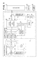
- Fig. 1 is a block diagram showing the arrangement of an image reading apparatus according to the first embodiment of the present invention
- Fig. 2 is a block diagram showing the arrangement of principal part of the image reading apparatus of the first embodiment. The principal arrangement of the image reading apparatus of the first embodiment will be described below with reference to Figs. 1 and 2.
- An image reading apparatus 1 comprises a movable optical unit 4 and electric circuit board 6.
- reference numeral 24 denotes a light source control circuit for turning on a light source 15.
- the circuit 24 comprises a so-called inverter circuit when a cold cathode tube is used as the light source 15.
- Reference numeral 19 denotes an imaging lens which forms an image of light emitted by the light source 15 and reflected by a document on a CCD 20 as a photoelectric conversion element.
- reference numerals 27R, 27G, and 27B denote analog gain adjusters, which can amplify red (R), green (G), and blue (B) analog image signals output from the CCD 20 with variable gains.
- Reference numeral 28 denotes an A/D converter for converting the analog image signals output from the variable analog gain adjusters 27R, 27G, and 27B into digital image signals.
- the CCD 20, analog gain adjusters 27R, 27G, and 27B, and A/D converter 28 construct an image sensor 30 shown in Fig. 2.
- Reference numeral 25 denotes a motor drive circuit for a pulse motor 7, which outputs an excitation switching signal for the pulse motor 7 in response to a signal from a system controller 29.
- Reference numeral 29 denotes a system controller & image processor which executes image processes such as offset correction, shading correction, gamma correction, digital gain adjustment, resolution conversion in the main scan and sub-scan directions, and the like for digital image signals.
- the system controller & image processor 29 serves as a system controller that stores the operation sequence of the entire image reading apparatus 1, and executes various kinds of control in accordance with commands from a host computer 21.
- Reference numeral 22 denotes a communication unit for communicating with the host computer 21.
- the communication unit 22 is implemented by USB.
- other interfaces such as IEEE1394 and the like may be adopted.
- Reference numeral 26 denotes a memory used as a working memory upon executing image processes.
- the memory 26 is used to store shading data for the shading process, gamma curve data for gamma correction, and the like, and is also used as a data buffer upon transferring image data to the host computer 21 via the communication unit 22.
- the memory 26 uses a versatile RAM (random access memory).
- Reference numeral 34 denotes a system bus for connecting the system controller 29 and memory 26.
- the system bus 34 includes address and data buses.
- Reference numeral 35 denotes a power supply which externally supplies electric power to the image reading apparatus 1.
- Fig. 3 is a sectional view showing the internal structure of the image reading apparatus of the first embodiment.
- reference numeral 2 denotes a document pressing cover of the main body of the image reading apparatus 1; and 3, a document to be read. Furthermore, the image reading apparatus 1 comprises the movable optical unit 4, a platen glass 5, the electric circuit board 6, the pulse motor 7, an endless belt 8, pulleys 9 and 10, a gear train 11, a guide rail 12, and a white reference plate 13.
- the optical unit 4 and pulse motor 7 are electrically connected to each other via a cable (not shown).
- the optical unit 4 is slidably placed on the guide rail 12 via mount portions 14.
- the mount portions 14 are fixed to the endless belt 8.
- the optical unit 4 comprises the light source 15, a plurality of reflection mirrors 16, 17, and 18, the imaging lens 19, and the CCD 20.
- the image reading apparatus 1 starts a reading operation in response to a read command from the host computer 21.
- the image reading apparatus 1 turns on the light source 15 in the optical unit 4, makes the plurality of mirrors 16, 17, and 18 reflect light reflected by a document, and forms an image of the reflected light on the CCD 20 via the imaging lens 19, thus reading an image for one line in the main scan direction.
- the drive force of the pulse motor 7 is transmitted to the pulley 9 via the gear train 11 to rotate the pulley 9, thereby driving the endless belt 8.
- the optical unit 4 fixed to the endless belt 8 via the mount portions 14 moves along the guide rail in the sub-scan direction indicated by arrow X.
- the image reading apparatus 1 repeats to read a line image in the main scan direction while moving the optical unit 4 in the sub-scan direction.
- the image reading apparatus 1 moves the optical unit 4 in the sub-scan direction indicated by arrow X up to a position indicated by a dotted line 4 in Fig. 3, thus scanning the entire surface of the platen glass 5.
- a partial image of a document on the platen glass 5 can also be read in accordance with the contents of a read command from the host computer 21.
- the system controller & image processor 29 specifies the range of pixels to be adopted of the outputs from the image sensor 30 in the main scan direction, and the moving range of the optical unit 4 in the sub-scan direction, so as to attain the range of an image to be read designated by the host computer 21.
- the first embodiment further comprises a reset circuit 50 for resetting the system controller 29 when the power supply 35 is turned on, and a power supply line detection circuit 51 as a characteristic feature of the first embodiment.
- the power supply line detection circuit 51 detects a change in potential of a power supply line included in the USB cable 22.
- the detection circuit 51 outputs a reset signal (Reset) to the system controller 29.
- the system controller 29 Upon receiving the reset signal, the system controller 29 is reset since it is set in the same state as that upon receiving a reset signal (Reset) from the reset circuit 50 upon power ON of the power supply 35.
- the system controller 29 controls the light source 15 via the light source control circuit 24, and the pulse motor 7 via the motor drive circuit 25. In this case, since the system controller 29 is reset, their control states are also reset. In the reset state, the light source 15 is turned off, and a current to the pulse motor 7 is stopped.
- step S11 When the power supply 35 of the image reading apparatus 1 is turned on, the system controller 29 is reset in response to the reset signal output from the reset circuit 50 (step S11).
- the power supply line detection circuit 51 checks if a power supply potential V1 of the power supply line included in the USB cable 22 is lower than a predetermined level L1 (step S12). If YES in step S12, step S12 is repeated to monitor the power supply potential V1 while maintaining the reset state. If the power supply potential V1 is equal to or higher than the predetermined level L1, it is determined that the USB cable 22 used to communicate with the host computer 21 is normally connected, and operation is executed in a normal image reading mode (normal mode) (step S13).
- the power supply line detection circuit 51 continuously monitors the power supply potential V1 of the power supply line included in the USB cable 22 (step S14). If the circuit 51 detects that the power supply potential V1 becomes lower than the predetermined level L1 (YES in step S14), it determines that a communication with the host computer 21 is abnormal or is disconnected, the circuit 51 issues a reset signal (Reset) to the system controller 29 (step S15).
- the system controller 29 Upon receiving the reset signal, the system controller 29 is reset (step S16). Since the system controller 29 is reset, control of the light source 15 via the light source control circuit 24, and that of the pulse motor 7 via the motor drive circuit 25 by the system controller 29 are also reset. In this reset state, since the light source 15 is turned off, and a current to be supplied to the pulse motor 7 is stopped, a power saving mode is set. That is, in the first embodiment, currents consumed by the light source 15 and pulse motor 7 assume minimum values.
- the system controller 29 is reset before the apparatus operation becomes unstable, and currents consumed by the light source 15 and pulse motor 7 instantaneously become minimum values.
- the system controller 29 is reset, since supply of clock signals and access to the memory 26 stop, consumption power in the apparatus can be minimized.
- the light source 15 is turned off.
- the energization amount may be lowered.
- Fig. 4 is a block diagram showing the arrangement of principal part of an image reading apparatus according to the second embodiment of the present invention.
- the same reference numerals in Fig. 4 denote the same parts as in Fig. 2, and a description thereof will be omitted.
- the arrangement of the second embodiment comprises a data line detection circuit 61 in place of the power supply line detection circuit 51 in the arrangement of the first embodiment shown in Figs. 1 and 2.
- the data line detection circuit 61 detects a change in potential on a data line in the USB cable 22, and outputs a sleep signal (Sleep) to the light source control circuit 24 and pulse motor drive circuit 25 when the data line is disconnected upon unplugging the USB cable 22 or any abnormality is found.
- a sleep signal Sleep
- the light source control circuit 24 and pulse motor drive circuit 25 respectively control the light source 15 and pulse motor 7 under the control of the system controller 29.
- the sleep signal issued by the data line detection circuit 61 has higher priority than control signals normally received from the system controller 29. In a sleep state in which the sleep signal is issued, the light source 15 is turned off, and currents to be supplied to the pulse motor 7 are stopped.
- the operation starts in the normal image reading mode (normal mode) in step S21.
- the data line detection circuit 61 checks if a potential V2 of the data line included in the USB cable 22 is lower than a predetermined level L2 (step S22). If the potential V2 of the data line is equal to or higher than the predetermined level L2, since it is determined that the USB cable 22 used to communicate with the host computer 21 is normally connected, the flow returns to step S22 to proceed with operation in the normal mode without issuing a sleep signal, thus monitoring the power supply and the potential V2 on the data line.
- the data line detection circuit 61 determines that a communication with the host computer 21 is disconnected, and issues a sleep signal (Sleep) to the light source control circuit 24 and pulse motor drive circuit 25 (step S23).
- the light source control circuit 24 and pulse motor drive circuit 25 Upon receiving the sleep signal, the light source control circuit 24 and pulse motor drive circuit 25 set their operations in a sleep state since the sleep signal has priority over normal control signals received from the system controller 29. In this sleep state, predetermined circuits are set in a power saving mode. That is, in the second embodiment, the light source 15 is turned off, and currents to be supplied to the pulse motor 7 are stopped.
- the light source 15 is turned off.
- the energization amount may be lowered.
- the image reading apparatus does not comprise any CPU.
- the present invention may be applied to an apparatus that comprises a CPU.
- an image reading apparatus that comprises a CPU in a system controller will be explained below.
- Fig. 5 is a block diagram showing the arrangement of principal part of an image reading apparatus according to the third embodiment of the present invention.
- the same reference numerals in Fig. 5 denote the same parts as in Fig. 2, and a description thereof will be omitted.
- the arrangement of the third embodiment comprises a CPU and the like in a system controller in the arrangement of the first embodiment shown in Figs. 1 and 2. That is, a system controller 29A of the third embodiment comprises an image processing circuit 29-1, CPU 29-2, ROM 29-3, and RAM 29-4. Furthermore, the power supply line detection circuit 51 detects whether or not a power supply voltage of the USB cable 22 is normally supplied from the host computer 21, and outputs an ON detection signal VbusON to the system controller 29A if the power supply voltage is normally supplied. Note that the detection signal VbusON is output to the system controller 29A via a route different from that of a reset signal output from the reset circuit 50.
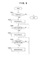
- Fig. 6 is a flow chart showing an outline of the normal scan operation in the third embodiment
- Fig.7 is a flow chart showing the timer interrupt operation as a characteristic feature of the third embodiment.
- step S201 if the power supply 35 of the apparatus is turned on (step S201), the CPU 29-2 is reset in response to an output (Reset signal) from the reset circuit 50.
- Initial values are set in various flags and memory in the system controller 29A (step S202), and the control waits for an instruction from the host computer 21 (step S203). If the host computer 21 confirms connection with the image reading apparatus 1, it issues a reset instruction to the image reading apparatus 1.
- the image reading apparatus 1 adjusts the light source 15 to turn it on, and executes initialization such as setup of the home position of the pulse motor 7, acquisition of shading correction data, permission of timer interrupt, and the like in accordance the initialization instruction (step S204).
- control waits for an image read scan instruction from the host computer 21 (step S205).
- image read scan instruction Upon receiving the image read scan instruction, clock signals CLK are supplied to the image sensor 30, and the pulse motor 7 is driven to scan a document image, thereby reading an image within the read range designated by the host computer 21.
- the read image data is then output to the host computer 21 (step S206).
- step S210 Upon generation of a timer interrupt (step S210), it is checked if the input VbusON from the power supply line detection circuit 51 is ON (step S211). Since the power supply voltage of USB cannot be detected when the USB cable 22 is not connected to the host computer 21 or when any abnormality is detected upon inadvertently unplugging a connector to disrupt a communication in progress, the signal VbusON is OFF.
- the CPU If the signal VbusON is OFF, the CPU is set in a sleep state even during an image reading process, and supply of clock signals CLK to the image sensor 30 is stopped. Also, an emission stop signal is supplied to the light source control circuit 24 to turn off the light source 15, and a stop signal is output to the pulse motor drive circuit 25 to stop the pulse motor 7 even during driving (step S212).
- the power saving mode is set for some respective circuits, e.g., a clock IC, the light source lamp, motor, and the like, but some circuits need not always be completely turned off and their consumption power need only be reduced in the power saving mode (the same applies to other embodiments).
- step S213 If it is detected that the signal VbusON is ON, the interrupt process normally ends (step S213).
- the program size can be reduced, and power savings in the image reading apparatus can be achieved.
- the pulse motor 7 is controlled to be merely immediately stopped.
- the pulse motor 7 may be stopped after it is controlled to be returned to its home position, i.e., to reset its mechanical position.
- the present invention is not limited to the apparatuses of the aforementioned embodiments, and includes not only an apparatus which executes initialization immediately after any abnormality of a communication path is detected, but also an apparatus which executes initialization after it normally recovers the communication path.
- the object of the present invention can also be achieved by providing a storage medium storing program codes for performing the aforesaid processes to a computer system or apparatus (e.g., a personal computer), reading the program codes, by a CPU or MPU of the computer system or apparatus, from the storage medium, then executing the program.
- a computer system or apparatus e.g., a personal computer
- the program codes read from the storage medium realize the functions according to the third embodiment, and the storage medium storing the program codes constitutes the invention.
- the storage medium such as a floppy disk, a hard disk, an optical disk, a magneto-optical disk, CD-ROM, CD-R, a magnetic tape, a non-volatile type memory card, and ROM can be used for providing the program codes.
- the present invention includes a case where an OS (operating system) or the like working on the computer performs a part or entire processes in accordance with designations of the program codes and realizes functions according to the above third embodiment.
- the present invention also includes a case where, after the program codes read from the storage medium are written in a function expansion card which is inserted into the computer or in a memory provided in a function expansion unit which is connected to the computer, CPU or the like contained in the function expansion card or unit performs a part or entire process in accordance with designations of the program codes and realizes functions of the above embodiments.
- the storage medium stores program codes corresponding to the flowchart in Fig. 7 described in the third embodiment.
- an image reading apparatus which has an image sensing unit for reading an image, and a communication unit for transferring an image signal read by the image sensing unit to an external apparatus, a detector detects the presence/absence of abnormality of the communication unit, and when the detector detects any abnormality of the communication unit, the image reading apparatus is set in a power saving mode.
Landscapes
- Engineering & Computer Science (AREA)
- Multimedia (AREA)
- Signal Processing (AREA)
- General Engineering & Computer Science (AREA)
- Computing Systems (AREA)
- Facsimiles In General (AREA)
- Facsimile Scanning Arrangements (AREA)
- Image Input (AREA)
Abstract
Description
Claims (28)
- An image reading apparatus which comprises an image sensing unit for reading an image, and a communication unit for transferring an image signal read by the image sensing unit to an external apparatus, comprising:a detector for detecting presence/absence of abnormality of the communication unit; anda controller for, when said detector detects any abnormality of the communication unit, setting said image reading apparatus in a power saving mode.
- The apparatus according to claim 1, wherein at least one of an internal circuit and mechanical position of the image sensing unit is initialized in the power saving mode.
- The apparatus according to claim 1, wherein at least one of an internal circuit and function of the image sensing unit is set in a sleep state in the power saving mode.
- The apparatus according to claim 1, wherein the image sensing unit comprises:a light source for irradiating a document with light;an image sensor for converting light reflected by a document irradiated with light from said light source into an electrical image signal;a moving unit for moving a relative position between an image of the document and said image sensor; anda setting unit for setting at least one of said light source and said moving unit in the power saving mode in accordance with a setup of said controller.
- The apparatus according to claim 1, further comprising an A/D converter for converting the image signal output from the image sensing unit into a digital signal,
wherein the communication unit transfers the digital image signal converted by said A/D converter to the external apparatus. - The apparatus according to claim 1, wherein said detector detects any abnormality of the communication unit by detecting a change in potential of a power supply line included in the communication unit.
- The apparatus according to claim 1, wherein said detector detects any abnormality of the communication unit by detecting a change in potential of a data line included in the communication unit.
- The apparatus according to claim 1, wherein the communication unit has a function of allowing to plug/unplug a cable without turning off a power supply of the external apparatus.
- The apparatus according to claim 8, wherein the function of the communication unit complies with USB or IEEE1394.
- A control method for an image reading apparatus which comprises an image sensing unit for reading an image, and a communication unit for transferring an image signal read by the image sensing unit to an external apparatus, comprising:a detection step of detecting presence/absence of abnormality of the communication unit; anda control step of setting, when any abnormality of the communication unit is detected in the detection step, the image reading apparatus in a power saving mode.
- The method according to claim 10, wherein at least one of an internal circuit and mechanical position of the image sensing unit is initialized in the power saving mode.
- The method according to claim 10, wherein at least one of an internal circuit and function of the image sensing unit is set in a sleep state in the power saving mode.
- The method according to claim 10, further comprising:an A/D conversion step of converting the image signal output from the image sensing unit into a digital signal; anda transfer step of transferring the digital image signal converted in the A/D conversion step from the communication unit to the external apparatus.
- The method according to claim 10, wherein the detection step includes a step of detecting any abnormality of the communication unit by detecting a change in potential of a power supply line included in the communication unit.
- The method according to claim 10, wherein the detection step includes a step of detecting any abnormality of the communication unit by detecting a change in potential of a data line included in the communication unit.
- The method according to claim 10, wherein the communication unit has a function of allowing to plug/unplug a cable without turning off a power supply of the external apparatus.
- The method according to claim 16, wherein the function of the communication unit complies with USB or IEEE1394.
- An image processing system which comprises an image reading apparatus for outputting an image signal read by an image sensing unit to a communication unit, and a host apparatus for processing the image signal sent from the image reading apparatus via the communication unit,
the image reading apparatus comprising:a detector for detecting presence/absence of abnormality of the communication unit; anda controller for, when said detector detects any abnormality of the communication unit, setting the image reading apparatus in a power saving mode. - The system according to claim 18, wherein at least one of an internal circuit and mechanical position of the image sensing unit is initialized in the power saving mode.
- The system according to claim 18, wherein at least one of an internal circuit and function of the image sensing unit is set in a sleep state in the power saving mode.
- The system according to claim 18, further comprising an A/D converter for converting the image signal output from the image sensing unit into a digital signal,
wherein the communication unit transfers the digital image signal converted by said A/D converter to the host apparatus. - The system according to claim 18, wherein said detector detects any abnormality of the communication unit by detecting a change in potential of a power supply line included in the communication unit.
- The system according to claim 18, wherein said detector detects any abnormality of the communication unit by detecting a change in potential of a data line included in the communication unit.
- The system according to claim 18, wherein the communication unit has a function of allowing to plug/unplug a cable without turning off a power supply of the host apparatus.
- The system according to claim 24, wherein the function of the communication unit complies with USB or IEEE1394.
- A storage medium that stores a program for implementing a control method for an image reading apparatus which comprises an image sensing unit for reading an image, a communication unit for transferring an image signal read by the image sensing unit to an external apparatus, and a detector for detecting presence/absence of abnormality of the communication unit, comprising:computer readable program code means for, when the detector detects any abnormality of the communication unit, setting the image reading apparatus in a power saving mode.
- The medium according to claim 26, wherein the communication unit has a function of allowing to plug/unplug a cable without turning off a power supply of the external apparatus.
- The medium according to claim 27, wherein the function of the communication unit complies with USB or IEEE1394.
Applications Claiming Priority (2)
| Application Number | Priority Date | Filing Date | Title |
|---|---|---|---|
| JP2000234553A JP2002051195A (en) | 2000-08-02 | 2000-08-02 | Image reading apparatus, control method thereof, image processing system, and storage medium |
| JP2000234553 | 2000-08-02 |
Publications (2)
| Publication Number | Publication Date |
|---|---|
| EP1178667A2 true EP1178667A2 (en) | 2002-02-06 |
| EP1178667A3 EP1178667A3 (en) | 2004-05-19 |
Family
ID=18726903
Family Applications (1)
| Application Number | Title | Priority Date | Filing Date |
|---|---|---|---|
| EP01118526A Withdrawn EP1178667A3 (en) | 2000-08-02 | 2001-08-01 | Image reading apparatus and its control method |
Country Status (5)
| Country | Link |
|---|---|
| US (1) | US20020015174A1 (en) |
| EP (1) | EP1178667A3 (en) |
| JP (1) | JP2002051195A (en) |
| CN (1) | CN1336617A (en) |
| TW (1) | TW529288B (en) |
Cited By (1)
| Publication number | Priority date | Publication date | Assignee | Title |
|---|---|---|---|---|
| WO2007013512A1 (en) | 2005-07-28 | 2007-02-01 | Ricoh Company, Ltd. | Image processor and its control method |
Families Citing this family (8)
| Publication number | Priority date | Publication date | Assignee | Title |
|---|---|---|---|---|
| US10453151B2 (en) | 2001-02-01 | 2019-10-22 | Kris Engineering, Inc. | Receipts scanner and financial organizer |
| US7746510B2 (en) | 2001-02-01 | 2010-06-29 | Pandipati Radha K C | Receipts scanner and financial organizer |
| KR20040016289A (en) * | 2002-08-16 | 2004-02-21 | (주)하이비젼시스템 | Image process tool kit and control method made up Universal Serial Bus interface |
| US8018607B2 (en) * | 2002-12-05 | 2011-09-13 | Hewlett-Packard Development Company, L.P. | Scanner power management system and method |
| US20050289257A1 (en) * | 2004-06-24 | 2005-12-29 | Fink Thomas M | Self-powered USB device with USB power line reset and related USB host and USB system |
| US20060224908A1 (en) * | 2005-04-04 | 2006-10-05 | Kyocera Mita Corporation | Sharing apparatus and energy conservation controlling method therefor |
| TWM367535U (en) * | 2009-05-19 | 2009-10-21 | Genesys Logic Inc | Dual power device and scanning apparatus employing the same |
| JP5743391B2 (en) * | 2009-09-24 | 2015-07-01 | キヤノン株式会社 | Control device and image forming apparatus |
Family Cites Families (15)
| Publication number | Priority date | Publication date | Assignee | Title |
|---|---|---|---|---|
| US4569585A (en) * | 1982-06-17 | 1986-02-11 | Canon Kabushiki Kaisha | Image forming apparatus |
| US5065189A (en) * | 1989-11-27 | 1991-11-12 | Mita Industrial Co., Ltd. | Electrophotographic copying machine and method of setting copy magnification |
| CA2062106C (en) * | 1991-12-23 | 2002-08-20 | Gregg Marwin | Object sensing system for bar code laser scanners |
| JP3325362B2 (en) * | 1993-01-18 | 2002-09-17 | 株式会社リコー | Facsimile machine |
| US5758040A (en) * | 1995-01-26 | 1998-05-26 | Ricoh Company, Ltd. | Energy-saving facsimile apparatus and energy-saving method for facsimile apparatus |
| US5720560A (en) * | 1995-02-22 | 1998-02-24 | Star Micronics Co., Ltd. | Printing apparatus |
| JPH08328516A (en) * | 1995-06-02 | 1996-12-13 | Canon Inc | Display device and method |
| JP3093622B2 (en) * | 1995-11-29 | 2000-10-03 | 株式会社東芝 | Image forming device |
| JP3889135B2 (en) * | 1996-11-28 | 2007-03-07 | 株式会社東芝 | Image forming apparatus and image forming method |
| JP3482795B2 (en) * | 1996-12-17 | 2004-01-06 | ミノルタ株式会社 | Image reading device |
| JPH10243327A (en) * | 1997-02-28 | 1998-09-11 | Canon Inc | Image input device, control method thereof, and image input / output system |
| US5956158A (en) * | 1997-04-01 | 1999-09-21 | Storm Technology, Inc. | Scanner powered by peripheral bus |
| JP3264215B2 (en) * | 1997-06-05 | 2002-03-11 | 富士ゼロックス株式会社 | IMAGE FORMING APPARATUS, INITIALIZATION METHOD THEREOF, AND MEDIUM RECORDING INITIALIZATION PROGRAM FOR IMAGE FORMING APPARATUS |
| US6039428A (en) * | 1998-05-13 | 2000-03-21 | Hewlett-Packard Company | Method for improving ink jet printer reliability in the presence of ink shorts |
| JP3293779B2 (en) * | 1998-08-25 | 2002-06-17 | キヤノン株式会社 | Signal processing device and control method thereof |
-
2000
- 2000-08-02 JP JP2000234553A patent/JP2002051195A/en active Pending
-
2001
- 2001-08-01 TW TW090118776A patent/TW529288B/en active
- 2001-08-01 EP EP01118526A patent/EP1178667A3/en not_active Withdrawn
- 2001-08-01 US US09/919,706 patent/US20020015174A1/en not_active Abandoned
- 2001-08-02 CN CN01124547.6A patent/CN1336617A/en active Pending
Cited By (3)
| Publication number | Priority date | Publication date | Assignee | Title |
|---|---|---|---|---|
| WO2007013512A1 (en) | 2005-07-28 | 2007-02-01 | Ricoh Company, Ltd. | Image processor and its control method |
| EP1909474A4 (en) * | 2005-07-28 | 2008-07-30 | Ricoh Kk | Image processor and its control method |
| US7765413B2 (en) | 2005-07-28 | 2010-07-27 | Ricoh Company, Ltd. | Image processing device and method of controlling the image processing device which estimates a state-transition sequence for a USB driver |
Also Published As
| Publication number | Publication date |
|---|---|
| TW529288B (en) | 2003-04-21 |
| CN1336617A (en) | 2002-02-20 |
| JP2002051195A (en) | 2002-02-15 |
| EP1178667A3 (en) | 2004-05-19 |
| US20020015174A1 (en) | 2002-02-07 |
Similar Documents
| Publication | Publication Date | Title |
|---|---|---|
| US6963429B2 (en) | Image sensing apparatus and control method therefor | |
| JP4444710B2 (en) | Image processing apparatus, control method therefor, program, and storage medium | |
| EP1178667A2 (en) | Image reading apparatus and its control method | |
| US6995877B2 (en) | Image reading apparatus and its control method | |
| US20200045188A1 (en) | Power receiving apparatus, control method thereof and storage medium | |
| US7187479B2 (en) | Image reading apparatus | |
| JP3705134B2 (en) | Image reading device | |
| US8314977B2 (en) | Image reading device and image forming apparatus | |
| US5748340A (en) | Image reading apparatus capable of rapid transition from a standby mode to a stable operational mode | |
| JP2000113163A (en) | Image reading device, image reading method, and storage medium | |
| US5914789A (en) | Facsimile apparatus with printer function for connecting to an external computer | |
| US20090230773A1 (en) | Scanner with battery | |
| US20050206761A1 (en) | Photoelectric conversion apparatus and image reading apparatus | |
| JPH06189132A (en) | Image reader | |
| US5923373A (en) | Communication system for communicating between two microcomputers | |
| KR100288712B1 (en) | Apparatus for automatic gain control and method for lamp control use of it in scanner | |
| JP2000069285A (en) | Image reading device | |
| JPH048199A (en) | Image reader | |
| JP3991580B2 (en) | SCSI peripherals | |
| JP3969191B2 (en) | Peripheral device | |
| JPH1146302A (en) | Image reading device | |
| JPH0662292A (en) | Video camera | |
| JP2002033889A (en) | Image reading apparatus and control method thereof | |
| JPH10210219A (en) | Color picture processor | |
| JP2001027915A (en) | I / O device |
Legal Events
| Date | Code | Title | Description |
|---|---|---|---|
| PUAI | Public reference made under article 153(3) epc to a published international application that has entered the european phase |
Free format text: ORIGINAL CODE: 0009012 |
|
| AK | Designated contracting states |
Kind code of ref document: A2 Designated state(s): AT BE CH CY DE DK ES FI FR GB GR IE IT LI LU MC NL PT SE TR |
|
| AX | Request for extension of the european patent |
Free format text: AL;LT;LV;MK;RO;SI |
|
| PUAL | Search report despatched |
Free format text: ORIGINAL CODE: 0009013 |
|
| AK | Designated contracting states |
Kind code of ref document: A3 Designated state(s): AT BE CH CY DE DK ES FI FR GB GR IE IT LI LU MC NL PT SE TR |
|
| AX | Request for extension of the european patent |
Extension state: AL LT LV MK RO SI |
|
| 17P | Request for examination filed |
Effective date: 20041001 |
|
| 17Q | First examination report despatched |
Effective date: 20041125 |
|
| AKX | Designation fees paid |
Designated state(s): DE FR GB |
|
| STAA | Information on the status of an ep patent application or granted ep patent |
Free format text: STATUS: THE APPLICATION HAS BEEN WITHDRAWN |
|
| 18W | Application withdrawn |
Effective date: 20090212 |