EP1178617B1 - Method for improving the performance of the GSM frequency hopping sequence generator for half/quarter rate channels - Google Patents
Method for improving the performance of the GSM frequency hopping sequence generator for half/quarter rate channels Download PDFInfo
- Publication number
- EP1178617B1 EP1178617B1 EP01301193A EP01301193A EP1178617B1 EP 1178617 B1 EP1178617 B1 EP 1178617B1 EP 01301193 A EP01301193 A EP 01301193A EP 01301193 A EP01301193 A EP 01301193A EP 1178617 B1 EP1178617 B1 EP 1178617B1
- Authority
- EP
- European Patent Office
- Prior art keywords
- frame
- time slot
- carrier frequencies
- channel
- assigning
- Prior art date
- Legal status (The legal status is an assumption and is not a legal conclusion. Google has not performed a legal analysis and makes no representation as to the accuracy of the status listed.)
- Expired - Lifetime
Links
- 238000000034 method Methods 0.000 title claims description 19
- 238000004891 communication Methods 0.000 claims description 23
- 238000005562 fading Methods 0.000 description 9
- 230000005540 biological transmission Effects 0.000 description 8
- 230000015556 catabolic process Effects 0.000 description 4
- 238000006731 degradation reaction Methods 0.000 description 4
- 238000012546 transfer Methods 0.000 description 4
- 125000004122 cyclic group Chemical group 0.000 description 3
- 238000010586 diagram Methods 0.000 description 3
- 230000000694 effects Effects 0.000 description 3
- 230000001010 compromised effect Effects 0.000 description 2
- 230000003044 adaptive effect Effects 0.000 description 1
- 239000002131 composite material Substances 0.000 description 1
- 230000007423 decrease Effects 0.000 description 1
- 230000003247 decreasing effect Effects 0.000 description 1
- 230000003111 delayed effect Effects 0.000 description 1
- 230000001419 dependent effect Effects 0.000 description 1
- 230000003467 diminishing effect Effects 0.000 description 1
- 239000006185 dispersion Substances 0.000 description 1
- 238000005516 engineering process Methods 0.000 description 1
- 238000011156 evaluation Methods 0.000 description 1
- 238000010295 mobile communication Methods 0.000 description 1
- 238000012986 modification Methods 0.000 description 1
- 230000004048 modification Effects 0.000 description 1
- 230000008707 rearrangement Effects 0.000 description 1
- 230000003252 repetitive effect Effects 0.000 description 1
- 238000006467 substitution reaction Methods 0.000 description 1
Images
Classifications
-
- H—ELECTRICITY
- H04—ELECTRIC COMMUNICATION TECHNIQUE
- H04J—MULTIPLEX COMMUNICATION
- H04J13/00—Code division multiplex systems
-
- H—ELECTRICITY
- H04—ELECTRIC COMMUNICATION TECHNIQUE
- H04B—TRANSMISSION
- H04B1/00—Details of transmission systems, not covered by a single one of groups H04B3/00 - H04B13/00; Details of transmission systems not characterised by the medium used for transmission
- H04B1/69—Spread spectrum techniques
- H04B1/713—Spread spectrum techniques using frequency hopping
- H04B1/7143—Arrangements for generation of hop patterns
-
- H—ELECTRICITY
- H04—ELECTRIC COMMUNICATION TECHNIQUE
- H04B—TRANSMISSION
- H04B7/00—Radio transmission systems, i.e. using radiation field
- H04B7/24—Radio transmission systems, i.e. using radiation field for communication between two or more posts
- H04B7/26—Radio transmission systems, i.e. using radiation field for communication between two or more posts at least one of which is mobile
- H04B7/2643—Radio transmission systems, i.e. using radiation field for communication between two or more posts at least one of which is mobile using time-division multiple access [TDMA]
- H04B7/265—Radio transmission systems, i.e. using radiation field for communication between two or more posts at least one of which is mobile using time-division multiple access [TDMA] for channel frequency control
Definitions
- This invention relates to methods of assigning a carrier frequency to a communication channel of a plurality of communication channels defined by time slots within sequentially occurring frames.
- a common transmission problem in mobile telephone systems is that of fading. This occurs as a result of the shadowing effect produced by buildings and natural obstacles such as hills located between the transmitting and receiving antennas of a mobile terminal and a base station. As the mobile terminal moves around, the received signal strength increases and decreases as a function of the type of obstacles which are that moment between the transmitting and receiving antennas.
- Another type of signal degradation occurs when the broadcast signal takes more than one path from the transmitting antenna to the receiving antenna so that the receiving antenna of the mobile terminal receives not just one signal but several.
- One of these multiple signals may come directly from the receiving antenna while several others may be first reflected from buildings and other obstructions before reaching the receiving antenna and, thus, will be delayed slightly in phase from one another.
- the reception of several versions of the same signal shifted in phase from one another results in the vector sum of the signals being the resultant composite signal actually received at the receiving antenna. In some instances the vector sum of the received signal may be very low or even close to zero which can cause the received signal to virtually disappear.
- time dispersion can occur when a signal representing certain digital information is interfered with at the receiving antenna by a different, consecutively transmitted symbol due to reflections of the original signal from an object distant from the receiving antenna. In this instance the receiver has difficulty in accurately identifying the actual symbol that is being detected at that moment.
- TDMA Time Division Multiple Access
- Frequency hopping means that a mobile terminal sequentially communicates with a base station on different frequencies, the transmission frequency of both the mobile terminal and the base station changing between frames of information.
- a mobile terminal will generally use the same time slot of a frame, but will tune to a different frequency between each frame under the GSM standard.
- the base station receivers will also retune to the next frequency to match the frequency hop of the mobile terminal to maintain the communication link. It is to be noted that communications from the base station to the mobile terminal (the downlink) and communications from the mobile terminal to the base station (the uplink) are at different frequencies in GSM.
- the radio transmission and reception are at one carrier frequency for one instant of time and then, a very short time later, the transmission and reception is hopped to a different frequency.
- a transmitted radio signal is at a different carrier frequency, it is not subject to the same fading pattern because such patterns are normally frequency dependent and, therefor, different for different frequencies.
- a stationary mobile terminal which may have very poor reception of one carrier frequency and have very good reception at a different carrier frequency.
- frequency hopping is used to further limit the amount of signal loss to a relatively short segment of the actual transmission time span.
- frequency hopping One important aspect of frequency hopping is that the two or more carrier frequencies between which the signal is successively hopped must each be separated by a certain minimum amount in order to experience independent fading of the different frequencies.
- the frequencies between which the signals are hopped must be sufficiently different from one another so that if the received signal is weak for one frequency it should not be weak for the other frequency. If the two frequencies are very close together, it is more likely that the received signal will be weak due to fading of both frequencies. If, however, the two frequencies are separated from one another by a sufficiently large value, then it is less likely that each of the received signals will be weak at the same time.
- the traffic channels are intended to carry two types of user information streams: encoded speech and data. Two of the four types of traffic channels are defined as full rate and half rate.
- the access scheme is Time Division Multiple Access (TDMA) with eight basic physical channels per carrier. A physical channel is therefore defined as a sequence of TDMA frames, a time slot number (modulo 8) and a frequency hopping sequence for a given number of frequencies.
- TDMA Time Division Multiple Access
- the main advantage of frequency hopping is to provide diversity on one transmission link and also to average the quality on all the communications through interferers diversity. Every mobile transmits its time slots according to a sequence of frequencies that it derives from an algorithm.
- the frequency hopping occurs between frames and, therefore, a mobile station transmits, or receives, on a fixed frequency during one time slot and then must hop before the time slot on the next TDMA frame.
- the frequency hopping sequences are orthogonal inside one cell, i.e., no collisions occur between communications of the same call; and, independent from one cell to a homologue cell, i.e., using the same set of RF channels or cell allocations.
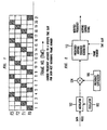
- FIG. 1 is a graphical illustration of a GSM full rate channel where the frequency hopping sequence uses four discrete carrier frequencies, F0, F1, F2 and F3, to transmit mobile call information on a common time slot for each next occurring frame.
- time slot 1 of frame 2 is not used and, therefore, carrier frequency F1 is bypassed.
- the next time slot used to carry the call information is in frame 5 which uses carrier frequeacy F0.
- the call information is spread over four separate and discrete carrier frequencies to help reduce the effects of fading and/or signal degradation.
- the call information is carried on only two of the available four carrier frequencies. Two of the four available carrier frequencies are not used.
- the call information is transmitted on only one of the four available carrier frequencies. Three of the four available carrier frequencies are not used.
- half rate and quarter rate channels are not as effective as a full rate channel in reducing the effects of fading and/or signal degradation because all of the available carrier frequencies are not used.
- WO 96/36132 discloses a method and system for multirate coding and detecting in a multiple access mobile communication.
- a transmitter selects a data transfer rate, and codes the transfer rate information to a transmitted signal by using a signal waveform, which is allocated to the transfer rate.
- the signal waveform of the received signal is detected, and the transfer rate in the reception is selected according to the detected signal waveform.
- the present invention solves the aforementioned problem of decreased signal performance which occurs during half rate and lower channel rate relative to a full channel rate by assigning one of a plurality of discrete carrier frequencies to a time slot of each occurring frame assigned to a specific information channel until each of the plurality of discrete carrier frequencies has been assigned at which time the cycle of assigning carrier frequencies to time slots is repeated.
- a carrier frequency is assigned to a communication channel in a communication system having communication channels defined by time slots within sequentially occurring frames.
- a position of a frame having a time slot assigned to the communication channel is determined and a carrier frequency belonging to a plurality of carrier frequencies is assigned to the time slot using one of a plurality of associations between frame positions and the plurality of carrier frequencies.
- One of the plurality of associations is selected for use in assigning the carrier frequency based on a communication rate used by the communication channel.
- a first association between frame positions and the plurality of carrier frequencies is used to assign a carrier frequency to a time slot when communicating at a first communication rate
- a second association between frame positions and the plurality of carrier frequencies is used to assign a carrier frequency to a time slot when communicating at a second communication rate
- the same carrier frequency may be assigned to more than one time slot in a frame.
- the digitally encoded voice channels are designed for authorizing either "full rate” or "half rate” channel.
- Data transmission may also be provided for "full rate” and "half rate” channel.
- full rate channel the same time slot of every frame is assigned to a specific information channel.
- half rate channel the same time slot of every other frame is assigned to a specific information channel.
- quarter rate channel the same time slot of every fourth frame is assigned to a specific information channel.
- the current GSM frequency hopping sequence generator is designed for full rate channel.
- the performance of the current system declines when less than full rate channel is used because the total number of carrier frequency signals available for use to transmit the voice or data information are not used.
- half rate channel only two (F0 and F2) of the available four (F0, F1, F2, F3) carrier frequency signals are used.
- F2 carrier frequency
- F1, F2, F3 carrier frequency
- EDGE Enhanced Data GSM Evaluation Access Network
- AMR Adaptive Multi Rate
- intelligent antenna half rate channel will be used more frequently because capacity enhancement will become more important.
- the invention here disclosed enables, for the first time, a GSM system using less than full rate channel to achieve the same level of performance quality as is obtained for full rate channel provided the number of discrete carrier frequency signals available for use and the reciprocal of the channel code hopping rate have a common divisor.
- the common divisor is 2.
- the common divisor is also 2.
- the GSM frequency hopping sequence generator as defined in GSM 05-02, generates carrier frequencies using the system common frame number to increment every frame for a full rate channel.
- the same level of performance quality obtained for full rate channel can also be obtained for half rate and lower channel. This is obtained by dividing the position number of the upcoming frame (the frame number) by two, rounding the result down to the nearest integer if the result is not an integer and using the obtained integer as the new frame number to trigger the GSM frequency hopping sequence generator.
- f 1 / n f n / 2
- f n the position number of the upcoming frame having a . time slot assigned to the information channel
- f 1 / n is the position number of the frame that is to be used as the trigger signal for the sequence generator to generate the actual carrier frequency that is to be used for the upcoming time slot of frame f n
- "2" is the divisor used for half (1/2) rate channel.
- the carrier frequencies used to transmit call information for a specific information channel are F0, F2, F0, F2, F0, F2, F0, F2, F0 ..., respectively.
- the prior art system uses only two of the available four carrier frequencies.
- the carrier frequencies that will be used are F0, F0, F1, F2, F3, F0, F1, F2, F3 ....
- the carrier frequencies are F0, F0, F1, F2, F3, F0, F1, F2, F3 ....
- at half rate channel neither two, nor three, but all four of the carrier frequencies will be used.
- FIG. 2 there is illustrated a block diagram of structure for generating a frequency hopping carrier frequency modulated by voice or data information.
- a signal from oscillator 100 is modulated by a voice or data signal in modulator 102, the output of which is directed to an input terminal of multiplier 104.
- a second input terminal of multiplier 104 is coupled to receive a signal from frequency synthesizer 106.
- the output of multiplier 104 is coupled to an input of frequency hopping sequence generator 112.
- Two signals, a frame number signal and a time slot position signal are also directed to the frequency hopping sequence generator 112.
- the frequency hopping sequence generator tracks the time slot position, the frame number and the frequency hopping rate to generate the appropriate carrier frequency for each time slot of each frame number.
- each user is assigned a fixed time slot in every other frame.
- a specific user will be assigned a fixed time slot in frame numbers 1, 3, 5, 7, 9, 11, 13 ....
- the output signal of the frequency hopping sequence generator will increment carrier frequencies, for that time slot, of F0, F1, F2, F3, F0, F1, F2 ... for frame numbers 1, 3, 5, 7, 9, 11 13 ....
- the frequency hopping sequence generator 112 will generate carrier frequencies of F0, F1, F2, F3, F0, F1, F2... for the assigned time slot of frame numbers 1, 5, 9, 13, 17 ....
- the association between frame positions and carrier frequencies is (1, F0); (5, F1); (9, F2); (13, F3); (17, F0), (21, F1); ....
- the position of a frame having a time slot assigned to a communication channel is determined, and then a carrier frequency is assigned to the time slot using a first association between frame position and carrier frequencies when operating at one channel rate, and when operating at a different channel rate, a carrier frequency is assigned to the time slot using a different association between frame position and carrier frequencies.
- the selection of the appropriate carrier frequencies can be obtained from look up tables or from a processor programmed to associate frame positions with carrier frequencies based on a channel rate.
- the invention here disclosed references systems such as a GSM system operating with cyclic hopping where the hopping pattern is repeated. It is to be noted that GSM has one cyclic hopping sequence, as referenced above, and 63 random hopping sequences. A random hopping sequence does not have a repetitive pattern. This invention is not restricted to the cyclic hopping sequence of GSM but also provides improved results for all random hopping sequences.
Landscapes
- Engineering & Computer Science (AREA)
- Computer Networks & Wireless Communication (AREA)
- Signal Processing (AREA)
- Mobile Radio Communication Systems (AREA)
- Time-Division Multiplex Systems (AREA)
Description
- This invention relates to methods of assigning a carrier frequency to a communication channel of a plurality of communication channels defined by time slots within sequentially occurring frames.
- A common transmission problem in mobile telephone systems is that of fading. This occurs as a result of the shadowing effect produced by buildings and natural obstacles such as hills located between the transmitting and receiving antennas of a mobile terminal and a base station. As the mobile terminal moves around, the received signal strength increases and decreases as a function of the type of obstacles which are that moment between the transmitting and receiving antennas.
- Another type of signal degradation occurs when the broadcast signal takes more than one path from the transmitting antenna to the receiving antenna so that the receiving antenna of the mobile terminal receives not just one signal but several. One of these multiple signals may come directly from the receiving antenna while several others may be first reflected from buildings and other obstructions before reaching the receiving antenna and, thus, will be delayed slightly in phase from one another. The reception of several versions of the same signal shifted in phase from one another results in the vector sum of the signals being the resultant composite signal actually received at the receiving antenna. In some instances the vector sum of the received signal may be very low or even close to zero which can cause the received signal to virtually disappear.
- In the case of digital radio systems such as those in which Time Division Multiple Access (TDMA) is used, a problem referred to as time dispersion can occur when a signal representing certain digital information is interfered with at the receiving antenna by a different, consecutively transmitted symbol due to reflections of the original signal from an object distant from the receiving antenna. In this instance the receiver has difficulty in accurately identifying the actual symbol that is being detected at that moment.
- One technique used to compensate for transmission difficulties in a mobile telephone system is that of frequency hopping. Frequency hopping means that a mobile terminal sequentially communicates with a base station on different frequencies, the transmission frequency of both the mobile terminal and the base station changing between frames of information. A mobile terminal will generally use the same time slot of a frame, but will tune to a different frequency between each frame under the GSM standard. The base station receivers will also retune to the next frequency to match the frequency hop of the mobile terminal to maintain the communication link. It is to be noted that communications from the base station to the mobile terminal (the downlink) and communications from the mobile terminal to the base station (the uplink) are at different frequencies in GSM. Thus, with frequency hopping, the radio transmission and reception are at one carrier frequency for one instant of time and then, a very short time later, the transmission and reception is hopped to a different frequency. When a transmitted radio signal is at a different carrier frequency, it is not subject to the same fading pattern because such patterns are normally frequency dependent and, therefor, different for different frequencies. For example, a stationary mobile terminal which may have very poor reception of one carrier frequency and have very good reception at a different carrier frequency. Thus, frequency hopping is used to further limit the amount of signal loss to a relatively short segment of the actual transmission time span.
- One important aspect of frequency hopping is that the two or more carrier frequencies between which the signal is successively hopped must each be separated by a certain minimum amount in order to experience independent fading of the different frequencies. The frequencies between which the signals are hopped must be sufficiently different from one another so that if the received signal is weak for one frequency it should not be weak for the other frequency. If the two frequencies are very close together, it is more likely that the received signal will be weak due to fading of both frequencies. If, however, the two frequencies are separated from one another by a sufficiently large value, then it is less likely that each of the received signals will be weak at the same time.
- In the current GSM system the traffic channels are intended to carry two types of user information streams: encoded speech and data. Two of the four types of traffic channels are defined as full rate and half rate. The access scheme is Time Division Multiple Access (TDMA) with eight basic physical channels per carrier. A physical channel is therefore defined as a sequence of TDMA frames, a time slot number (modulo 8) and a frequency hopping sequence for a given number of frequencies.
- The main advantage of frequency hopping is to provide diversity on one transmission link and also to average the quality on all the communications through interferers diversity. Every mobile transmits its time slots according to a sequence of frequencies that it derives from an algorithm. The frequency hopping occurs between frames and, therefore, a mobile station transmits, or receives, on a fixed frequency during one time slot and then must hop before the time slot on the next TDMA frame. The frequency hopping sequences are orthogonal inside one cell, i.e., no collisions occur between communications of the same call; and, independent from one cell to a homologue cell, i.e., using the same set of RF channels or cell allocations.
- For full rate channel where, for example, four discrete carrier frequencies are used, the call information is transmitted at the first, second, third and fourth carrier frequencies during the first, second, third and fourth frames, respectively. Thereafter, for the fifth, sixth, seventh and eighth frames, the cycle is repeated with the call information being transmitted, again during the same time slot, at the first, second, third and fourth carrier frequencies respectively. Thus, for full rate channel, a plurality of discrete carrier frequency signals are assigned in repeating sequential order to the specific time slot of each next occurring frame. This hopping of the carrier frequency for each next occurring time slot is repeated until the call is terminated. FIG. 1 is a graphical illustration of a GSM full rate channel where the frequency hopping sequence uses four discrete carrier frequencies, F0, F1, F2 and F3, to transmit mobile call information on a common time slot for each next occurring frame.
- Repeating, with frequency hopping, all information for a specific call is transmitted during the same time slot of each frame, but the carrier frequency for the time slot of each next occurring frame is changed to minimize interference and/of fading. In full rate channel, the same time slot of each next occurring frame is assigned to the same information channel. In half rate channel, the same time slot of every other (every second) frame is assigned to the same information channel rather than the same time slot of each successive frame.
- During half rate channel, information for a call in progress is transmitted during a specific time slot of every other or second frame. Time slots of alternate occurring frames are skipped for that call. Referring to FIG. 1, for a specific time slot, for example, the first occurring time slot of frame 1, call information is transmitted at carrier frequency F0. Now, because the same time slot of every other frame is used, the next time slot that is used for the information channel is time slot 1 of the third frame which uses carrier frequency F2. Note, time slot 1 of frame 2 is not used and, therefore, carrier frequency F1 is bypassed. Thereafter, the next time slot used to carry the call information is in frame 5 which uses carrier frequeacy F0. The sequence of using the same time slot of every other frame to transmit the call information continues which results in frame numbers 1, 3, 5, 7, 9, 11, 13 ... being used to transmit call information on carrier frequencies F0, F2, F0, F2, F0, F2, F0 ..., respectively. Carrier frequency signals F1 and F3 are skipped and are not used, even though they are available for use.
- Similarly, with quarter rate channel, where the time slot of every fourth frame is used to transmit call information, only the time slots of frame numbers 1, 5, 9, 17 ... are used to transmit the call information. In this instance, only carrier frequency F0 is used. All of the other available carrier frequencies, frequencies F1, F2 and F3, are not used.
- Clearly, from the above example, when using four discrete carrier frequencies with a full rate channel, the call information is spread over four separate and discrete carrier frequencies to help reduce the effects of fading and/or signal degradation. But, with a half rate channel, the call information is carried on only two of the available four carrier frequencies. Two of the four available carrier frequencies are not used. With a quarter rate channel, the call information is transmitted on only one of the four available carrier frequencies. Three of the four available carrier frequencies are not used. Thus, half rate and quarter rate channels are not as effective as a full rate channel in reducing the effects of fading and/or signal degradation because all of the available carrier frequencies are not used.
- A need exists for a new improved method of diminishing fading and/or signal degradation during frequency hopping at less than full rate.
- WO 96/36132 discloses a method and system for multirate coding and detecting in a multiple access mobile communication. A transmitter selects a data transfer rate, and codes the transfer rate information to a transmitted signal by using a signal waveform, which is allocated to the transfer rate. At the receiving end, the signal waveform of the received signal is detected, and the transfer rate in the reception is selected according to the detected signal waveform.
- According to this invention there is provided a method as claimed in claim 1.
- The present invention solves the aforementioned problem of decreased signal performance which occurs during half rate and lower channel rate relative to a full channel rate by assigning one of a plurality of discrete carrier frequencies to a time slot of each occurring frame assigned to a specific information channel until each of the plurality of discrete carrier frequencies has been assigned at which time the cycle of assigning carrier frequencies to time slots is repeated.
- In one embodiment, a carrier frequency is assigned to a communication channel in a communication system having communication channels defined by time slots within sequentially occurring frames. A position of a frame having a time slot assigned to the communication channel is determined and a carrier frequency belonging to a plurality of carrier frequencies is assigned to the time slot using one of a plurality of associations between frame positions and the plurality of carrier frequencies. One of the plurality of associations is selected for use in assigning the carrier frequency based on a communication rate used by the communication channel.
- In yet another embodiment, a first association between frame positions and the plurality of carrier frequencies is used to assign a carrier frequency to a time slot when communicating at a first communication rate, and a second association between frame positions and the plurality of carrier frequencies is used to assign a carrier frequency to a time slot when communicating at a second communication rate.
- In still another embodiment, the same carrier frequency may be assigned to more than one time slot in a frame.
- A more complete understanding of the method of the present invention may be obtained by reference to the following Detailed Description of the preferred embodiment(s) that follow, taken in conjunction with the accompanying drawings, characterized in that:
- FIG. 1 is a diagram illustrating the relationship of four discrete carrier frequencies relative to frame position numbers for a common time slot; and
- FIG. 2 is a block diagram of structure for generating frequency hopping carrier signals.
-
- In a GSM system, in accordance with recommendation GSM 05-02 of June 1991, to which reference may be made, the digitally encoded voice channels are designed for authorizing either "full rate" or "half rate" channel. Data transmission may also be provided for "full rate" and "half rate" channel. As noted above, with full rate channel, the same time slot of every frame is assigned to a specific information channel. With half rate channel, the same time slot of every other frame is assigned to a specific information channel. Similarly, with quarter rate channel, the same time slot of every fourth frame is assigned to a specific information channel. The current GSM frequency hopping sequence generator is designed for full rate channel. Again, as noted above, the performance of the current system declines when less than full rate channel is used because the total number of carrier frequency signals available for use to transmit the voice or data information are not used. In the specific example given previously, with half rate channel, only two (F0 and F2) of the available four (F0, F1, F2, F3) carrier frequency signals are used. Thus, if carrier frequency F2 is subject to fading or interference, fifty percent of the call information can be compromised where only twenty-five percent of the call information would be compromised if all four carrier frequency signals are used to transmit the call information.
- As GSM evolves into third generation where advanced technologies such as Enhanced Data GSM Evaluation Access Network (EDGE), Adaptive Multi Rate (AMR) and intelligent antenna are used, half rate channel will be used more frequently because capacity enhancement will become more important. The invention here disclosed enables, for the first time, a GSM system using less than full rate channel to achieve the same level of performance quality as is obtained for full rate channel provided the number of discrete carrier frequency signals available for use and the reciprocal of the channel code hopping rate have a common divisor. Thus, for example, where the number of discrete carrier frequency signals available for use is four, and the frequency hopping code rate is a half, then the common divisor is 2. Where the number of discrete carrier frequencies available for use is four and the frequency code rate is a quarter, the common divisor is also 2.
- The GSM frequency hopping sequence generator, as defined in GSM 05-02, generates carrier frequencies using the system common frame number to increment every frame for a full rate channel. In these instances where the number of discrete carrier frequencies available for use, and the channel hopping rate have a common divisor, with this invention the same level of performance quality obtained for full rate channel can also be obtained for half rate and lower channel. This is obtained by dividing the position number of the upcoming frame (the frame number) by two, rounding the result down to the nearest integer if the result is not an integer and using the obtained integer as the new frame number to trigger the GSM frequency hopping sequence generator.
- The relationship or association between frame positions and the carrier freuqencies for a half rate channel, is f 1 / n = fn / 2 where fn is the position number of the upcoming frame having a . time slot assigned to the information channel, f 1 / n is the position number of the frame that is to be used as the trigger signal for the sequence generator to generate the actual carrier frequency that is to be used for the upcoming time slot of frame fn, and "2" is the divisor used for half (1/2) rate channel.
- For quarter rate channel, the relationship becomes
- The generic relationship is
- As noted previously, with the prior art half rate channel, during frame numbers 1, 3, 5, 7, 9, 11, 13, 15, 17 ..., the carrier frequencies used to transmit call information for a specific information channel are F0, F2, F0, F2, F0, F2, F0, F2, F0 ..., respectively. Thus, with half rate channel, the prior art system uses only two of the available four carrier frequencies.
- With the invention here disclosed, using the relationship f 1 / n = fn / 2 to determine the correct carrier frequencies, the carrier frequencies that will be used are F0, F0, F1, F2, F3, F0, F1, F2, F3 .... Clearly, with the invention here disclosed, at half rate channel, neither two, nor three, but all four of the carrier frequencies will be used.
- In a similar manner it can be demonstrated that the results are even more dramatic with quarter rate channel where, with this invention, all four of the carrier frequencies are used, as opposed to the use of a single carrier frequency when the prior art system is used.
- Referring to FIG. 2, there is illustrated a block diagram of structure for generating a frequency hopping carrier frequency modulated by voice or data information. A signal from oscillator 100 is modulated by a voice or data signal in modulator 102, the output of which is directed to an input terminal of multiplier 104. A second input terminal of multiplier 104 is coupled to receive a signal from frequency synthesizer 106. The output of multiplier 104 is coupled to an input of frequency hopping sequence generator 112. Two signals, a frame number signal and a time slot position signal are also directed to the frequency hopping sequence generator 112. The frequency hopping sequence generator tracks the time slot position, the frame number and the frequency hopping rate to generate the appropriate carrier frequency for each time slot of each frame number.
- In operation, with half rate channel, each user is assigned a fixed time slot in every other frame. Referring to FIG. 1, a specific user will be assigned a fixed time slot in frame numbers 1, 3, 5, 7, 9, 11, 13 .... With this invention, the output signal of the frequency hopping sequence generator will increment carrier frequencies, for that time slot, of F0, F1, F2, F3, F0, F1, F2 ... for frame numbers 1, 3, 5, 7, 9, 11 13 ....
- With quarter rate channel, each user is assigned a fixed time slot in every fourth frame number. In this instance, with this invention, the frequency hopping sequence generator 112 will generate carrier frequencies of F0, F1, F2, F3, F0, F1, F2... for the assigned time slot of frame numbers 1, 5, 9, 13, 17 .... As a result, the association between frame positions and carrier frequencies is (1, F0); (5, F1); (9, F2); (13, F3); (17, F0), (21, F1); ....
- From the above, it can be seen that with this invention, the position of a frame having a time slot assigned to a communication channel is determined, and then a carrier frequency is assigned to the time slot using a first association between frame position and carrier frequencies when operating at one channel rate, and when operating at a different channel rate, a carrier frequency is assigned to the time slot using a different association between frame position and carrier frequencies. The selection of the appropriate carrier frequencies can be obtained from look up tables or from a processor programmed to associate frame positions with carrier frequencies based on a channel rate.
- The invention here disclosed references systems such as a GSM system operating with cyclic hopping where the hopping pattern is repeated. It is to be noted that GSM has one cyclic hopping sequence, as referenced above, and 63 random hopping sequences. A random hopping sequence does not have a repetitive pattern. This invention is not restricted to the cyclic hopping sequence of GSM but also provides improved results for all random hopping sequences.
- Although a preferred method of the present invention has been illustrated in the accompanying drawings and described in the foregoing detailed description, it is to be understood that the invention is capable of numerous rearrangements, modifications and substitutions without departing from the scope of the invention as set forth and defined by the following claims.
Claims (10)
- A method of assigning a carrier frequency to a communication channel of a plurality of communication channels defined by time slots within sequentially occurring frames, the method being characterized by the following steps:determining (112) a position of a frame (Frames 1-21) having a time slot assigned to the communication channel;assigning (112) a carrier frequency (F0, F1, F2,or F3) from a plurality of carrier frequencies (F0, F1, F2, and F3) to the time slot using one of a plurality of associations between frame positions and the plurality of carrier frequencies; andselecting (112) one of the plurality of associations to assign the carrier frequency based on a communication rate used by the communication channel.
- A method as claimed in claim 1, wherein the step of assigning comprises using (112) a first association between frame positions (Frames 1-21) and the plurality of carrier frequencies (F0, F1, F2, and F3) if communicating at a first communication rate, and using (112) a second association between frame positions (Frames 1-21) and the plurality of carrier frequencies (F0, F1, F2, and F3) if communicating at a second communication rate.
- A method as claimed in claim 1 or 2, wherein the step of assigning a carrier frequency (F0, F1, F2, or F3) from a plurality of carrier frequencies (F0, F1, F2, and F3) comprises assigning the carrier frequency to more than one time slot in the frame.
- A method as claimed in claim 1, 2 or 3, wherein the step of assigning a carrier frequency (F0, F1, F2, or F3) from a plurality of carrier frequencies (F0, F1, F2, and F3) comprises:assigning (112) one of the plurality of carrier frequencies to a specific time slot of each successive frame; andassigning (112) the carrier frequencies assigned to the specific time slot of a frame (Frames 1-21) to the time slot of a subsequently occurring frame.
- A method as claimed in claim 1, 2 or 3. wherein the step of assigning one of the plurality of carrier frequencies (F0, F1, F2, and F3) to a specific time slot comprises:determining (112) the position number of the next occurring frame having a time slot assigned to the specific information channel; andassigning (112) a normally occurring one of the plurality of carrier frequencies (F0, F1, F2, and F3) to a next occurring time slot of the next occurring less than full rate channel frame assigned to the specific information channel.
- A method as claimed in claim 5, wherein the step of assigning (112) a normally occurring one of the plurality of carrier frequencies (F0, F1, F2, and F3) comprises:obtaining (112) a resultant by dividing the determined position number of the next occurring frame by two or four, andusing (112) the resultant to obtain one of a plurality of carrier frequencies (F0, F1, F2, and F3) for the time slot of the next occurring frame.
- A method as claimed in any one of claims 1 to 6, wherein the step of assigning a carrier frequency (F0, F1, F2, or F3) from a plurality of carrier frequencies (F0, F1, F2, and F3) comprises:determining (112) the position number of the next occurring frame having a time slot assigned to the specific information channel:obtaining (112) a resultant by dividing the position number of the next occurring frame by a channel rate; andusing (112) the resultant to obtain one of a plurality of carrier frequencies (F0, F1, F2, and F3) for the time slot of the next occurring frame.
- A method as claimed in any one of claims 1 to 7, wherein the step of assigning a carrier frequency (F0, F1, F2, or F3) from a plurality of carrier frequencies (F0, F1, F2. and F3) comprises:where fn is the position number of the next occurring frame assigned to the specific information channel, x is the channel rate. and f 1 / n is the position number of the frame that is to be used in determining the actual carrier frequency that is to be used for the time slot of frame fn.determining (112) the carrier frequency for the time slot of the next occurring frame assigned to the specific information channel from the relationship
- A method as claimed in claim 8, comprising the step of rounding (112) the resultant for f 1 / n down to the nearest integer.
- A method as claimed in claim 7, 8 or 9, comprising the step of selecting (112) the carrier frequency (F0, F1, F2, or F3) from a plurality of carrier frequencies (F0, F1, F2, and F3) which produces an integer if divided by the channel rate.
Applications Claiming Priority (2)
| Application Number | Priority Date | Filing Date | Title |
|---|---|---|---|
| US63051000A | 2000-08-02 | 2000-08-02 | |
| US630510 | 2000-08-02 |
Publications (2)
| Publication Number | Publication Date |
|---|---|
| EP1178617A1 EP1178617A1 (en) | 2002-02-06 |
| EP1178617B1 true EP1178617B1 (en) | 2004-05-26 |
Family
ID=24527472
Family Applications (1)
| Application Number | Title | Priority Date | Filing Date |
|---|---|---|---|
| EP01301193A Expired - Lifetime EP1178617B1 (en) | 2000-08-02 | 2001-02-12 | Method for improving the performance of the GSM frequency hopping sequence generator for half/quarter rate channels |
Country Status (3)
| Country | Link |
|---|---|
| EP (1) | EP1178617B1 (en) |
| JP (1) | JP4964373B2 (en) |
| DE (1) | DE60103459T2 (en) |
Families Citing this family (3)
| Publication number | Priority date | Publication date | Assignee | Title |
|---|---|---|---|---|
| RU2228575C2 (en) * | 2002-07-02 | 2004-05-10 | Государственный научно-исследовательский испытательный институт проблем технической защиты информации Государственной технической комиссии при Президенте Российской Федерации | Method for digital data transfer in pseudorandom operating frequency tuned link |
| KR101448653B1 (en) | 2007-10-01 | 2014-10-15 | 엘지전자 주식회사 | Frequency hopping pattern and uplink signal transmission method using the same |
| EP3591851B1 (en) * | 2018-07-02 | 2024-09-04 | Semtech Corporation | Relative frequency hops in low-power, wide-area network |
Family Cites Families (3)
| Publication number | Priority date | Publication date | Assignee | Title |
|---|---|---|---|---|
| FI941289A7 (en) * | 1994-03-18 | 1995-09-19 | Nokia Telecommunications Oy | Method for implementing frequency hopping and base station equipment |
| FI100569B (en) * | 1995-05-08 | 1997-12-31 | Nokia Telecommunications Oy | Method and apparatus for encoding and detecting a variable data transmission rate in a multiple access mobile telephony system |
| JP2979146B1 (en) * | 1998-11-09 | 1999-11-15 | 郵政省通信総合研究所長 | Hopping pattern assignment method |
-
2001
- 2001-02-12 EP EP01301193A patent/EP1178617B1/en not_active Expired - Lifetime
- 2001-02-12 DE DE60103459T patent/DE60103459T2/en not_active Expired - Lifetime
- 2001-07-25 JP JP2001224231A patent/JP4964373B2/en not_active Expired - Fee Related
Also Published As
| Publication number | Publication date |
|---|---|
| EP1178617A1 (en) | 2002-02-06 |
| JP2002101020A (en) | 2002-04-05 |
| DE60103459D1 (en) | 2004-07-01 |
| DE60103459T2 (en) | 2005-08-04 |
| JP4964373B2 (en) | 2012-06-27 |
Similar Documents
| Publication | Publication Date | Title |
|---|---|---|
| US6937582B1 (en) | Method and an arrangement relating to mobile radio systems with the possibility of switching channel coding schemes | |
| US7289494B2 (en) | Systems and methods for wireless communication over a wide bandwidth channel using a plurality of sub-channels | |
| EP0546720B1 (en) | Reduced interference through offset frequency partioning in cellular communication systems | |
| EP0659317B1 (en) | Cdma transmission system | |
| US6041046A (en) | Cyclic time hopping in time division multiple access communication system | |
| US6850740B1 (en) | Time and frequency diversity in FH/TDD systems | |
| US6452991B1 (en) | Systems and methods for acquiring channel synchronization in time division multiple access communications systems using dual detection thresholds | |
| EP1655872A1 (en) | Mobile communication receiver and transmitter for multiple wireless schemes | |
| US5737358A (en) | Multiplexed radio communication system | |
| US5682403A (en) | Spread spectrum communication network signal processor | |
| EP0824797A1 (en) | Spread spectrum communication network with adaptive frequency agility | |
| JP2000503827A (en) | High power short message service using dedicated carrier frequency | |
| US7349439B2 (en) | Ultra-wideband communication systems and methods | |
| Arredondo et al. | Advanced mobile phone service: Voice and data transmission | |
| EP0722636B1 (en) | Method of increasing signal quality by adjusting the spreading ratio in a cdma cellular radio system | |
| HK1040581A1 (en) | Frame synchronization techniques and systems for spread spectrum radiocommunication | |
| US7054346B2 (en) | Enhanced frequency hopping in a wireless system | |
| EP1178617B1 (en) | Method for improving the performance of the GSM frequency hopping sequence generator for half/quarter rate channels | |
| US7197288B1 (en) | Method and system of spread spectrum modulation | |
| EP0908023B1 (en) | Communication protocol for spread spectrum wireless communication system | |
| EP0930721B1 (en) | Telecommunications system with bandwidth agile receivers and transmitters | |
| US7835427B1 (en) | Multiplexed architecture for simultaneous transmission and reception | |
| US7738438B2 (en) | Radio base system, channel allocation method and channel allocating program | |
| GB2239768A (en) | Frequency hopping radio communication system | |
| EP1102422A1 (en) | Method and system for improving transmission efficiency in TDMA multi-carrier communication systems |
Legal Events
| Date | Code | Title | Description |
|---|---|---|---|
| PUAI | Public reference made under article 153(3) epc to a published international application that has entered the european phase |
Free format text: ORIGINAL CODE: 0009012 |
|
| 17P | Request for examination filed |
Effective date: 20010223 |
|
| AK | Designated contracting states |
Kind code of ref document: A1 Designated state(s): AT BE CH CY DE DK ES FI FR GB GR IE IT LI LU MC NL PT SE TR Kind code of ref document: A1 Designated state(s): DE FR GB IT |
|
| AX | Request for extension of the european patent |
Free format text: AL;LT;LV;MK;RO;SI |
|
| AKX | Designation fees paid |
Free format text: DE FR GB IT |
|
| GRAP | Despatch of communication of intention to grant a patent |
Free format text: ORIGINAL CODE: EPIDOSNIGR1 |
|
| RAP1 | Party data changed (applicant data changed or rights of an application transferred) |
Owner name: LUCENT TECHNOLOGIES INC. |
|
| GRAS | Grant fee paid |
Free format text: ORIGINAL CODE: EPIDOSNIGR3 |
|
| GRAA | (expected) grant |
Free format text: ORIGINAL CODE: 0009210 |
|
| AK | Designated contracting states |
Kind code of ref document: B1 Designated state(s): DE FR GB IT |
|
| PG25 | Lapsed in a contracting state [announced via postgrant information from national office to epo] |
Ref country code: IT Free format text: LAPSE BECAUSE OF FAILURE TO SUBMIT A TRANSLATION OF THE DESCRIPTION OR TO PAY THE FEE WITHIN THE PRESCRIBED TIME-LIMIT;WARNING: LAPSES OF ITALIAN PATENTS WITH EFFECTIVE DATE BEFORE 2007 MAY HAVE OCCURRED AT ANY TIME BEFORE 2007. THE CORRECT EFFECTIVE DATE MAY BE DIFFERENT FROM THE ONE RECORDED. Effective date: 20040526 |
|
| REG | Reference to a national code |
Ref country code: GB Ref legal event code: FG4D |
|
| REG | Reference to a national code |
Ref country code: IE Ref legal event code: FG4D |
|
| REF | Corresponds to: |
Ref document number: 60103459 Country of ref document: DE Date of ref document: 20040701 Kind code of ref document: P |
|
| ET | Fr: translation filed | ||
| PLBE | No opposition filed within time limit |
Free format text: ORIGINAL CODE: 0009261 |
|
| STAA | Information on the status of an ep patent application or granted ep patent |
Free format text: STATUS: NO OPPOSITION FILED WITHIN TIME LIMIT |
|
| 26N | No opposition filed |
Effective date: 20050301 |
|
| REG | Reference to a national code |
Ref country code: GB Ref legal event code: 732E Free format text: REGISTERED BETWEEN 20131107 AND 20131113 |
|
| REG | Reference to a national code |
Ref country code: FR Ref legal event code: CD Owner name: ALCATEL-LUCENT USA INC. Effective date: 20131122 |
|
| REG | Reference to a national code |
Ref country code: FR Ref legal event code: GC Effective date: 20140410 |
|
| REG | Reference to a national code |
Ref country code: FR Ref legal event code: RG Effective date: 20141015 |
|
| REG | Reference to a national code |
Ref country code: FR Ref legal event code: PLFP Year of fee payment: 15 |
|
| REG | Reference to a national code |
Ref country code: FR Ref legal event code: PLFP Year of fee payment: 16 |
|
| PGFP | Annual fee paid to national office [announced via postgrant information from national office to epo] |
Ref country code: DE Payment date: 20160218 Year of fee payment: 16 |
|
| PGFP | Annual fee paid to national office [announced via postgrant information from national office to epo] |
Ref country code: FR Payment date: 20160218 Year of fee payment: 16 Ref country code: GB Payment date: 20160217 Year of fee payment: 16 |
|
| REG | Reference to a national code |
Ref country code: DE Ref legal event code: R119 Ref document number: 60103459 Country of ref document: DE |
|
| GBPC | Gb: european patent ceased through non-payment of renewal fee |
Effective date: 20170212 |
|
| REG | Reference to a national code |
Ref country code: FR Ref legal event code: ST Effective date: 20171031 |
|
| PG25 | Lapsed in a contracting state [announced via postgrant information from national office to epo] |
Ref country code: DE Free format text: LAPSE BECAUSE OF NON-PAYMENT OF DUE FEES Effective date: 20170901 Ref country code: FR Free format text: LAPSE BECAUSE OF NON-PAYMENT OF DUE FEES Effective date: 20170228 |
|
| PG25 | Lapsed in a contracting state [announced via postgrant information from national office to epo] |
Ref country code: GB Free format text: LAPSE BECAUSE OF NON-PAYMENT OF DUE FEES Effective date: 20170212 |