EP1178580A1 - Optical transmitter and optical transmission system comprising the same - Google Patents
Optical transmitter and optical transmission system comprising the same Download PDFInfo
- Publication number
- EP1178580A1 EP1178580A1 EP00905276A EP00905276A EP1178580A1 EP 1178580 A1 EP1178580 A1 EP 1178580A1 EP 00905276 A EP00905276 A EP 00905276A EP 00905276 A EP00905276 A EP 00905276A EP 1178580 A1 EP1178580 A1 EP 1178580A1
- Authority
- EP
- European Patent Office
- Prior art keywords
- optical
- modulation
- laser light
- signals
- optical amplifier
- Prior art date
- Legal status (The legal status is an assumption and is not a legal conclusion. Google has not performed a legal analysis and makes no representation as to the accuracy of the status listed.)
- Withdrawn
Links
- 230000003287 optical effect Effects 0.000 title claims abstract description 280
- 230000005540 biological transmission Effects 0.000 title claims description 59
- 239000004065 semiconductor Substances 0.000 claims abstract description 48
- 238000004891 communication Methods 0.000 claims abstract description 27
- 239000013307 optical fiber Substances 0.000 claims description 27
- 230000000644 propagated effect Effects 0.000 claims description 4
- 238000010586 diagram Methods 0.000 description 38
- 238000001228 spectrum Methods 0.000 description 19
- 230000015556 catabolic process Effects 0.000 description 11
- 238000006731 degradation reaction Methods 0.000 description 11
- 230000003321 amplification Effects 0.000 description 9
- 238000003199 nucleic acid amplification method Methods 0.000 description 9
- 230000004044 response Effects 0.000 description 5
- 238000005259 measurement Methods 0.000 description 4
- 238000000034 method Methods 0.000 description 4
- 238000005086 pumping Methods 0.000 description 4
- 230000001629 suppression Effects 0.000 description 4
- 108091027981 Response element Proteins 0.000 description 3
- 230000008859 change Effects 0.000 description 2
- 230000003247 decreasing effect Effects 0.000 description 2
- 230000005684 electric field Effects 0.000 description 2
- 238000005516 engineering process Methods 0.000 description 2
- 238000002474 experimental method Methods 0.000 description 2
- 230000010287 polarization Effects 0.000 description 2
- 230000001902 propagating effect Effects 0.000 description 2
- 230000001427 coherent effect Effects 0.000 description 1
- 239000006185 dispersion Substances 0.000 description 1
- 230000000694 effects Effects 0.000 description 1
- 239000000835 fiber Substances 0.000 description 1
- 230000007246 mechanism Effects 0.000 description 1
- 238000012986 modification Methods 0.000 description 1
- 230000004048 modification Effects 0.000 description 1
- 230000000452 restraining effect Effects 0.000 description 1
- 230000003595 spectral effect Effects 0.000 description 1
- 230000002123 temporal effect Effects 0.000 description 1
Images



Classifications
-
- H—ELECTRICITY
- H04—ELECTRIC COMMUNICATION TECHNIQUE
- H04B—TRANSMISSION
- H04B10/00—Transmission systems employing electromagnetic waves other than radio-waves, e.g. infrared, visible or ultraviolet light, or employing corpuscular radiation, e.g. quantum communication
- H04B10/50—Transmitters
- H04B10/501—Structural aspects
- H04B10/503—Laser transmitters
- H04B10/504—Laser transmitters using direct modulation
-
- H—ELECTRICITY
- H04—ELECTRIC COMMUNICATION TECHNIQUE
- H04B—TRANSMISSION
- H04B10/00—Transmission systems employing electromagnetic waves other than radio-waves, e.g. infrared, visible or ultraviolet light, or employing corpuscular radiation, e.g. quantum communication
- H04B10/50—Transmitters
- H04B10/501—Structural aspects
- H04B10/503—Laser transmitters
Definitions
- the present invention relates to an optical transmitter for outputting light signals to an optical transmission line and an optical communication system provided therewith.
- the common optical communication systems are provided with an optical transmitter for outputting light signals, an optical transmission line, such as an optical fiber or the like, for transmitting the light signals, and an optical receiver for receiving the light signals having propagated through this optical transmission line.
- an optical transmission line such as an optical fiber or the like
- an optical receiver for receiving the light signals having propagated through this optical transmission line.
- the optical transmission lines such as the optical fibers
- the nonlinear optical phenomena become easier to occur in the optical transmission line when the power of light signals propagating therethrough is high.
- the nonlinear optical phenomena degrade the waveform of light including signals, so as to tend to cause reception errors at the optical receiver. For this reason, it is an important subject in the field of the optical communication systems to restrain occurrence of the nonlinear optical phenomena and thereby prevent the degradation of the waveform of light including signals.
- SBS stimulated Brillouin scattering
- the SBS suppression techniques described in these References 2 to 5 are fundamentally the technology for suppressing the occurrence of SBS by phase modulation or frequency modulation of laser light emitted from a semiconductor laser as a light source.
- the phase-modulated or frequency-modulated laser light is outputted as light including signals to the optical transmission line after high-frequency signal components are superimposed thereon.
- the SBS suppression technique described in above Reference 5 is the technology of adequately reducing amplitude modulation of the laser light emitted from the semiconductor laser source by minimizing amplitude modulation caused during the phase modulation.
- the phase modulation or frequency modulation of the laser light is effected by varying the refractive index of an active layer according to bias or driving current modulated by a modulation signal source, and thus it also brings about unintended amplitude modulation at the same'time. Therefore, Reference 5 discloses the semiconductor laser source provided with special structure for suppressing the amplitude modulation caused during the phase modulation.
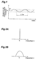
- the period of the amplitude modulation over the light including signals is equal to the period 1/fm of the phase modulation or frequency modulation.
- the average power of the laser light emitted from the semiconductor laser source is indicated by P 1 and the power amplitude of the laser light by a 1 .
- the modulation depth is defined as a 1 /P 1 .
- the spectrum of the laser light emitted from the semiconductor laser source will be one having the shape of a narrow bandwidth around the frequency f 0 , as illustrated in Fig. 2A. If the laser light emitted with the driving current supplied to the semiconductor laser source undergoes direct modulation on the other hand, the spectrum of the laser light emitted from the semiconductor laser source will be one having the shape of a broad bandwidth around the frequency f 0 , as illustrated in Fig. 2B, because of occurrence of chirping due to variation in the refractive index of the waveguide layer in the semiconductor laser source. Then this expansion of the spectral width of laser light makes it possible to suppress the occurrence of SBS.
- the power of the laser light from the semiconductor laser source is low, it is common practice to amplify the laser light once by an optical amplifier and thereafter output the amplified light to the optical transmission line.
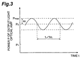
- the light including signals having passed through the optical amplifier (the amplified laser light), as illustrated in Fig. 3, has the average optical power P 2 larger than the average optical power P 1 of the laser light emitted from the semiconductor laser source, the power amplitude of a 2 (> a 1 ), and the modulation depth of a 2 /P 2 . It is noted here that the modulation components from the signal source is omitted from this waveform illustrated in Fig. 3.
- the light including signals outputted from the optical amplifier to the optical transmission line can be regarded as amplitude-modulated light having the average optical power of P 2 and the amplitude of a 2 , and the maximum optical power P max thereof is given by P 2 + a 2 . If this maximum optical power P max exceeds a predetermined threshold (Fig. 4A shows a state in which the maximum optical power P max is over the predetermined threshold L1 in the region indicated by A and Fig. 4 also includes an illustration of the signal components, unlike Fig. 3), the nonlinear optical phenomena, such as four-wave mixing, Self-Phase Modulation (SPM), etc., will become prominent in the optical transmission line and, as illustrated in Fig.
- SPM Self-Phase Modulation
- the signal light after propagation through the long-haul optical transmission line will demonstrate considerable degradation of the waveform due to influence of dispersion in the optical transmission line. This will result in alternate appearance of regions with heavy waveform degradation (regions as indicated by A in Fig. 4A and Fig. 4B) and regions with little waveform degradation in the period of 1/fm on the time axis in the conventional optical communication.
- the present invention has been accomplished in order to solve the above-stated issue and an object of the present invention is thus to provide an optical transmitter having the structure for enabling output of high-power light signals while effectively suppressing occurrence of the nonlinear optical phenomena, particularly, SBS, and an optical communication system equipped therewith.
- An optical transmitter is characterized by comprising a modulation signal source for outputting modulation signals of a predetermined frequency, a semiconductor laser source driven by the modulation signals from the modulation signal source to output laser light modulated according to the modulation signals, an optical amplifier for amplifying the laser light from the semiconductor laser source, and a modulation depth control system for controlling a ratio of an amplitude modulation depth of amplified laser light outputted from the optical amplifier, to an amplitude modulation depth of the laser light inputted into the optical amplifier in the range of 60% or less, preferably, in the range of 10% or less.
- the modulation signal source for supplying the electric signals for driving the above semiconductor laser source is utilized as a signal source for supplying signals to be superimposed on the laser light
- the optical transmitter may also be constructed in structure further comprising a signal source for outputting signals to be transmitted, in the form of an electric signal, and an external modulator which is disposed on a transmission line between the semiconductor laser source and the optical amplifier, which amplitude-modulates the laser light outputted from the semiconductor laser source, based on the electric signals outputted from the signal source, and which outputs the amplitude-modulated laser light as light including signals to the optical amplifier.
- the above optical amplifier may comprise an erbium-doped optical fiber.
- the modulation frequency in the modulation signal source is more preferably in the range of 20 kHz or less.
- the laser light outputted from the semiconductor laser source is amplitude-modulated by the modulation signals of the predetermined frequency (preferably, 20 kHz or less), the high-frequency signal components are superimposed thereon to form the light including signals (in the case of the structure having the external modulator, the signal components are superimposed on the laser light by the external modulator in accordance with the electric signals from the signal source), and these light signals is amplified by the optical amplifier.
- the modulation signals of the predetermined frequency preferably, 20 kHz or less
- the high-frequency signal components are superimposed thereon to form the light including signals (in the case of the structure having the external modulator, the signal components are superimposed on the laser light by the external modulator in accordance with the electric signals from the signal source), and these light signals is amplified by the optical amplifier.
- the modulation depth control system controls the amplitude modulation depth of the amplified laser light outputted from the optical amplifier in the range of 60% or less, preferably, in the range of 10% or less of the amplitude modulation depth of the laser light inputted into the optical amplifier
- the maximum optical power P max of the laser light outputted from the optical amplifier can be kept at or below the level L1 where the waveform degradation becomes unignorable due to the nonlinear optical phenomena (see Fig. 4A) and it can effectively suppress the occurrence of the nonlinear optical phenomena, particularly, SBS in the optical transmission line placed after the optical transmitter while enabling output of high-power light signals.
- the aforementioned modulation depth control system controls either one of a driving system of the semiconductor laser source and a time response element of the optical amplifier, thereby controlling the amplitude modulation depth of the amplified laser light outputted from the optical amplifier in the range of 60% or less, preferably, in the range of 10% or less of the amplitude modulation depth of the laser light inputted into the optical amplifier.
- control operation over the driving system of the semiconductor laser source can be implemented by a control operation to control the modulation frequency to the semiconductor laser source and the signal intensities of the driving signals, and the control operation over the time response element of the optical amplifier by a control operation to control a parameter ⁇ (response speed of population inversion) of the amplifying optical fiber in the optical amplifier (i.e., by selection of the amplifying optical fiber applied to the optical amplifier), or by a control operation to control a time constant of a circuit element in the optical amplifier.
- ⁇ response speed of population inversion
- An optical communication system comprises the above-stated optical transmitter for outputting light signals, an optical transmission line through which the light signals outputted from the optical transmitter propagates, and an optical receiver for receiving the light signals having propagated through the optical transmission line.
- the light signals outputted from the optical transmitter travels through the optical transmission line to the optical receiver to be received thereby. Since the above-stated optical transmitter is applied to this system, it can suppress the occurrence of the nonlinear optical phenomena, particularly, SBS in the optical transmission line and transmit the light signals of high power, thus decreasing the reception errors at the optical receiver.
- Fig. 5A is a diagram to show the structure of the first embodiment of the optical transmitter and the optical communication system provided therewith according to the present invention, and the optical communication system according to the first embodiment is provided with an optical fiber transmission line 20, an optical transmitter 10a disposed on the input end side of the optical fiber transmission line 20, and an optical receiver 30 disposed on the output end side of the optical fiber transmission line 20.
- the optical transmitter 10a is constructed to perform the modulation operation over the laser light of a carrier wave and the superposition operation of the signal components simultaneously and, specifically, the optical transmitter 10a comprises a modulation signal source 11 functioning to output the modulation signals of the frequency fm and also functioning as a signal source, a semiconductor laser source 12 (LD) for outputting the laser light (including the signal components) phase-modulated or frequency-modulated and also amplitude-modulated, based on the modulation signals, an optical amplifier 13 for amplifying the laser light outputted from the semiconductor laser source 2, as light including signals, and a modulation depth control system for controlling the amplitude modulation depth of the amplified laser light outputted from the optical amplifier in the range of 60% or less, preferably, in the range of 10% or less of the amplitude modulation depth of the laser light inputted into the optical amplifier.
- a modulation signal source 11 functioning to output the modulation signals of the frequency fm and also functioning as a signal source
- LD semiconductor laser source 12
- an optical amplifier 13 for
- Fig. 5B is a diagram to show the structure of the second embodiment of the optical transmitter and the optical communication system provided therewith according to the present invention, and the optical communication system according to the second embodiment is provided with the optical fiber transmission line 20, the optical transmitter 10b disposed on the input end side of the optical fiber transmission line, and the optical receiver 30 disposed on the output end side of the optical fiber transmission line 20.
- the optical transmitter 10b is constructed of separate mechanisms for outputting the laser light of the carrier wave and for superimposing the high-frequency signals thereon and, specifically, it has the modulation signal source 11, the semiconductor laser source 12 (LD), the optical amplifier 13, and the modulation depth control system 14 and further has a signal source 15 for outputting the signals to be transmitted, in the form of an electric signal, and an external modulator 16 which is disposed on the transmission line between the semiconductor laser source 12 and the optical amplifier 13, which amplitude-modulates the laser light outputted from the semiconductor laser source 12, based on the electric signals outputted from the signal source 15, and which outputs the amplitude-modulated laser light as the light including signals to the optical amplifier 13.
- the modulation signal source 11 the semiconductor laser source 12 (LD), the optical amplifier 13, and the modulation depth control system 14
- a signal source 15 for outputting the signals to be transmitted, in the form of an electric signal
- an external modulator 16 which is disposed on the transmission line between the semiconductor laser source 12 and the optical amplifier 13, which amplitude-modulates the laser light
- the modulation signal source 11 outputs the modulation signals of the frequency fm, for example, 20 kHz or less to the semiconductor laser source 12.
- the semiconductor laser source 12 is driven by the modulation signals of the frequency fm outputted from the modulation signal source 11 and outputs the laser light amplitude-modulated while phase-modulated or frequency-modulated according to the modulation signals.
- the wavelength band of this laser light is preferably the 1.55 ⁇ m wavelength band, for example.
- the signal source 15 outputs the signal components to be transmitted, in the form of the electric signal.
- the external modulator 16 amplitude-modulates the laser light outputted from the semiconductor laser source 12, based on the electric signal outputted from the signal source 15, and outputs the amplitude-modulated laser light as the light including signals.
- the optical amplifier 13 amplifies the signal light outputted from the external modulator 16 and outputs the amplified light including signals to the optical transmission line 20.
- the optical amplifier 13 is preferably an erbium-doped optical fiber amplifier which has an amplifying optical fiber with the core region doped with the element Er or the like, and a pumping source for supplying pumping light of a predetermined wavelength to the amplifying optical fiber. The reason is that it becomes easier to control the modulation depth of the light including signals outputted from the optical amplifier 13, because the response characteristic of population inversion is relatively low in the amplifying optical fiber where the optical amplifier 13 is the erbium-doped optical fiber amplifier.
- the modulation depth control system 14 controls at least either one of the driving system (modulation signal source 11) of the semiconductor laser source 12 and the time response element of the optical amplifier 13, thereby controlling the amplitude modulation depth of the amplified laser light (frequency fm) outputted from the optical amplifier in the range of 60% or less, preferably, in the range of 10% or less of the amplitude modulation depth of the laser light inputted into the optical amplifier.
- the signal light outputted from the optical amplifier 13 of the optical transmitter 10b propagates through the optical transmission line 20 to reach the optical receiver 30.
- the optical receiver 30 receives these light signals thus arriving.
- the signal light can be transmitted from the optical transmitter 10 through the optical transmission line 20 to the optical receiver 30 with effectively suppressing the occurrence of SBS and avoiding the degradation of the signal waveform, even in high-speed optical transmission over 1 Gbs.
- the occurrence of nonlinear optical phenomena becomes conspicuous in the optical transmission line 20.
- the occurrence of SBS can be effectively restrained (the waveform degradation of light including signals can be avoided) even if the optical power of the light including signals outputted to the optical transmission line 20 is 7 dBm or more.
- the optical transmitters 10a, 10b according to the present invention can effectively suppress the occurrence of SBS even if the value of ⁇ N2>/A eff is 6 ⁇ 10 -10 /W or more at the input end of the optical transmission line 20.
- E represents the electric field caused by the propagating light and r the radial distance from the center of the core.
- the response of the optical amplifier 13 to the modulation waveform (the modulation components of the frequency fm from the modulation signal source 11) of the inputted light including signals is reduced to temporal behavior of population inversion (gain coefficient) in the laser medium of the optical amplifier 13 upon input of light signals.
- the response speed of population inversion in the laser medium of the optical amplifier 13 is dominated by the effective lifetime ⁇ eff of the higher energy state of the laser medium expressed by the following equation.
- ⁇ eff ⁇ /(1 + I/I s + I p /I pth )
- ⁇ is the lifetime of the higher energy state in the amplifying optical fiber under absence of light
- I the intensity of the inputted light including signals
- I s the saturation intensity of the inputted light including signals
- I p the intensity of the pumping light
- I pth the threshold intensity of the pumping light where the laser medium of the optical amplifier 13 becomes transparent.
- the frequency fm of the amplitude modulation (the modulation components from the modulation signal source 11) of the light including signals inputted into the optical amplifier 13 is relatively low, i.e., when the period 1/fm of the amplitude modulation is longer than the effective lifetime ⁇ eff of the higher energy state, the population inversion (gain coefficient) in the optical amplifier 13 can follow variation in the intensity of the light including signals inputted into the optical amplifier 13.
- the light including signals outputted from the optical amplifier 13 demonstrates a decrease of the modulation depth; the modulation depth at the input end is decreased to that at the output end, as illustrated in Fig. 6B and Fig. 6C, or the modulation amplitude becomes almost zero (continuous light).
- FIG. 6B is a diagram to show the waveform of the light including signals at the part (input end) indicated by A1 in Fig. 6A showing the optical amplifier
- Fig. 6C a diagram to show the waveform of the light including signals at the part (output end) indicated by B1 in Fig. 6A.
- the frequency fm of the amplitude modulation (the modulation components from the modulation signal source 11) of the light including signals inputted into the optical amplifier 13 is relatively high, i.e., when the period 1/fm of the amplitude modulation is shorter than the effective lifetime ⁇ eff of the higher energy state, the population inversion (gain coefficient) in the optical amplifier 13 becomes unable to follow the variation in the intensity of the inputted light including signals, so that the optical amplifier 13 comes to have an almost constant gain coefficient according to the average intensity of the inputted light including signals.
- Fig. 7C is a diagram to show the waveform of the light including signals at the part (input end) indicated by A2 in Fig. 7A showing the optical amplifier
- Fig. 7C a diagram to show the waveform of the light including signals at the part (output end) indicated by B2 in Fig. 7A showing the optical amplifier.
- the modulation components (signal components) from the signal source 3 is omitted from the illustration of the waveform in each of above Fig. 6B, Fig. 6C, Fig. 7B, and Fig. 7C.
- the change of the intensity I of the light including signals makes little contribution to the value of the effective lifetime ⁇ eff of the higher energy state (or is negligible).
- the intensity I of the inputted light including signals becomes approximately equal to or larger than the saturation intensity I s , i.e., when the optical amplifier 13 is operated near the saturation intensity, the change of the intensity I of the inputted light including signals comes to make great contribution to the value of the effective lifetime ⁇ eff of the higher energy state. Therefore, the occurrence of SBS in the optical transmission line will pose a problem in the ordinary optical communication systems in which the optical amplifier 13 is operated near the saturation intensity.
- Fig. 8A and Fig. 8B are diagrams to show the spectra of the laser light where the modulation frequency fm is 1 kHz and the modulation depth is 20%, wherein Fig. 8A is a diagram to show the laser light spectrum before input into the optical amplifier 13 (the spectrum of the light including signals before amplification) and Fig. 8B a diagram to show the laser light spectrum after passage through the optical amplifier 13 (the spectrum of the light including signals after amplification). As seen from these diagrams, the sideband component corresponding to the modulation frequency fm disappeared from the light including signals outputted from the optical amplifier 13.
- Fig. 9A and Fig. 9B are diagrams to show laser light spectra where the modulation frequencies fm are 7 kHz and 20 kHz and the modulation depth is 20%
- Fig. 9A is a diagram to show the laser light spectrum before input into the optical amplifier 13 (the spectrum of the light including signals before amplification)
- Fig. 9B a diagram to show the laser light spectrum after passage through the optical amplifier 13 (the spectrum of the light including signals after amplification).
- the component of the modulation frequency of 7 kHz disappeared but the components of the modulation frequency of 20 kHz remained in the light including signals outputted from the optical amplifier 13.
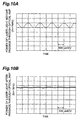
- Fig. 10A and Fig. 10B are diagrams to show the time waveforms of the laser light where the modulation frequency fm is 1 kHz and the modulation depth is 10%
- Fig. 10A is a diagram to show the time waveform of the laser light before input into the optical amplifier 13 (the waveform of the light including signals before amplification)
- Fig. 10B a diagram to show the time waveform of the laser light after passage through the optical amplifier 13 (the waveform of the light including signals after amplification).
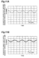
- Fig. 11A and Fig. 11B are diagrams to show the time waveforms of the laser light where the modulation frequency fm is 40 kHz and the modulation depth is 10%, wherein Fig.
- FIG. 11A is a diagram to show the time waveform of the laser light before input into the optical amplifier 13 (the waveform of the light including signals before amplification) and Fig. 11B a diagram to show the time waveform of the laser light after passage through the optical amplifier 13 (the waveform of the light including signals after amplification).
- the modulation depth of the light including signals outputted from the optical amplifier 13 demonstrates a definite decrease where the modulation frequency fm is 1 kHz. In contrast with it, where the modulation frequency fm is 40 kHz, the modulation depth of the light including signals outputted from the optical amplifier 13 is almost equal to that of the light including signals inputted into the optical amplifier 13 (the light including signals before amplification).
- Fig. 12 is a graph to show an example of relationship between modulation frequency fm and modulation depth residue.
- the modulation depth residue herein is a ratio of the modulation depth of the light including signals amplitude-modulated at the frequency fm and outputted from the optical amplifier 13, to the modulation depth of the light including signals amplitude-modulated at the frequency fm and inputted into the optical amplifier 13. As seen from this graph, the smaller the modulation frequency fm, the smaller the modulation depth residue.
- the modulation depth residue is 60% or less in the range of the modulation frequency fm of 20 kHz or less, the modulation depth residue is 30% or less in the range of the modulation frequency fm of 10 kHz or less, and the modulation depth residue is 15% or less in the range of the modulation frequency fm of 5 kHz or less.
- Fig. 13 is a graph to show the relationship between optical power of the light including signals outputted from the optical amplifier 13 to the optical transmission line 20 (power of incident light) and optical power of the reflected components from the optical transmission line 20 (power of reflected light).
- Graphs G100, G200, and G300 represent results of measurement where the optical transmission line 20 was a 20km-long single-mode optical fiber (without superposition of the high-frequency signal components).
- graph G100 shows the results of measurement under the setting where the modulation frequency fm was 0 (no modulation)
- graph G200 the results of measurement under the setting where the modulation frequency fm was 1 kHz and the modulation depth was 10%
- graph G300 the results of measurement under the setting where the modulation frequency fm was 5 kHz and the modulation depth was 10%.
- the SBS occurs less with increase in the modulation frequency fm.
- the modulation frequency fm of the laser light by the modulation signal source 11 is set preferably to be smaller than the reciprocal of the effective lifetime ⁇ eff of the higher energy state of the laser medium.
- the SBS suppression effect can be enhanced effectively by increasing the modulation frequency fm of the laser light by the modulation signal source 11.
- the present invention has been accomplished based on the considerations and knowledge as described above, and such modulation depth control operation is carried out by the modulation depth control system 14.
- optical communication system of the first embodiment has the structure illustrated in Fig. 5A, as described previously
- the optical communication system according to the second embodiment has the structure illustrated in Fig. 5B, as described previously.
- the optical transmission line 20 is a 200km-long single-mode optical fiber or a 200km-long dispersion-shifted optical fiber disposed between the optical transmitter 10a, 10b and the optical receiver 30.
- the optical power of the light including signals outputted from the optical transmitter 10a, 10b to the optical transmission line 20 is +15 dBm.
- the present invention provides the optical transmitter with the structure in which the laser light modulated by the modulation signals of the predetermined frequency (preferably, 20 kHz or less) undergoes such control that the ratio of the amplitude modulation depth of the laser light outputted from the optical amplifier to the amplitude modulation depth of the laser light outputted from the semiconductor laser source falls in the range of 60% or less, preferably, in the range of 10% or less, whereby the occurrence of the nonlinear optical phenomena, particularly, SBS can be effectively suppressed in the optical transmission line in which the laser light outputted from the optical amplifier (the amplified light including signals) propagates, thus enabling the output of high-power light signals.
- the predetermined frequency preferably, 20 kHz or less
- the modulation depth of the light including signals outputted to the optical transmission line is controlled within the desired range in the optical communication system to which the optical transmitter having the structure as described above is applied, the occurrence of nonlinear optical phenomena, particularly, SBS can be suppressed effectively in the optical transmission line and the high-power light signals can be transmitted therethrough; therefore, the reception errors are reduced at the optical transmitter.
Landscapes
- Physics & Mathematics (AREA)
- Optics & Photonics (AREA)
- Electromagnetism (AREA)
- Engineering & Computer Science (AREA)
- Computer Networks & Wireless Communication (AREA)
- Signal Processing (AREA)
- Optical Communication System (AREA)
- Semiconductor Lasers (AREA)
- Lasers (AREA)
Abstract
Description

Claims (11)
- An optical transmitter comprising:wherein a ratio of an amplitude modulation depth of amplified laser light outputted from the optical amplifier, to an amplitude modulation depth of the laser light inputted into said optical amplifier, is set in the range of 60% or less.a modulation signal source for outputting modulation signals of a predetermined frequency;a semiconductor laser source driven by said modulation signals outputted from said modulation signal source to output laser light modulated according to said modulation signals; andan optical amplifier for amplifying the laser light from said semiconductor laser source,
- An optical transmitter comprising:a modulation signal source for outputting modulation signals of a predetermined frequency;a semiconductor laser source driven by said modulation signals outputted from said modulation signal source to output laser light modulated according to said modulation signals;an optical amplifier for amplifying the laser light from said semiconductor laser source; anda modulation depth control system for controlling a ratio of an amplitude modulation depth of amplified laser light outputted from the optical amplifier, to an amplitude modulation depth of the laser light inputted into said optical amplifier in the range of 60% or less.
- The optical transmitter according to Claim 1 or 2, further comprising:a signal source for outputting signals to be transmitted, in the form of an electric signal; andan external modulator which is provided on a transmission line between said semiconductor laser source and said optical amplifier, which amplitude-modulates the laser light outputted from the semiconductor laser source, based on the electric signals outputted from said signal source, and which outputs the amplitude-modulated laser light as light including signals to said optical amplifier.
- The optical transmitter according to Claim 1 or 2, wherein said predetermined frequency is 20 kHz or less.
- The optical transmitter according to Claim 1 or 2, wherein said optical amplifier comprises an erbium-doped optical fiber.
- An optical communication system comprising:the optical transmitter as set forth in Claim 1 or 2;an optical transmission line through which light signals outputted from said optical transmitter propagates; andan optical receiver for receiving said light signals having propagated through said optical transmission line.
- An optical transmitter comprising:wherein a ratio of an amplitude modulation depth of amplified laser light outputted from the optical amplifier, to an amplitude modulation depth of the laser light inputted into said optical amplifier, is set in the range of 10% or less.a modulation signal source for outputting modulation signals of a frequency not more than 20 kHz;a semiconductor laser source driven by said modulation signals outputted from said modulation signal source to output laser light modulated according to said modulation signals; andan optical amplifier for amplifying the laser light from said semiconductor laser source,
- An optical transmitter comprising:a modulation signal source for outputting modulation signals of a frequency not more than 20 kHz;a semiconductor laser source driven by said modulation signals outputted from said modulation signal source to output laser light modulated according to said modulation signals;an optical amplifier for amplifying the laser light from said semiconductor laser source; anda modulation depth control system for controlling a ratio of an amplitude modulation depth of amplified laser light outputted from the optical amplifier, to an amplitude modulation depth of the laser light inputted into said optical amplifier in the range of 10% or less.
- The optical transmitter according to Claim 7 or 8, further comprising:a signal source for outputting signals to be transmitted, in the form of an electric signal; andan external modulator which is provided on a transmission line between said semiconductor laser source and said optical amplifier, which amplitude-modulates the laser light outputted from the semiconductor laser source, based on the electric signals outputted from said signal source, and which outputs the amplitude-modulated laser light as light including signals to said optical amplifier.
- The optical transmitter according to Claim 7 or 8, wherein said optical amplifier comprises an erbium-doped optical fiber.
- An optical communication system comprising:the optical transmitter as set forth in Claim 7 or 8;an optical transmission line through which light signals outputted from said optical transmitter propagates; andan optical receiver for receiving said light signals having propagated through said optical transmission line.
Applications Claiming Priority (3)
| Application Number | Priority Date | Filing Date | Title |
|---|---|---|---|
| JP10544999 | 1999-04-13 | ||
| JP11105449A JP2000299525A (en) | 1999-04-13 | 1999-04-13 | Optical transmitter and optical communication system |
| PCT/JP2000/001014 WO2000062382A1 (en) | 1999-04-13 | 2000-02-23 | Optical transmitter and optical transmission system comprising the same |
Publications (2)
| Publication Number | Publication Date |
|---|---|
| EP1178580A1 true EP1178580A1 (en) | 2002-02-06 |
| EP1178580A4 EP1178580A4 (en) | 2006-05-10 |
Family
ID=14407909
Family Applications (1)
| Application Number | Title | Priority Date | Filing Date |
|---|---|---|---|
| EP00905276A Withdrawn EP1178580A4 (en) | 1999-04-13 | 2000-02-23 | OPTICAL TRANSMITTER AND THIS CONTAINING OPTICAL SENDING SYSTEM |
Country Status (7)
| Country | Link |
|---|---|
| US (1) | US7103285B1 (en) |
| EP (1) | EP1178580A4 (en) |
| JP (1) | JP2000299525A (en) |
| AU (1) | AU2689600A (en) |
| CA (1) | CA2372080A1 (en) |
| TW (1) | TW459448B (en) |
| WO (1) | WO2000062382A1 (en) |
Cited By (3)
| Publication number | Priority date | Publication date | Assignee | Title |
|---|---|---|---|---|
| CN1316767C (en) * | 2003-01-03 | 2007-05-16 | 华为技术有限公司 | Method for reducing Brillonin scattering effect influence excited in optical transmission system |
| GB2474455A (en) * | 2009-10-14 | 2011-04-20 | Coreoptics Inc | Directly modulating the current of a laser and externally modulating the amplitude of the laser output |
| CN110426373A (en) * | 2019-07-16 | 2019-11-08 | 南昌航空大学 | A kind of method of Brillouin scattering and optical coherence elastogram in situ detection |
Families Citing this family (12)
| Publication number | Priority date | Publication date | Assignee | Title |
|---|---|---|---|---|
| US7603045B2 (en) * | 2003-08-28 | 2009-10-13 | Fujitsu Limited | Method and system for automatic feedback control for fine tuning a delay interferometer |
| JP2005086782A (en) * | 2003-09-11 | 2005-03-31 | Central Res Inst Of Electric Power Ind | Composite modulation method, separation method of composite modulated optical signal, and composite modulation type radio base station |
| JP4912971B2 (en) * | 2007-07-02 | 2012-04-11 | 株式会社精工技研 | Optical transmitter and optical transmission system |
| JP2010011098A (en) * | 2008-06-27 | 2010-01-14 | Fujitsu Ltd | Optical transmission device |
| CA2743648C (en) * | 2008-11-21 | 2014-11-04 | Institut National D'optique | Spectrally tailored pulsed fiber laser oscillator |
| US8630036B2 (en) * | 2009-10-30 | 2014-01-14 | Deep Photonics Corporation | Method and system using phase modulation to reduce spectral broadening |
| EP3408951B1 (en) * | 2016-01-25 | 2021-06-30 | Telefonaktiebolaget LM Ericsson (publ) | Methods and apparatus for multiplexing signals |
| JP6911483B2 (en) | 2017-04-19 | 2021-07-28 | 富士通株式会社 | Wavelength converter, controlled light generator, wavelength conversion method, and controlled light generator |
| FR3078598B1 (en) * | 2018-03-01 | 2020-02-07 | Thales | DUAL BAND FREQUENCY CONVERSION PHOTONIC DEVICE AND METHOD |
| CN108802425A (en) * | 2018-07-27 | 2018-11-13 | 成都信息工程大学 | A kind of airborne measuring wind speed laser radar system |
| CN113161858B (en) * | 2021-03-25 | 2024-02-23 | 武汉光谷航天三江激光产业技术研究院有限公司 | A method and device for high-power single-frequency laser output |
| CN115219457A (en) * | 2022-07-19 | 2022-10-21 | 北京计算机技术及应用研究所 | Graphene heterojunction-based semiconductor material exciton resonance absorption modulation system |
Family Cites Families (13)
| Publication number | Priority date | Publication date | Assignee | Title |
|---|---|---|---|---|
| DE4234599A1 (en) * | 1992-08-22 | 1994-02-24 | Sel Alcatel Ag | Optical transmitter |
| JP3434869B2 (en) * | 1994-02-07 | 2003-08-11 | 株式会社日立製作所 | Optical regenerative repeater and optical transmission device |
| US5477368A (en) * | 1994-12-29 | 1995-12-19 | At&T Corp. | High power lightwave transmitter using highly saturated amplifier for residual AM suppression |
| US5835655A (en) | 1995-01-26 | 1998-11-10 | Corning Incorporated | Large effective area waveguide fiber |
| JPH0923187A (en) | 1995-07-10 | 1997-01-21 | Fujitsu Ltd | Optical transmission system |
| IT1276024B1 (en) * | 1995-10-12 | 1997-10-24 | Pirelli Cavi S P A Ora Pirelli | POLARIZATION SYSTEM OF AN OPTICAL CABLE MODULATOR |
| JPH09139715A (en) * | 1995-11-16 | 1997-05-27 | Fujitsu Ltd | Optical transmitter |
| JPH09205399A (en) * | 1996-01-29 | 1997-08-05 | Nippon Telegr & Teleph Corp <Ntt> | Optical transmitter |
| JP3405046B2 (en) * | 1996-02-22 | 2003-05-12 | Kddi株式会社 | Laser light generator |
| US6252692B1 (en) * | 1996-06-07 | 2001-06-26 | Nortel Networks Limited | Optical fibre transmission systems |
| JPH10163974A (en) * | 1996-11-25 | 1998-06-19 | Fujitsu Ltd | Optical transmitter and optical communication system |
| JPH10164024A (en) * | 1996-12-05 | 1998-06-19 | Nec Corp | Optical transmitter for WDM transmission |
| US6078417A (en) * | 1997-05-29 | 2000-06-20 | Lucent Technologies Inc. | Spectral compaction via cross-modulation wavelength conversion |
-
1999
- 1999-04-13 JP JP11105449A patent/JP2000299525A/en active Pending
-
2000
- 2000-02-23 WO PCT/JP2000/001014 patent/WO2000062382A1/en not_active Ceased
- 2000-02-23 EP EP00905276A patent/EP1178580A4/en not_active Withdrawn
- 2000-02-23 AU AU26896/00A patent/AU2689600A/en not_active Abandoned
- 2000-02-23 CA CA002372080A patent/CA2372080A1/en not_active Abandoned
- 2000-04-10 TW TW089106606A patent/TW459448B/en not_active IP Right Cessation
- 2000-10-26 US US09/696,030 patent/US7103285B1/en not_active Expired - Fee Related
Cited By (4)
| Publication number | Priority date | Publication date | Assignee | Title |
|---|---|---|---|---|
| CN1316767C (en) * | 2003-01-03 | 2007-05-16 | 华为技术有限公司 | Method for reducing Brillonin scattering effect influence excited in optical transmission system |
| GB2474455A (en) * | 2009-10-14 | 2011-04-20 | Coreoptics Inc | Directly modulating the current of a laser and externally modulating the amplitude of the laser output |
| CN110426373A (en) * | 2019-07-16 | 2019-11-08 | 南昌航空大学 | A kind of method of Brillouin scattering and optical coherence elastogram in situ detection |
| CN110426373B (en) * | 2019-07-16 | 2021-11-26 | 南昌航空大学 | In-situ detection method for Brillouin scattering and optical coherence elastography |
Also Published As
| Publication number | Publication date |
|---|---|
| WO2000062382A1 (en) | 2000-10-19 |
| TW459448B (en) | 2001-10-11 |
| JP2000299525A (en) | 2000-10-24 |
| AU2689600A (en) | 2000-11-14 |
| EP1178580A4 (en) | 2006-05-10 |
| US7103285B1 (en) | 2006-09-05 |
| CA2372080A1 (en) | 2000-10-19 |
Similar Documents
| Publication | Publication Date | Title |
|---|---|---|
| EP0720313B1 (en) | High power lightwave transmitter using highly saturated amplifier for residual AM suppression | |
| JP3036876B2 (en) | Optical transmitter | |
| US6078414A (en) | Optical transmitter system | |
| EP0595536B1 (en) | Reduction of stimulated brillouin scattering in a fiber optic transmission system | |
| US7103285B1 (en) | Optical transmission system for reducing nonlinear optical phenomena using modulation depth control system | |
| EP1079552A2 (en) | Method, optical device, and system for optical fiber transmission | |
| US7127182B2 (en) | Efficient optical transmission system | |
| US7639955B2 (en) | Method and apparatus for transmitting a signal using a chirp managed laser (CML) and an optical spectrum reshaper (OSR) before an optical receiver | |
| JP2006517772A (en) | Optical transmitter with SBS suppression | |
| Downie et al. | 40× 112 Gb/s transmission over an unrepeatered 365 km effective area-managed span comprised of ultra-low loss optical fibre | |
| JP2839105B2 (en) | High-speed optical communication system for long distance | |
| US6867905B1 (en) | Reduced four-wave mixing and raman amplification architecture | |
| JP2004289811A (en) | Optical transmission system | |
| US8538218B2 (en) | Unrepeatered long haul optical fiber transmission systems | |
| US20030223763A1 (en) | Optical transmitter and optical communication system | |
| Chandrasekhar et al. | Repeaterless transmission with negative penalty over 285 km at 10 Gb/s using a chirp managed laser | |
| Brandon et al. | Raman limited, truly unrepeatered transmission at 2.5 Gbit/s over 453 km with+ 30 dBm launch signal power | |
| JP3162185B2 (en) | Optical fiber communication system | |
| Chi et al. | Stimulated Brillouin scattering suppressed EDFA in a long-haul optical fiber link system | |
| JPWO2000062382A1 (en) | Optical transmitter and optical communication system including the same | |
| JPH05333389A (en) | Optical transmission system and optical amplifier | |
| Sugie | Maximum repeaterless transmission of lightwave systems imposed by stimulated Brillouin scattering in fibres | |
| JP2002152134A (en) | Metro modulation WDM system with direct modulation | |
| Eskildsen et al. | 465-km repeaterless transmission using a 2.488 Gb/s directly modulated DFB laser | |
| 王晖 | Experimental Study on Stimulated Brillouin Scattering Effect in Single Mode Fiber Transmission System |
Legal Events
| Date | Code | Title | Description |
|---|---|---|---|
| PUAI | Public reference made under article 153(3) epc to a published international application that has entered the european phase |
Free format text: ORIGINAL CODE: 0009012 |
|
| 17P | Request for examination filed |
Effective date: 20011112 |
|
| AK | Designated contracting states |
Kind code of ref document: A1 Designated state(s): AT BE CH CY DE DK ES FI FR GB GR IE IT LI LU MC NL PT SE |
|
| RBV | Designated contracting states (corrected) |
Designated state(s): DE FR GB IT |
|
| A4 | Supplementary search report drawn up and despatched |
Effective date: 20060323 |
|
| RIC1 | Information provided on ipc code assigned before grant |
Ipc: H01S 3/10 20060101AFI20001025BHEP Ipc: H01S 5/0687 20060101ALI20060317BHEP Ipc: H04B 10/155 20060101ALI20060317BHEP Ipc: H01S 3/067 20060101ALI20060317BHEP |
|
| STAA | Information on the status of an ep patent application or granted ep patent |
Free format text: STATUS: THE APPLICATION IS DEEMED TO BE WITHDRAWN |
|
| 18D | Application deemed to be withdrawn |
Effective date: 20061114 |