EP1178481A1 - Device for recording or reproducing signals on disk and method of inserting and extracting cartridge for the device - Google Patents
Device for recording or reproducing signals on disk and method of inserting and extracting cartridge for the device Download PDFInfo
- Publication number
- EP1178481A1 EP1178481A1 EP00909777A EP00909777A EP1178481A1 EP 1178481 A1 EP1178481 A1 EP 1178481A1 EP 00909777 A EP00909777 A EP 00909777A EP 00909777 A EP00909777 A EP 00909777A EP 1178481 A1 EP1178481 A1 EP 1178481A1
- Authority
- EP
- European Patent Office
- Prior art keywords
- cartridge
- holder
- shutter
- loading
- latch
- Prior art date
- Legal status (The legal status is an assumption and is not a legal conclusion. Google has not performed a legal analysis and makes no representation as to the accuracy of the status listed.)
- Withdrawn
Links
- 238000000034 method Methods 0.000 title claims description 3
- 238000005452 bending Methods 0.000 description 3
- 210000000078 claw Anatomy 0.000 description 3
- 239000002184 metal Substances 0.000 description 3
- 238000009877 rendering Methods 0.000 description 2
- 238000010276 construction Methods 0.000 description 1
- 239000000428 dust Substances 0.000 description 1
Images




Classifications
-
- G—PHYSICS
- G11—INFORMATION STORAGE
- G11B—INFORMATION STORAGE BASED ON RELATIVE MOVEMENT BETWEEN RECORD CARRIER AND TRANSDUCER
- G11B17/00—Guiding record carriers not specifically of filamentary or web form, or of supports therefor
- G11B17/02—Details
- G11B17/04—Feeding or guiding single record carrier to or from transducer unit
-
- G—PHYSICS
- G11—INFORMATION STORAGE
- G11B—INFORMATION STORAGE BASED ON RELATIVE MOVEMENT BETWEEN RECORD CARRIER AND TRANSDUCER
- G11B17/00—Guiding record carriers not specifically of filamentary or web form, or of supports therefor
- G11B17/02—Details
- G11B17/04—Feeding or guiding single record carrier to or from transducer unit
- G11B17/041—Feeding or guiding single record carrier to or from transducer unit specially adapted for discs contained within cartridges
- G11B17/044—Indirect insertion, i.e. with external loading means
- G11B17/046—Indirect insertion, i.e. with external loading means with pivoting loading means
-
- G—PHYSICS
- G11—INFORMATION STORAGE
- G11B—INFORMATION STORAGE BASED ON RELATIVE MOVEMENT BETWEEN RECORD CARRIER AND TRANSDUCER
- G11B17/00—Guiding record carriers not specifically of filamentary or web form, or of supports therefor
- G11B17/02—Details
- G11B17/04—Feeding or guiding single record carrier to or from transducer unit
- G11B17/041—Feeding or guiding single record carrier to or from transducer unit specially adapted for discs contained within cartridges
- G11B17/044—Indirect insertion, i.e. with external loading means
- G11B17/046—Indirect insertion, i.e. with external loading means with pivoting loading means
- G11B17/0466—Indirect insertion, i.e. with external loading means with pivoting loading means with opening mechanism of the cartridge shutter
Definitions
- the present invention relates to recording or playback devices for disks accommodated in cartridges, and to a method of loading the cartridge into the device and unloading the cartridge therefrom.
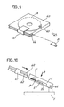
- FIG. 9 is a perspective view of a cartridge 60 having a disk 6 accommodated therein [see JP-B No. 7-36261 (1995)].
- the cartridge 60 is provided in one side portion thereof with a groove 62, with a shutter 61 fitted thereover.
- the cartridge 60 has an upper surface marked with an arrow 63 indicating the direction in which the cartridge 60 is to be loaded into the recording or playback device.
- the shutter 61 is held closed by a lock claw (not shown) within the cartridge 60.
- FIG. 10 is a side elevation showing a conventional disk recording or playback device
- FIGS. 11A and 11B are views in section of the device as it is seen from the direction B.
- a support plate 20 projecting outward from the holder 2 is a kickout member 5 which is slidable along the cartridge loading and unloading directions.
- the kickout member 5 has a contact piece 50 projecting therefrom into a path of movement of the cartridge 60 and pushable by the front end of the cartridge 60.
- the kickout member 5 is biased in the cartridge unloading direction by a spring 8 extending between this member and the holder 2.
- the opening piece 31 is provided inside the holder 2.
- the cartridge loading direction will be referred to as forward.
- the cartridge 60 is loaded into the holder 2 in the state shown in FIG. 11A while pushing the kickout member 5 against the spring 8 on the member 5.
- the opening piece 31 comes into contact with the front edge of the shutter 61, opening the shutter 61 with the loading of the cartridge 60.
- the kickout member 5 is engaged with the holder 2 by a latch mechanism (not shown), holding the cartridge 60 loaded in the holder as seen in FIG. 11B.
- the contact piece 50 pushes the cartridge 60 in the direction of unloading the cartridge from the holder 2 by being biased by the spring 8 on the kickout member 5.
- the present applicant proposed a cartridge 60 wherein a torsion spring 66 is provided between the shutter 61 and the cartridge 60 for automatically closing the shutter 61 as shown in FIG. 3.
- the applicant conceived the idea that if the cartridge 60 is unloaded with use of the biasing force of the torsion spring 66 of the proposed cartridge 60, this eliminates the need to provide the separate member for kicking out the cartridge 60 from the holder 2, whereby the cartridge unloading mechanism can be simplified.
- An object of the present invention is to provide a simplified cartridge unloading mechanism for use in recording or playback devices adapted for use with cartridges having a shutter biased in the closing direction, the mechanism further being adapted to close the shutter reliably.
- the present invention provides a device which is adapted for use with a cartridge 60 having a disk 6 accommodated therein and a shutter 61 biased in a closing direction at all times by a spring 66 disposed inside the cartridge and wherein a holder 2 is provided with a latch 30 movable in a cartridge loading direction for holding the cartridge 60 in a completely loaded position by light engagement therewith.
- the cartridge is loaded by the steps of:
- the cartridge is unloaded by the steps of:
- FIG. 3 is a perspective view showing a cartridge 60 (not disclosed) prepared by the present applicant as a trial.
- the cartridge 60 has a groove 62 in one side portion thereof and a recessed portion 65 in its upper surface.
- a shutter 61 is slidably disposed in the recessed portion 65 and fitted over the groove 62.
- the shutter 61 is biased in a closing direction by a torsion spring 66 inside the cartridge 60. Even if inadvertently opens, the shutter 61 is closed automatically.
- a caved portion 64 is formed in the bottom wall of the cartridge 60.
- a slide member 3 is engageable in the caved portion 64 as will be described later. While the shutter 61 is in an opened state, a disk 6 within the cartridge 60 is partly exposed for recording or reproducing signals.
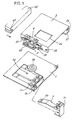
- FIG. 1 is an exploded perspective view of a disk recording or playback device.
- a holder 2 is pivoted at one end thereof to a chassis 1 provided with a pickup 72, and the cartridge 60 is inserted into the holder 2.
- the pickup 72 is movable toward or away from a turntable 73.
- a bracket 71 is attached to the bottom face of the pickup 72.
- a head lever 7 provided with a recording head 70 at an outer end thereof is pivoted at a base end thereof to the bracket 71.
- the head lever 7 is advanced by a lift mechanism (not shown) into the holder 2 through an opening 26 formed in an upper wall of the holder 2.
- the disk 6 in the cartridge 60 is accessible by the recording head 70 for signal recording as in the prior art.
- a change-over piece 10 formed by bending a metal plate and having a projecting upper plate 11 is provided at one corner of the front end of the chassis 1.
- a receiving plate 27 extends inward from the lower end of side plate of the holder 2.
- the cartridge 60 is supported at its bottom on the receiving plate 27.
- a support plate 20 extends outward from the lower end of one side portion of the holder 2.
- a slide member 3 is slidably supported by the support plate 20.
- FIG. 2 is an exploded perspective view of the holder 2 and the slide member 3.
- a pin 28 projecting from the support plate 20 is fitted in a slit 33 of the slide member 3 to render the slide member 3 movable in cartridge loading and unloading directions.
- a lock slide 4 is disposed above the slide member 3. Pins 29, 29 projecting from the upper wall of the holder 2 are fitted in respective slits 44, 44 in the lock slide 4, rendering the lock slide 4 movable in the cartridge loading and unloading directions.
- the slide member 3 is formed by bending a metal plate and integrally has an opening piece 31 projecting inward from the rear end thereof, a projection 32 extending upward from the approximate midportion of its length, and a latch 30 positioned at the front end of the member 3 and having an inwardly projecting forward end.
- the opening piece 31 advances into the holder 2 through an aperture 21 formed in the holder 2 to come into contact with an end face of the shutter 61.
- the lock slide 4 is formed by bending a metal plate and integrally has an engaging hook 40 extending forward from the lengthwise midportion of side wall thereof toward a front end, and a spring retainer 42 projecting outward from the approximate midportion of length of its side wall.
- the engaging hook 40 is elastically deformable downward and has a slope 43 at its front end.
- a push plate 41 extends outward approximately from the base end of the latch 30.
- the change-over piece 10 (see FIG. 1) has slightly higher rigidity than the engaging hook 40.
- the holder 2 has formed therein the aperture 21 for the opening piece 31 to move in, and a hole 22 positioned forwardly of the aperture 21.
- the latch 30 fits into the hole 22, with the cartridge 60 completely loaded in the holder 2.
- Projecting outward from the holder above the hole 22 is a lug 23 with which the engaging hook 40 of the lock slide 4 is engageable.
- a hook 24 is provided on the holder 2 at a rear end portion thereof.
- a tension spring 8 engaged with the hook 24 and the spring retainer 42 on the lock slide 4 biases the lock slide 4 rearward.
- the contact of the front edge of each slitted portion 44 with the pin 29 restrains the lock slide 4 from moving further rearward.
- the lock slide 4 biases the slide member 3 rearward by virtue of the contact of the projection 32 of the slide member 3 with the rear side of the spring retainer 42.
- the biasing force of the tension spring 8 is made greater than the shutter biasing force of the torsion spring 66 inside the cartridge 60.
- the cartridge 60 is loaded into the holder 2 as pivotally moved upward. Signals are recorded or reproduced when the cartridge 60 is positioned as opposed to the chassis 1 by the holder 2 pivotally moved downward.
- the head lever 7 will not be described below.
- FIG. 4A and FIG. 4B are side elevations of the holder 2 in a raised position, FIG. 4A showing the holder ready for the loading of the cartridge 60, FIG. 4B showing the cartridge 60 as loaded completely.
- FIG. 5A and FIG. 5B are views corresponding respectively to FIG. 4A and FIG. 4B as the holder is seen from the direction A.
- the slope 43 of the engaging hook 40 is positioned to the rear of the lug 23 before the cartridge 60 is loaded.
- the latch 30 is positioned in the rear of the hole 22 of the holder 2 and is warped outward by contact with the side wall of the holder 2. Further as shown in FIG. 5A, the engaging hook 40 is positioned inwardly of the change-over piece 10, which will not interfere with the movement of the lock slide 4.
- FIGS. 6A, 6B, 7A and 7B are plan views of the holder 2 in section.
- the lock slide 4 and the tension spring 8 are not shown in FIGS. 6A to 7B.
- the opening piece 31 of the slide member 3 fits into the groove 62 of the cartridge 60 and comes into contact with the shutter 61. Since the force of the tension spring 8 biasing the slide member 3 rearward is greater than the force of the torsion spring 66 of the cartridge 60, the slide member 3 remains unmoved even if the cartridge 60 is pushed as shown in FIG. 6B. The shutter 61 is opened against the torsion spring 66.
- the cartridge 60 is further pushed in from the first position. Since the shutter 61 is unable to further open, the shutter 61 pushes the opening piece 31 of he slide member 3. The slide member 3 advances, causing the latch 30 to fit into the hole 22 of the holder 2. The latch 30 extending through the hole 22 lightly engages in the caved portion 64 of the cartridge 60. The cartridge 60 is held in a completely loaded state.
- the lock slide 4 is restrained from moving in the cartridge unloading direction, and the cartridge 60 is held in engagement with the latch 30. With the latch 30 fitting in the hole 22 of the holder 2, the slide member 3 will not move inadvertently in the direction in which the cartridge is unloaded from the holder 2. This state will be referred to as a second position.
- the amount of movement of the lock slide 4 at this time is smaller than the amount of movement of the lock slide 4 from the start of loading of the cartridge 60 until the completion of loading.
- the push plate 41 of the lock slide 4 is positioned over the change-over piece 10.
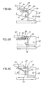
- FIGS. 8A, 8B, 8C are enlarged side elevations of the change-over piece 10 and the engaging hook 40.
- the push plate 41 of the lock slide 4 comes into contact with the upper plate 11 of the change-over piece 10. Since the upper plate 11 has high rigidity than the engaging hook 40 provided with the push plate 41, the hook 40 is biased upward, whereas the hook 40 is prevented from deflecting and deforming upward by contact with the lug 23. Accordingly, the holder 2 lowers with the lock slide 4 conversely deflecting the change-over piece 10 for deformation.
- the engaging hook 40 moves past the upper plate 11, permitting the upper plate 11 to elastically restore itself (see FIG. 8B).
- the pickup 72 moves for the playback of the disk 6.
- the head lever 7 is lowered into contact with the disk 6 by the lift mechanism to record signals.
- the present invention is characterized by the unloading movement of the cartridge at this time.
- the spring retainer 42 of the lock slide 4 pushes the projection 32 of the slide member 3, moving the latch 30 out of the state shown in FIG. 7A, i.e., from light engagement with the caved portion 64 of the cartridge 60.
- the slide member 3 moves toward the cartridge unloading direction, pushing the open shutter 61 as shown in FIG. 7B to push the cartridge 60 toward the unloading direction.
- the force of the tension spring 8 is utilized when the greatest force is required for stating the unloading of the cartridge 60.
- the movement of the slide member 3 is restricted by the contact of the front end of the slitted portion 33 with the pin 28.
- the amount of movement of the slide member 3 is smaller than the amount of movement of the cartridge 60 from the start of loading until the completion of loading, so that the cartridge in the above state will not be fully unloaded. Accordingly, the cartridge 60 is subsequently unloaded in the following manner.
- the opening piece 31 is pushing the shutter 61 open.
- the shutter 61 is biased toward the closing direction by the spring 66 disposed inside the cartridge 60, and the side end of the shutter 61 toward the closing direction is in contact with the opening piece 31.
- the contact of the shutter 61 with the opening piece 31 causes the force of the spring to act in the cartridge unloading direction, while the cartridge 60 is allowed to move toward the unloading direction, with the result that the cartridge 60 is unloaded from the holder 2 as seen in FIG. 6A.
- the shutter 61 is reliably closed by the spring 66 upon unloading.
- the present embodiment is characterized in that when to be unloaded, the cartridge 60 is disengaged from the slide member 3 so as to be movable in the unloading direction and is moved in the unloading direction by the spring 66 inside the cartridge 60. There is no need to provide the contact piece 50 (see FIG. 11) used conventionally for pushing the end face of the cartridge 60 to provide a simplified arrangement for unloading the cartridge 60.
- FIG. 12 shows a known cartridge 60 wherein the shutter 61 thereof is biased by a spring in the closing direction.
- This relates to so-called floppy disks.
- the shutter 61 is slidable in a direction orthogonal to the cartridge loading direction.
- the present applicant modified the cartridges 60 of FIGS. 9 and 12, contrived the cartridge 60 shown in FIG. 3 wherein the shutter 61 movable in the cartridge loading direction is biased toward the closing direction by a spring, and has provided a simplified mechanism for unloading the cartridge from the holder 2 using this cartridge 60.
- the shutter 61 is opened in the first position when the cartridge 60 is loaded into the holder 2, and the slide member 3 engages with the cartridge 60 in the second position.
- the opening piece 31 completely opens the shutter 61 approximately simultaneously with the engagement of the kickout member 5 with the holder 2, so that if the opening piece 31 and the kickout member 5 are not positioned properly relative to each other for one cause or another, it is likely that the cartridge 60 will be completely loaded before the shutter 61 is completely opened.
- the slide member 3 further advances into engagement with the cartridge 60, with the shutter 61 completely opened.
- the slide member 3 comes into engagement with the cartridge 60, with the shutter 61 reliably opened. Accordingly there is no likelihood that the cartridge 60 will be completely loaded without completely opening the shutter 61.
- the latch 30 is disengaged from the cartridge 60 by the movement of the lock slide 4 according to the present invention, whereas a plunger (not shown) may alternatively be provided on the chassis 1, as coupled to the latch 30 for selectively engaging the latch 30 with the cartridge 60 or disengaging the latch therefrom.
- the opening piece 31 opens the shutter 61.
- the latch 30 engages the cartridge 60, holding the cartridge 60 in the holder 2.
- the opening piece 31 remains in contact with the shutter 61.
- the latch 30 When the cartridge 60 is to be unloaded from the holder 2, the latch 30 is first disengaged from the cartridge 60, rendering the cartridge 60 free to move in the direction of unloading from the holder 2.
- the shutter 61 as opened in contact with the opening piece 31 is biased by the spring 66 toward the closing direction, and the cartridge 60 is moved toward the direction of unloading from the holder 2 by the biasing force of the spring.
- the biasing force of the spring 66 inside the cartridge 60 is used for unloading the cartridge 60 from the holder 2 according to the present invention.
- the arrangement for unloading the cartridge is simplified by obviating the need to provide the separate member conventionally used for kicking out the cartridge 60 in the unloading direction.
Landscapes
- Feeding And Guiding Record Carriers (AREA)
- Packaging Of Annular Or Rod-Shaped Articles, Wearing Apparel, Cassettes, Or The Like (AREA)
- Automatic Disk Changers (AREA)
Abstract
A holder 2 is pivotally supported on a chassis 1 for
supporting a cartridge 60 which is provided with a
shutter 61 biased by s spring 66 in a closing direction.
A slide member 3 mounted on the holder 2 is
reciprocatingly movable between a first position where
an opening piece 31 pushes the shutter 61 open with the
loading of the cartridge 60 into the holder 2 and a
second position where the latch 30 engages the cartridge
60 after moving from the first position toward the
cartridge loading direction. A release mechanism is
disposed between the chassis 1 and the holder 2 for
disengaging the latch 30 from the cartridge 60 when the
cartridge 60 is unloaded from the holder 2. The
cartidge 60 as disengaged and in contact with the
opening piece 31 is moved by the spring 66 in the
unloding direction.
Description
The present invention relates to recording or playback
devices for disks accommodated in cartridges, and
to a method of loading the cartridge into the device and
unloading the cartridge therefrom.
FIG. 9 is a perspective view of a cartridge 60
having a disk 6 accommodated therein [see JP-B No. 7-36261
(1995)]. The cartridge 60 is provided in one side
portion thereof with a groove 62, with a shutter 61
fitted thereover. The cartridge 60 has an upper surface
marked with an arrow 63 indicating the direction in
which the cartridge 60 is to be loaded into the recording
or playback device. With reference to FIG. 9, the
shutter 61 is held closed by a lock claw (not shown)
within the cartridge 60.
While the shutter 61 is opened, the disk 6 is partly
exposed from the cartridge 60. When the cartridge 60 is
loaded into the recording or playback device with the
arrow mark 63 directed toward the device, an opening
piece 31 provided inside the device advances into the
groove 62, releasing the lock claw from the shutter 61
to open the shutter 61.
A holder 2 for holding the cartridge 60 therein is
pivotally supported on a chassis 1 as at 25 upwardly or
downwardly movably. FIG. 10 is a side elevation showing
a conventional disk recording or playback device, and
FIGS. 11A and 11B are views in section of the device as
it is seen from the direction B. Provided on a support
plate 20 projecting outward from the holder 2 is a
kickout member 5 which is slidable along the cartridge
loading and unloading directions. The kickout member 5
has a contact piece 50 projecting therefrom into a path
of movement of the cartridge 60 and pushable by the
front end of the cartridge 60. The kickout member 5 is
biased in the cartridge unloading direction by a spring
8 extending between this member and the holder 2. The
opening piece 31 is provided inside the holder 2. In
the following description, the cartridge loading
direction will be referred to as forward.
The cartridge 60 is loaded into the holder 2 in the
state shown in FIG. 11A while pushing the kickout member
5 against the spring 8 on the member 5. The opening
piece 31 comes into contact with the front edge of the
shutter 61, opening the shutter 61 with the loading of
the cartridge 60. When the shutter 61 is completely
opened, the kickout member 5 is engaged with the holder
2 by a latch mechanism (not shown), holding the
cartridge 60 loaded in the holder as seen in FIG. 11B.
When the kickout member 5 is released from the
holder 2, the contact piece 50 pushes the cartridge 60
in the direction of unloading the cartridge from the
holder 2 by being biased by the spring 8 on the kickout
member 5.
However, if the inside lock claw is released to
inadvertently open the shutter 61 while the cartridge 60
shown in FIG. 9 is not in use, the shutter 61 is unable
to close automatically and therefore remains open.
Consequently, dust in the atmosphere is liable to adhere
to the disk 6, causing trouble to recording or playback.
In view of this problem, the present applicant
proposed a cartridge 60 wherein a torsion spring 66 is
provided between the shutter 61 and the cartridge 60 for
automatically closing the shutter 61 as shown in FIG. 3.
The applicant conceived the idea that if the cartridge
60 is unloaded with use of the biasing force of the
torsion spring 66 of the proposed cartridge 60, this
eliminates the need to provide the separate member for
kicking out the cartridge 60 from the holder 2, whereby
the cartridge unloading mechanism can be simplified.
An object of the present invention is to provide a
simplified cartridge unloading mechanism for use in
recording or playback devices adapted for use with
cartridges having a shutter biased in the closing
direction, the mechanism further being adapted to close
the shutter reliably.
The present invention provides a device which is
adapted for use with a cartridge 60 having a disk 6
accommodated therein and a shutter 61 biased in a
closing direction at all times by a spring 66 disposed
inside the cartridge and wherein a holder 2 is provided
with a latch 30 movable in a cartridge loading direction
for holding the cartridge 60 in a completely loaded
position by light engagement therewith.
The cartridge is loaded by the steps of:
The cartridge is unloaded by the steps of:
An embodiment of the invention will be described
below in detail.
FIG. 3 is a perspective view showing a cartridge 60
(not disclosed) prepared by the present applicant as a
trial. The cartridge 60 has a groove 62 in one side
portion thereof and a recessed portion 65 in its upper
surface. A shutter 61 is slidably disposed in the
recessed portion 65 and fitted over the groove 62. The
shutter 61 is biased in a closing direction by a torsion
spring 66 inside the cartridge 60. Even if
inadvertently opens, the shutter 61 is closed
automatically. A caved portion 64 is formed in the
bottom wall of the cartridge 60. A slide member 3 is
engageable in the caved portion 64 as will be described
later. While the shutter 61 is in an opened state, a
disk 6 within the cartridge 60 is partly exposed for
recording or reproducing signals.
FIG. 1 is an exploded perspective view of a disk
recording or playback device. A holder 2 is pivoted at
one end thereof to a chassis 1 provided with a pickup
72, and the cartridge 60 is inserted into the holder 2.
The pickup 72 is movable toward or away from a turntable
73. A bracket 71 is attached to the bottom face of the
pickup 72. A head lever 7 provided with a recording
head 70 at an outer end thereof is pivoted at a base end
thereof to the bracket 71. The head lever 7 is advanced
by a lift mechanism (not shown) into the holder 2
through an opening 26 formed in an upper wall of the
holder 2. The disk 6 in the cartridge 60 is accessible
by the recording head 70 for signal recording as in the
prior art.
A change-over piece 10 formed by bending a metal
plate and having a projecting upper plate 11 is provided
at one corner of the front end of the chassis 1.
A receiving plate 27 extends inward from the lower
end of side plate of the holder 2. The cartridge 60 is
supported at its bottom on the receiving plate 27. A
support plate 20 extends outward from the lower end of
one side portion of the holder 2. A slide member 3 is
slidably supported by the support plate 20.
FIG. 2 is an exploded perspective view of the holder
2 and the slide member 3. A pin 28 projecting from the
support plate 20 is fitted in a slit 33 of the slide
member 3 to render the slide member 3 movable in
cartridge loading and unloading directions. A lock
slide 4 is disposed above the slide member 3. Pins 29,
29 projecting from the upper wall of the holder 2 are
fitted in respective slits 44, 44 in the lock slide 4,
rendering the lock slide 4 movable in the cartridge
loading and unloading directions.
The slide member 3 is formed by bending a metal
plate and integrally has an opening piece 31 projecting
inward from the rear end thereof, a projection 32
extending upward from the approximate midportion of its
length, and a latch 30 positioned at the front end of
the member 3 and having an inwardly projecting forward
end. The opening piece 31 advances into the holder 2
through an aperture 21 formed in the holder 2 to come
into contact with an end face of the shutter 61.
The lock slide 4 is formed by bending a metal plate
and integrally has an engaging hook 40 extending forward
from the lengthwise midportion of side wall thereof
toward a front end, and a spring retainer 42 projecting
outward from the approximate midportion of length of its
side wall. The engaging hook 40 is elastically
deformable downward and has a slope 43 at its front end.
A push plate 41 extends outward approximately from the
base end of the latch 30. The change-over piece 10 (see
FIG. 1) has slightly higher rigidity than the engaging
hook 40.
The holder 2 has formed therein the aperture 21 for
the opening piece 31 to move in, and a hole 22
positioned forwardly of the aperture 21. The latch 30
fits into the hole 22, with the cartridge 60 completely
loaded in the holder 2. Projecting outward from the
holder above the hole 22 is a lug 23 with which the
engaging hook 40 of the lock slide 4 is engageable.
A hook 24 is provided on the holder 2 at a rear end
portion thereof. A tension spring 8 engaged with the
hook 24 and the spring retainer 42 on the lock slide 4
biases the lock slide 4 rearward. The contact of the
front edge of each slitted portion 44 with the pin 29
restrains the lock slide 4 from moving further rearward.
The lock slide 4 biases the slide member 3 rearward by
virtue of the contact of the projection 32 of the slide
member 3 with the rear side of the spring retainer 42.
The biasing force of the tension spring 8 is made
greater than the shutter biasing force of the torsion
spring 66 inside the cartridge 60.
The cartridge 60 is loaded into the holder 2 as
pivotally moved upward. Signals are recorded or
reproduced when the cartridge 60 is positioned as
opposed to the chassis 1 by the holder 2 pivotally moved
downward. For the convenience of description, the head
lever 7 will not be described below.
FIG. 4A and FIG. 4B are side elevations of the
holder 2 in a raised position, FIG. 4A showing the
holder ready for the loading of the cartridge 60, FIG.
4B showing the cartridge 60 as loaded completely. FIG.
5A and FIG. 5B are views corresponding respectively to
FIG. 4A and FIG. 4B as the holder is seen from the
direction A. As seen in FIG. 4A and FIG. 5A, the slope
43 of the engaging hook 40 is positioned to the rear of
the lug 23 before the cartridge 60 is loaded. The latch
30 is positioned in the rear of the hole 22 of the
holder 2 and is warped outward by contact with the side
wall of the holder 2. Further as shown in FIG. 5A, the
engaging hook 40 is positioned inwardly of the change-over
piece 10, which will not interfere with the
movement of the lock slide 4.
The operations of loading the cartridge, lowering
the holder, raising the holder and unloading the
cartridge will be described below as divided in this
way.
FIGS. 6A, 6B, 7A and 7B are plan views of the holder
2 in section. For the convenience of illustration, the
lock slide 4 and the tension spring 8 are not shown in
FIGS. 6A to 7B.
When the cartridge 60 is inserted into the holder 2
in the state shown in FIG. 6A, the opening piece 31 of
the slide member 3 fits into the groove 62 of the
cartridge 60 and comes into contact with the shutter 61.
Since the force of the tension spring 8 biasing the
slide member 3 rearward is greater than the force of the
torsion spring 66 of the cartridge 60, the slide member
3 remains unmoved even if the cartridge 60 is pushed as
shown in FIG. 6B. The shutter 61 is opened against the
torsion spring 66.
When the shutter 61 is completely opened, the
shutter 61 comes into contact with the rear edge of the
recessed portion 65 as seen in FIG. 7B. The latch 30
does not reach the hole 22 since the slide member 3
remains unmoved. This state will be referred to as a
first position.
The cartridge 60 is further pushed in from the first
position. Since the shutter 61 is unable to further
open, the shutter 61 pushes the opening piece 31 of he
slide member 3. The slide member 3 advances, causing
the latch 30 to fit into the hole 22 of the holder 2.
The latch 30 extending through the hole 22 lightly
engages in the caved portion 64 of the cartridge 60.
The cartridge 60 is held in a completely loaded state.
On the other hand, with the projection 32 of the
slide member 3 in contact with the spring retainer 42 of
the lock slide 4 as shown in FIGS. 2, 4A, 4B, the lock
slide 5 advances against the tension spring 8 when the
slide member 3 is pushed. The slope 43 of the engaging
hook 40 comes into contact with the lug 23 of the holder
2 from the state shown in FIG. 4A, whereby the hook 40
is deformed by deflection. Upon the slope 43 moving
past the lug 23, the hook 40 elastically restores itself
to become engaged with the lug 23 as seen in FIG. 4B.
The lock slide 4 is restrained from moving in the
cartridge unloading direction, and the cartridge 60 is
held in engagement with the latch 30. With the latch 30
fitting in the hole 22 of the holder 2, the slide member
3 will not move inadvertently in the direction in which
the cartridge is unloaded from the holder 2. This state
will be referred to as a second position.
When the lock slide 4 advances and becomes engaged
with the holder 2 as stated above, the amount of
movement of the lock slide 4 at this time is smaller
than the amount of movement of the lock slide 4 from the
start of loading of the cartridge 60 until the
completion of loading.
As shown in FIG. 5B, the push plate 41 of the lock
slide 4 is positioned over the change-over piece 10.
For recording or playback, the holder 2 is lowered
with the cartridge loaded completely. FIGS. 8A, 8B, 8C
are enlarged side elevations of the change-over piece 10
and the engaging hook 40. When the holder 2 is lowered
from the completely loaded state shown in FIG. 8A, the
push plate 41 of the lock slide 4 comes into contact
with the upper plate 11 of the change-over piece 10.
Since the upper plate 11 has high rigidity than the
engaging hook 40 provided with the push plate 41, the
hook 40 is biased upward, whereas the hook 40 is
prevented from deflecting and deforming upward by
contact with the lug 23. Accordingly, the holder 2
lowers with the lock slide 4 conversely deflecting the
change-over piece 10 for deformation. Upon completion
of descent of the holder 2, the engaging hook 40 moves
past the upper plate 11, permitting the upper plate 11
to elastically restore itself (see FIG. 8B).
With the holder 2 in the completely lowered state,
the pickup 72 (see FIG. 1) moves for the playback of the
disk 6. Alternatively, the head lever 7 is lowered into
contact with the disk 6 by the lift mechanism to record
signals.
When the user is to remove the cartridge 60 from the
holder 2 after the completion of recording or playback,
the holder 2 is pivotally moved upward. The present
invention is characterized by the unloading movement of
the cartridge at this time.
When the holder 2 is raised pivotally, the push
plate 41 of the lock slide 4 comes into contact with the
upper plate 11 of the change-over piece 10 as shown in
FIG. 8C. The upper plate 11, which has higher rigidity
than the engaging hook 40 provided with the push plate
41, deflects the hook 40 downward for deformation as
seen in FIG. 8C. The hook 40 is released from the lug
23, and the lock slide 4 is moved from the state shown
in FIG. 4B toward the cartridge unloading direction by
the tension spring 8.
The spring retainer 42 of the lock slide 4 pushes
the projection 32 of the slide member 3, moving the
latch 30 out of the state shown in FIG. 7A, i.e., from
light engagement with the caved portion 64 of the
cartridge 60. The slide member 3 moves toward the
cartridge unloading direction, pushing the open shutter
61 as shown in FIG. 7B to push the cartridge 60 toward
the unloading direction. The force of the tension
spring 8 is utilized when the greatest force is required
for stating the unloading of the cartridge 60. The
movement of the slide member 3 is restricted by the
contact of the front end of the slitted portion 33 with
the pin 28.
While the slide member 3 pushes the shutter 61 to
move the cartridge 60 as described above, the amount of
movement of the slide member 3 is smaller than the
amount of movement of the cartridge 60 from the start of
loading until the completion of loading, so that the
cartridge in the above state will not be fully unloaded.
Accordingly, the cartridge 60 is subsequently unloaded
in the following manner.
When the latch 30 is brought out of light engagement
with the caved portion 64 as shown in FIG. 7A, the
opening piece 31 is pushing the shutter 61 open.
However, the shutter 61 is biased toward the closing
direction by the spring 66 disposed inside the cartridge
60, and the side end of the shutter 61 toward the
closing direction is in contact with the opening piece
31. The contact of the shutter 61 with the opening
piece 31 causes the force of the spring to act in the
cartridge unloading direction, while the cartridge 60 is
allowed to move toward the unloading direction, with the
result that the cartridge 60 is unloaded from the holder
2 as seen in FIG. 6A. The shutter 61 is reliably closed
by the spring 66 upon unloading.
Stated more specifically, the present embodiment is
characterized in that when to be unloaded, the cartridge
60 is disengaged from the slide member 3 so as to be
movable in the unloading direction and is moved in the
unloading direction by the spring 66 inside the
cartridge 60. There is no need to provide the contact
piece 50 (see FIG. 11) used conventionally for pushing
the end face of the cartridge 60 to provide a simplified
arrangement for unloading the cartridge 60.
Incidentally, FIG. 12 shows a known cartridge 60
wherein the shutter 61 thereof is biased by a spring in
the closing direction. This relates to so-called floppy
disks. The shutter 61 is slidable in a direction
orthogonal to the cartridge loading direction.
The present applicant modified the cartridges 60 of
FIGS. 9 and 12, contrived the cartridge 60 shown in FIG.
3 wherein the shutter 61 movable in the cartridge
loading direction is biased toward the closing direction
by a spring, and has provided a simplified mechanism for
unloading the cartridge from the holder 2 using this
cartridge 60.
Further with the recording or playback device of the
present embodiment, the shutter 61 is opened in the
first position when the cartridge 60 is loaded into the
holder 2, and the slide member 3 engages with the
cartridge 60 in the second position. With the
conventional device shown in FIGS. 11, the opening piece
31 completely opens the shutter 61 approximately
simultaneously with the engagement of the kickout member
5 with the holder 2, so that if the opening piece 31 and
the kickout member 5 are not positioned properly
relative to each other for one cause or another, it is
likely that the cartridge 60 will be completely loaded
before the shutter 61 is completely opened.
With the device embodying the invention, however,
the slide member 3 further advances into engagement with
the cartridge 60, with the shutter 61 completely opened.
Thus, the slide member 3 comes into engagement with the
cartridge 60, with the shutter 61 reliably opened.
Accordingly there is no likelihood that the cartridge 60
will be completely loaded without completely opening the
shutter 61.
The latch 30 is disengaged from the cartridge 60 by
the movement of the lock slide 4 according to the
present invention, whereas a plunger (not shown) may
alternatively be provided on the chassis 1, as coupled
to the latch 30 for selectively engaging the latch 30
with the cartridge 60 or disengaging the latch
therefrom.
The movements of components of the device of the
invention will be described below.
When the cartridge 60 is inserted into the holder 2,
the opening piece 31 opens the shutter 61. When the
cartridge 60 is further inserted into the holder 2, the
latch 30 engages the cartridge 60, holding the cartridge
60 in the holder 2. The opening piece 31 remains in
contact with the shutter 61.
When the cartridge 60 is to be unloaded from the
holder 2, the latch 30 is first disengaged from the
cartridge 60, rendering the cartridge 60 free to move in
the direction of unloading from the holder 2. The
shutter 61 as opened in contact with the opening piece
31 is biased by the spring 66 toward the closing
direction, and the cartridge 60 is moved toward the
direction of unloading from the holder 2 by the biasing
force of the spring.
Thus, the biasing force of the spring 66 inside the
cartridge 60 is used for unloading the cartridge 60 from
the holder 2 according to the present invention. The
arrangement for unloading the cartridge is simplified by
obviating the need to provide the separate member
conventionally used for kicking out the cartridge 60 in
the unloading direction.
Because the shutter 61 is automatically closed by
the spring 66 when the cartridge 60 is unloaded from the
holder 2, there is no likelihood that the shutter 61
will open inadvertently.
Claims (3)
- A disk recording or playback device comprising a holder (2) provided on a chassis (1) for supporting a cartridge (60) having an openable shutter (61), and an opening piece (31) disposed at one side of a path of movement of the cartridge within the holder (2) for opening the shutter (61) when the cartridge (60) is loaded into the holder to expose a signal bearing surface of a disk (6) accommodated in the cartridge (60), the disk recording or playback device being characterized in that:the opening piece (31) is provided on a slide member (3) disposed on the holder (2) and movable in directions of loading and unloading the cartridge (60), the slide member (3) being provided with a latch (30) for engaging the cartridge (60) in a position where the cartridge (60) is completely loaded into the holder (2),the slide member (3) being reciprocatingly movable between a first position where the opening piece (31) pushes the shutter (61) open with the loading of the cartridge (60) into the holder (2) and a second position where the latch (30) engages the cartridge (60) after moving from the first position toward the cartridge loading direction,a release mechanism disposed between the chassis (1) and the holder (2) for disengaging the latch (30) from the cartridge (60) when the cartridge (60) is unloaded from the holder (2).
- A disk recording or playback device according to claim 1 wherein the holder (2) is provided on the chassis (1) upwardly and downwardly movably, and the release mechanism comprises a lock slide (4) positioned on the holder (4) and operatively connected to the slide member (3) to engage with the holder (2) with the loading of the cartridge (60) into the holder (2) in a raised position, and a change-over piece (10) positioned on the chassis (1) to permit passage of the lock slide (4) when the holder (2) is lowered and to disengage the lock slide (4) from the holder (2) when the holder (2) is raised.
- In a disk recording or playback device comprising a holder (2) to be loaded with a cartridge (60) having an openable shutter (61), and an opening piece (31) projecting laterally of a path of movement of the cartridge (60) for moving the shutter (61) with loading of the cartridge (60) into the holder (2) to expose a signal bearing surface of a disk (6) accommodated in the cartridge (60), a cartridge loading and unloading method for the signal recording or playback device characterized in that:the shutter (61) is biased in a closing direction at all times by a spring (66) disposed inside the cartridge (60), a latch (60) being provided on the holder (2) and movable in a cartridge loading direcction for engaging the cartridge (60) in a position where the carbridge is completely loaded,the cartridge (60) being loadable into the holder (2) by the steps of:inserting the cartridge (60) into the holder (2) and causing an opening piece (31) to open the shutter (61) against the force of the spring (66),further inserting the cartridge (60) into the holder (2) along with the opening piece (31) with the shutter (61) completely opened, andholding the cartridge (60) in the holder (2) by causing the latch (30) to engage the cartridge (60),the cartridge (60) being unloadable from the holder (2) by the steps of:disengaging the latch (30) from the cartridge (60), andcausing the force of the spring (66) to move the shutter (61) as completely opened in contact with the opening piece (31) in a direction of unloading the cartridge (60) from the holder (2) and closing the shutter (61) by the force of the spring (66).
Applications Claiming Priority (3)
| Application Number | Priority Date | Filing Date | Title |
|---|---|---|---|
| JP7477099 | 1999-03-19 | ||
| JP7477099 | 1999-03-19 | ||
| PCT/JP2000/001723 WO2000057415A1 (en) | 1999-03-19 | 2000-03-21 | Device for recording or reproducing signals on disk and method of inserting and extracting cartridge for the device |
Publications (2)
| Publication Number | Publication Date |
|---|---|
| EP1178481A1 true EP1178481A1 (en) | 2002-02-06 |
| EP1178481A4 EP1178481A4 (en) | 2004-09-08 |
Family
ID=13556866
Family Applications (1)
| Application Number | Title | Priority Date | Filing Date |
|---|---|---|---|
| EP00909777A Withdrawn EP1178481A4 (en) | 1999-03-19 | 2000-03-21 | Device for recording or reproducing signals on disk and method of inserting and extracting cartridge for the device |
Country Status (5)
| Country | Link |
|---|---|
| US (1) | US6802069B1 (en) |
| EP (1) | EP1178481A4 (en) |
| KR (1) | KR20010113763A (en) |
| CN (1) | CN1145948C (en) |
| WO (1) | WO2000057415A1 (en) |
Families Citing this family (5)
| Publication number | Priority date | Publication date | Assignee | Title |
|---|---|---|---|---|
| JP4168971B2 (en) * | 2004-05-10 | 2008-10-22 | ソニー株式会社 | Disc recording and / or playback device |
| JP4280867B2 (en) * | 2004-05-10 | 2009-06-17 | ソニー株式会社 | Disc recording and / or playback device |
| US7685057B2 (en) * | 2006-04-12 | 2010-03-23 | Uat, Inc. | System and method for facilitating unified trading and control for a sponsoring organization's money management process |
| CN102591429A (en) * | 2011-01-18 | 2012-07-18 | 鸿富锦精密工业(深圳)有限公司 | Locking fastener component and electronic device using same |
| US11020525B2 (en) | 2017-08-10 | 2021-06-01 | West Pharma. Services IL, Ltd. | Injector cartridge door locking mechanism |
Family Cites Families (9)
| Publication number | Priority date | Publication date | Assignee | Title |
|---|---|---|---|---|
| DE3415412A1 (en) * | 1983-04-25 | 1984-12-20 | Canon K.K., Tokio/Tokyo | Recording or reproducing device |
| DE69319660T2 (en) * | 1992-05-22 | 1998-11-19 | Sony Corp | Disk cassette charger |
| JP3127579B2 (en) | 1992-05-29 | 2001-01-29 | ソニー株式会社 | Disk cartridge attachment / detachment device |
| US5590109A (en) * | 1993-09-17 | 1996-12-31 | Matsushita Electric Industrial Co. | Disc apparatus |
| JP3533681B2 (en) | 1993-09-20 | 2004-05-31 | ソニー株式会社 | Eject mechanism for cartridge |
| US5650891A (en) * | 1994-10-18 | 1997-07-22 | Iomega Corporation | Apparatus for performing multiple functions in a data storage device using a single electro-mechanical device |
| JP3425336B2 (en) * | 1997-09-29 | 2003-07-14 | 松下電器産業株式会社 | Disk unit |
| JP3425338B2 (en) * | 1997-10-03 | 2003-07-14 | 松下電器産業株式会社 | Disk unit |
| JP3658516B2 (en) * | 1998-03-16 | 2005-06-08 | 日立マクセル株式会社 | Cartridge for recording medium |
-
2000
- 2000-03-21 KR KR1020017011847A patent/KR20010113763A/en not_active Ceased
- 2000-03-21 WO PCT/JP2000/001723 patent/WO2000057415A1/en not_active Ceased
- 2000-03-21 US US09/926,159 patent/US6802069B1/en not_active Expired - Fee Related
- 2000-03-21 EP EP00909777A patent/EP1178481A4/en not_active Withdrawn
- 2000-03-21 CN CNB008052166A patent/CN1145948C/en not_active Expired - Fee Related
Also Published As
| Publication number | Publication date |
|---|---|
| EP1178481A4 (en) | 2004-09-08 |
| KR20010113763A (en) | 2001-12-28 |
| US6802069B1 (en) | 2004-10-05 |
| CN1344408A (en) | 2002-04-10 |
| CN1145948C (en) | 2004-04-14 |
| WO2000057415A1 (en) | 2000-09-28 |
Similar Documents
| Publication | Publication Date | Title |
|---|---|---|
| US6802069B1 (en) | Device for recording or reproducing signals on disk and method of inserting and extracting cartridge for the device | |
| JPS61292261A (en) | Cartridge handler | |
| US6542329B2 (en) | Holder mounting structure | |
| EP1227488B1 (en) | Cartridge containing disk and device for recording or reproducing signal on or from the disk | |
| US6807669B2 (en) | Device for accommodating cartridge storage device and disk recording or playback apparatus | |
| EP0404589B1 (en) | Disc drive apparatus | |
| US6829773B1 (en) | Device for recording or reproducing signal on or from disk with a releasing mechanism | |
| JP3427006B2 (en) | Apparatus for recording or reproducing signals on disk and method for inserting and ejecting cartridges from the apparatus | |
| JPH0145148B2 (en) | ||
| EP0992991B1 (en) | Recording or playback device for disk contained in cartridge | |
| JP2000040331A (en) | Disk case | |
| JP3127579B2 (en) | Disk cartridge attachment / detachment device | |
| JP3409430B2 (en) | Optical disk drive | |
| JP2643727B2 (en) | Disk cartridge mounting device | |
| JP2000207804A (en) | Disk unit | |
| JP3731386B2 (en) | Recording medium loading device | |
| JP2003178508A (en) | Optical disk drive | |
| JP2002237120A (en) | Disk recording and playback device | |
| JPH0343704B2 (en) | ||
| JPH0473227B2 (en) | ||
| JPH0944949A (en) | Cassette recorder cassette loading device | |
| JPH0626075B2 (en) | Locking device for magnetic recording medium in magnetic recording / reproducing device | |
| JP2003045141A (en) | Disc case | |
| JPH05114273A (en) | Cassette shutter opening mechanism | |
| JPH07302459A (en) | Disk device |
Legal Events
| Date | Code | Title | Description |
|---|---|---|---|
| PUAI | Public reference made under article 153(3) epc to a published international application that has entered the european phase |
Free format text: ORIGINAL CODE: 0009012 |
|
| 17P | Request for examination filed |
Effective date: 20011018 |
|
| AK | Designated contracting states |
Kind code of ref document: A1 Designated state(s): AT BE CH CY DE DK ES FI FR GB GR IE IT LI LU MC NL PT SE |
|
| RBV | Designated contracting states (corrected) |
Designated state(s): DE FR GB |
|
| A4 | Supplementary search report drawn up and despatched |
Effective date: 20040728 |
|
| 17Q | First examination report despatched |
Effective date: 20050414 |
|
| STAA | Information on the status of an ep patent application or granted ep patent |
Free format text: STATUS: THE APPLICATION HAS BEEN WITHDRAWN |
|
| 18W | Application withdrawn |
Effective date: 20060313 |