EP1178436A2 - Image measurement method, image measurement apparatus and image measurement program storage medium - Google Patents
Image measurement method, image measurement apparatus and image measurement program storage medium Download PDFInfo
- Publication number
- EP1178436A2 EP1178436A2 EP01120401A EP01120401A EP1178436A2 EP 1178436 A2 EP1178436 A2 EP 1178436A2 EP 01120401 A EP01120401 A EP 01120401A EP 01120401 A EP01120401 A EP 01120401A EP 1178436 A2 EP1178436 A2 EP 1178436A2
- Authority
- EP
- European Patent Office
- Prior art keywords
- measuring
- point
- voting
- coordinates
- parameter
- Prior art date
- Legal status (The legal status is an assumption and is not a legal conclusion. Google has not performed a legal analysis and makes no representation as to the accuracy of the status listed.)
- Withdrawn
Links
Images














Classifications
-
- G—PHYSICS
- G06—COMPUTING OR CALCULATING; COUNTING
- G06T—IMAGE DATA PROCESSING OR GENERATION, IN GENERAL
- G06T7/00—Image analysis
- G06T7/20—Analysis of motion
- G06T7/269—Analysis of motion using gradient-based methods
-
- G—PHYSICS
- G06—COMPUTING OR CALCULATING; COUNTING
- G06T—IMAGE DATA PROCESSING OR GENERATION, IN GENERAL
- G06T7/00—Image analysis
- G06T7/20—Analysis of motion
- G06T7/246—Analysis of motion using feature-based methods, e.g. the tracking of corners or segments
-
- G—PHYSICS
- G06—COMPUTING OR CALCULATING; COUNTING
- G06T—IMAGE DATA PROCESSING OR GENERATION, IN GENERAL
- G06T7/00—Image analysis
- G06T7/50—Depth or shape recovery
- G06T7/55—Depth or shape recovery from multiple images
- G06T7/593—Depth or shape recovery from multiple images from stereo images
Definitions
- the present invention relates to an image measurement method of measuring positions and azimuths of a point and a surface, which appear on an image, in space, an image measurement apparatus for implementing the measurement method, and an image measurement program storage medium storing an image measurement program for implementing the image measurement.
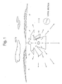
- Fig. 1 shows an optical flow pattern which is reflected in the retinas of a pilot.
- the pilot exactly lands an airplane in accordance with this pattern through perceiving a slope (three-dimensional azimuth) of a runway and information as to such a matter that "continuous traveling of the airplane brings about an arrival at the runway after what second". That is, the pilot measures a three-dimensional azimuth of a plane (the runway) and a "time up to crossing the plane" to land the airplane.
- the person can exactly avoid the wall and walk even if it is a curved passage. Also in the event that a person walks in an office, in a similar fashion, the person can avoid an "object constituted of a plane", such as a white board, a desk, a locker. Further, in the event that a person drives a motor car, the person performs driving on a high way, putting a car into the garage, and the like through performing the similar "three-dimensional measurement on a plane".
- our visual sensation makes it possible to perform an exact movement through a measurement of three-dimensional geometric information (a three-dimensional azimuth on a plane, and a time up to crossing the plane) of an object constituting of a plane (there are a lot of such objects). Also with respect to a curved object, it is possible to spatially recognize the curved object through a measurement of three-dimensional geometric information of a "group of planes contacting to the curved object".
- a measuring of the three-dimensional geometric information includes a measurement of the shortest distance to a plane.
- a first image measurement method comprising :
- the present invention provides, of image measurement methods, a second image measurement method comprising:
- the present invention provides, of image measurement methods, a third image measurement method comprising:
- a fourth image measurement method comprising:
- a fifth image measurement method comprising:
- the present invention provides, of image measurement methods, a sixth image measurement method comprising:
- a seventh image measurement method comprising : :
- an eighth image measurement method comprising:
- a ninth image measurement method comprising:
- said image measurement method further comprises a third step of determining an azimuth of a measuring plane including a plurality of measuring points joining a voting for a maximal point and/or a physical quantity indexing a superposing time in which the measuring plane is superposed on the observation point in such a manner that a maximal point wherein a value by said voting in the voting space offers a maximal value is determined.
- the present invention provides, of image measurement methods, a tenth image measurement method comprising : :
- said image measurement method further comprises a fourth step of determining a true moving direction relative to the observation point on the measuring point, and of determining an azimuth of a measuring plane including a plurality of measuring points joining a voting for a maximal point determined on a voting space associated with the true moving direction, and/or a physical quantity indexing a superposing time in which the measuring plane is superposed on the observation point, in such a manner that a maximal point wherein a value by a voting is determined on each voting space, and the voting space associated with the true moving direction is selected in accordance with information as to the maximal value on the maximal point.
- the present invention provides, of image measurement methods, a eleventh image measurement method comprising :
- said image measurement method further comprises a third step of determining an azimuth of a measuring plane including a plurality of measuring points joining a voting for a maximal point and/or a physical quantity indexing a shortest distance from the observation point to the measuring plane at one measuring time of the two measuring times in such a manner that a maximal point wherein a value by said voting offers a maximal value is determined in the voting space.
- the present invention provides, of image measurement methods, a twelfth image measurement method comprising:
- said image measurement method further comprises a fourth step of determining a true moving direction, and of determining an azimuth of a measuring plane including a plurality of measuring points joining a voting for a maximal point determined on a voting space associated with the true moving direction, and/or a shortest distance from the observation point to the measuring plane at one measuring time of the two measuring times, in such a manner that a maximal point wherein a value by said voting offers a maximal value is determined on each voting space, and a voting space associated with the true moving direction relative to the observation point on the measuring point is selected in accordance with information as to the maximal value on the maximal point.
- An image measuring method of the present invention may be defined by alternative expressions as set forth below.
- a first image measurement apparatus comprising :
- the present invention provides, of image measurement apparatuses, a second image measurement apparatus comprising :
- the present invention provides, of image measurement apparatuses, a third image measurement apparatus comprising :
- a fourth image measurement apparatus comprising:
- a fifth image measurement apparatus comprising :
- the present invention provides, of image measurement apparatuses, a sixth image measurement apparatus comprising :
- a seventh image measurement apparatus comprising:
- an eighth image measurement apparatus comprising :
- a ninth image measurement apparatus comprising :
- said image measurement apparatus further comprises a detection unit for determining an azimuth of a measuring plane including a plurality of measuring points joining a voting for a maximal point and/or a physical quantity indexing a superposing time in which the measuring plane is superposed on the observation point in such a manner that a maximal point wherein a value by said voting in the voting space offers a maximal value is determined.
- the present invention provides, of image measurement apparatuses, a tenth image measurement apparatus comprising :
- said image measurement apparatus further comprises a detection unit of determining a true moving direction relative to the observation point on the measuring point, and of determining an azimuth of a measuring plane including a plurality of measuring points joining a voting for a maximal point determined on a voting space associated with the true moving direction, and/or a physical quantity indexing a superposing time in which the measuring plane is superposed on the observation point, in such a manner that a maximal point wherein a value by a voting is determined on each voting space, and the voting space associated with the true moving direction is selected in accordance with information as to the maximal value on the maximal point.
- an eleventh image measurement apparatus comprising:
- said measurement apparatus further comprises a detection unit for determining an azimuth of a measuring plane including a plurality of measuring points joining a voting for a maximal point and/or a physical quantity indexing a shortest distance from the observation point to the measuring plane at one measuring time of the two measuring times in such a manner that a maximal point wherein a value by said voting offers a maximal value is determined in the voting space.
- the present invention provides, of image measurement apparatuses, a twelfth image measurement apparatus comprising :
- said image measurement apparatus further comprises a detection unit for determining a true moving direction, and determining an azimuth of a measuring plane including a plurality of measuring points joining a voting for a maximal point determined on a voting space associated with the true moving direction, and/or a shortest distance from the observation point to the measuring plane at one measuring time of the two measuring times, in such a manner that a maximal point wherein a value by said voting offers a maximal value is determined on each voting space, and a voting space associated with the true moving direction relative to the observation point on the measuring point is selected in accordance with information as to the maximal value on the maximal point.
- the present invention provides, of image measurement program storage media, a first image measurement program storage medium storing an image measurement program comprising:
- the present invention provides, of image measurement program storage media, a second image measurement program storage medium storing an image measurement program comprising:
- the present invention provides, of image measurement program storage media, a third image measurement program storage medium storing an image measurement program comprising:
- a fourth image measurement program storage medium storing an image measurement program comprising:
- the present invention provides, of image measurement program storage media, a fifth image measurement program storage medium storing an image measurement program comprising:
- the present invention provides, of image measurement program storage media, a sixth image measurement program storage medium storing an image measurement program comprising:
- a seventh image measurement program storage medium storing an image measurement program comprising:
- an eighth image measurement program storage medium storing an image measurement program comprising:
- a ninth image measurement program storage medium storing an image measurement program comprising:
- said image measurement program further comprises a third step of determining an azimuth of a measuring plane including a plurality of measuring points joining a voting for a maximal point and/or a physical quantity indexing a superposing time in which the measuring plane is superposed on the observation point in such a manner that a maximal point wherein a value by said voting in the voting space offers a maximal value is determined.
- the present invention provides, of image measurement program storage media, a tenth image measurement program storage medium storing an image measurement program comprising:
- said image measurement program further comprises a fourth step of determining a true moving direction relative to the observation point on the measuring point, and of determining an azimuth of a measuring plane including a plurality of measuring points joining a voting for a maximal point determined on a voting space associated with the true moving direction, and/or a physical quantity indexing a superposing time in which the measuring plane is superposed on the observation point, in such a manner that a maximal point wherein a value by a voting is determined on each voting space, and the voting space associated with the true moving direction is selected in accordance with information as to the maximal value on the maximal point.
- an eleventh image measurement program storage medium storing an image measurement program comprising:
- said image measurement program further comprises a third step of determining an azimuth of a measuring plane including a plurality of measuring points joining a voting for a maximal point and/or a physical quantity indexing a shortest distance from the observation point to the measuring plane at one measuring time of the two measuring times in such a manner that a maximal point wherein a value by said voting offers a maximal value is determined in the voting space.
- the present invention provides, of image measurement program storage media, a twelfth image measurement program storage medium storing an image measurement program comprising:
- said image measurement program further comprises a fourth step of determining a true moving direction, and of determining an azimuth of a measuring plane including a plurality of measuring points joining a voting for a maximal point determined on a voting space associated with the true moving direction, and/or a shortest distance from the observation point to the measuring plane at one measuring time of the two measuring times, in such a manner that a maximal point wherein a value by said voting offers a maximal value is determined on each voting space, and a voting space associated with the true moving direction relative to the observation point on the measuring point is selected in accordance with information as to the maximal value on the maximal point.
- Fig. 2 is a perspective illustration of a computer system which is adopted as one embodiment of an image measurement apparatus of the present invention.
- a computer system 300 comprises a main frame 301 incorporating thereinto a CPU, a RAM memory, a magnetic disk, a communication board, an image input board, etc., a CRT display 302 for performing an image display in accordance with an instruction from the main frame 301, a keyboard 303 for inputting a user's instruction and character information into the computer, and a mouse 304 for designating an arbitrary position on a display screen of the CRT display 302 to input an instruction according to an icon displayed on the position.
- the main frame 301 has on appearances a floppy disk loading slot 301a and an MO (magneto-optic disk) loading slot 301b onto which a floppy disk and an MO (magneto-optic disk) are detachably loaded, respectively. And the main frame 301 also incorporates thereinto a floppy disk driver for driving the loaded floppy disk and an MO (magneto-optic disk) driver for driving the loaded MO.
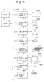
- Fig. 3 is a block diagram of the computer system shown in Fig. 2.
- the computer system shown in Fig. 3 comprises a central processing unit (CPU) 311, a RAM 312, a magnetic disk controller 313, a floppy disk driver 314, an MO (magneto-optic disk) driver 315, a mouse controller 316, a keyboard controller 317, a display controller 318, a communication board 319, and an image input board 320.
- CPU central processing unit
- RAM random access memory
- magnetic disk controller disk controller
- a floppy disk driver 314 a magnetic disk controller
- MO magnetic-optic disk driver
- the magnetic disk controller 313 serves to access a magnetic disk 321 incorporated into the main frame 301 (cf. Fig. 2).
- the floppy disk driver 314 and the MO driver 315 onto which a floppy disk 322 and an MO (magneto-optic disk) 323 are detachably loaded, respectively, serve to access the floppy disk 322 and the MO 323, respectively.
- the mouse controller 316 and the keyboard controller 317 serve to transmit operations of the mouse 304 and the keyboard 303 into the computer.
- the display controller 318 causes the CRT display 302 to display an image in accordance with a program operative in the CPU 311.
- the communication board 319 is connected through a communication line 400 to a communication network such as a LAN and an internet, and serves to receive image data via the communication network for instance.
- a communication network such as a LAN and an internet
- the image input board 320 is connected to an external camera 11 (e.g. an electronic still camera, or a video camera), and serves to take in image data obtained through a photography by the camera 11 inside the computer. While Fig. 3 shows only one camera, it is acceptable that two cameras are connected to the image input board 320, so that two sheets of image, which are obtained through a simultaneous photography for the same subject by the two cameras from mutually different directions corresponding to human's binocular parallax for example, can be entered.
- an external camera 11 e.g. an electronic still camera, or a video camera
- an embodiment of an image measurement apparatus according to the present invention is implemented in the form of a combination of a hardware of the computer system shown in Figs. 2 and 3 and a program installed in the computer system and to be executed.
- a program, which causes the computer system to be operative as an image measurement apparatus according to the present invention corresponds to an image measurement program referred to in the present invention.
- the floppy disk 322 and the MO 323, which store the image measurement program correspond to an image measurement program storage medium referred to in the present invention.
- the installed image measurement program is stored in the magnetic disk 321.
- the magnetic disk 321, which stores the image measurement program also corresponds to an image measurement program storage medium referred to in the present invention.
- a measurement method of a three-dimensional azimuth of a plane and a time up to crossing 1.
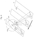
- Fig. 4 shows a state that a plane wherein a normal vector is given by n s (a plane wherein a three-dimensional azimuth is given by n s ) is moved from the present time t 0 to the subsequent time t 1 , and the plane goes across a camera center O at time t c .
- the tops (white circles) of a triangle on the plane at the respective times are projected on a retina of an eyeball (or a spherical camera) in the form of cross points (black circles) between lines coupling the camera center O with the respective tops and a surface of the eyeball (or a spherical camera).
- the diameter of the eyeball (or a spherical camera) is given by 1. Consequently, the vector coupling the camera center O with the black circle offers a "unit vector" of magnitude 1.
- Fig. 5 is an explanatory view useful for understanding a principle of measuring a three-dimensional azimuth of a plane.
- Fig. 5 shows a state at time t c .
- the plane passes through the camera center O.
- a dot group (white circles) on a plane is projected on a sphere in the form of a "dot group (black circles) on a large circle g ns " through a degeneration.
- This large circle is a line of intersection of the plane with the sphere. Consequently, the vector p c perpendicularly intersects with the normal vector n s of the plane.
- the normal vector n s of the plane can be measured in the form of a "polar transformation" of the vector p c as follows. That is, when a large circle (the largest circle on the sphere) is drawn on each of the vectors p c taking it as a center, a group of large circles intersect at one point so that a normal vector (that is, a three-dimensional azimuth) n s of the plane is measured in the form of the cross point. In this manner, a determination of p c on a plurality of points makes it possible to determine a three-dimensional azimuth of the plane through the polar transformation.
- the term of the polar transformation will be explained.
- the points p c and the large circles on the sphere are referred to as “poles” and “polar lines”, respectively, and an operation of transferring the pole p c to the polar line (large circle) is referred to as the "polar transformation” or a "duality”.
- the normalized time is defined as a time wherein time t c up to crossing a plane is normalized with a time difference ⁇ t between the present time t 0 and the subsequent time t 1 , and is expressed by the following equation (1).
- Fig. 6 is a view showing a state that a triangle (black circles), which is projected on a sphere shown in Fig. 4, is moved.
- a triangle 1 p 0 , 2 p 0 , 3 p 0 at the present time t 0 is moved to 1 p 1 , 2 p 1 , 3 p 1 at the subsequent time t 1 , and is moved, at the time t c crossing a plane, to three points 1 p c , 2 p c , 3 p c on the "large circle g ns perpendicularly intersecting with the normal vector ns of a plane" through a degeneration, and finally converges in a moving direction v after the infinite time elapses.
- the three tops are moved on "large circles 1 g, 2 g, 3 g coupling those with the moving direction v", respectively. It is noted that the moving direction v is involved in a position after the infinite time elapses and thus is also denoted by P inf hereinafter.
- Fig. 7 is an explanatory view useful for understanding a principle of measuring a distance up to a point.
- a position P 0 at the present time, a position P 1 at the subsequent time, and a position P inf after the infinite time elapses are determined so that a three-dimensional distance d 0 of a point at the present time (or a distance from the camera center O to the point P 0 ) can be measured.
- Fig. 7 shows a sectional view wherein a sphere is cut at "one (g) of the large circles each representative of a moving locus" shown in Fig. 6.
- d 0 ⁇ x sin (p inf p 1 )/sin p 0 p 1 )
- a "simple ratio (a b c) as to three points a, b, c of the large circle is defined (cf. "Projective Geometry (by Gurevic, G.B., Tokyo Books)", page 6) as follows.
- the adoption of the expression of the simple ratio may avoid the necessity of the adoption of the scheme of the central projection, and thus makes it possible to measure the distance d 0 from not only the above-mentioned three points p 0 , p 1 , p c moving on the large circle of a "spherical camera or an eyeball", but also three points p 0 , p 1 , p c moving on a "straight line of an image on a planar camera". That is, it is possible to measure the distance d 0 of a point on a three-dimensional basis regardless of a camera system for a photography of an image.
- d 0 ⁇ x (p inf p 0 p 1 )
- Fig. 8 is an explanatory view useful for understanding a principle of measuring a normalized time.
- Fig. 8 is equivalent to a figure in which a "plane crossing the camera center O at the time t c " is added into Fig. 7.
- V a moving velocity
- a relation between the "moving distance ⁇ x from the present time to the subsequent time” and the time difference ⁇ t between the present time and the subsequent time is expressed by the following equation (7).
- equation (7) is substituted for the equation (4) and the equation (6), the following equations (8a) and (8b) can be obtained.
- the normalized time n t c up to going across the plane can be determined in accordance with the following equations (10a) and (10b).
- the compound ratio ⁇ a b c d ⁇ as to four points a, b, c, d on the large circle is defined by the following equation (11a) in the form of the "ratio of two simple ratios (a b c) and (a b d)", and is expressed by the relation set forth in the following equation (11b) (cf. "Projective Geometry (by Gurevic, G.B., Tokyo Books)", pages 257 and 119).
- Equation (12a) means on a projective geometric basis "the normalized time n t c is coordinates of p c which is measured by a basic point system wherein the original point, the infinite-point and the unit point are given by p 0 , p inf , p 1 , respectively. (12b)
- the compound ratio of the equation (12a) is the basic invariant of the projective geometry, and is constant for the arbitrary projection and cut. That is, the compound ratio is constant for an "image on an arbitrary camera system" of a spherical camera, a planar camera and the like.
- the position p 0 at the present time and the position p 1 at the subsequent time can be known from an image on a camera.
- the position at the infinite time can be known since it is equivalent to a moving direction v of the plane (or the camera).
- the position p c at the time t c wherein the plane goes across the camera center is the position p c at the time t c wherein the plane goes across the camera center.
- the position p c can be estimated by the "compound ratio transformation” which is obtained through a modification of the equation (10a) or the equation (12a).
- the three-dimensional geometric information (a three-dimensional azimuth n s0 and a normalized time n t c0 up to crossing) of a plane can be measured through the "polar transformation" of p c in accordance with the method of 1.1.
- the normalized time n t c and positions p 0 , p 1 , p inf at three times are determined, and "the above-mentioned position p c ", which is important for determination of the three-dimensional geometric information, is computed. Since four variables n t c , p 0 , p 1 , p inf can be determined in the equation (12a), it is possible to determine the remaining variable p c . This computation is well known as a method of computation for a compound ratio of a projective geometry.
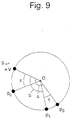
- FIG. 9 shows a sectional portion of the sphere extracted from Fig. 8.
- the positions of p 0 , p 1 , p c are represented by the central angles a, b, x taking p inf as the basic point (it is acceptable that the basic point may be an arbitrary position).
- the various central angles are as follows.
- p inf p c x p 0
- the position p c is one in which the position at the arbitrarily time n t c ⁇ t is "predicted". This prediction is apparent from the derivation process of the equation (10a) which is the base for the compound ratio transformation.
- the equation (12b) may be understood as follows:
- the time, in which the positions p c thus predicted are located on the large circles, corresponds to the "time n t c0 ⁇ t in which a plane crosses the camera center (that is, the time t c0 )", and the "normalized time n t c0 up to crossing a plane” is determined in accordance with that time.
- step (1) 60 Utility Nuclear Electric Power Generation Institution Robot Development Contract Research (Advanced Robot Technology Research Association)".
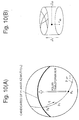
- the circles are accumulated taking the normalized time parameter n t c as a vertical axis to form the "cylindrical arrangement" as shown in Fig. 10(B).
- This feature makes the geometric meaning of the step (1) clear. That is, it means that the "normalized time parameter n t c " arbitrarily given by the step (1) designates height coordinates of this cylinder, and in the steps (2) and (3) the sectional circle at that height, or one in which a spherical image shown in Fig. 10(A) is transformed inside the "circle", is drawn.
- the parameter n t c is arbitrarily given, and thus, as seen from Fig.
- input data There is a vertical plane right in front of a spherical camera (or an eyeball), and a distance up to the camera center is 3m.
- the plane moves in a direction vertical to the plane (that is, a direction parallel with the normal vector n s0 of the plane) toward the camera at the velocity 1m/second.
- the "positions p 0 , p 1 on the sphere at the present time and the subsequent time” are observed in the form of input image data.
- a time difference ⁇ t between the present time and the subsequent time is 0.05 second.
- the position p inf at the infinite time is equivalent to a moving direction v and is located at the center of the visual field.
- the normal vector n s0 of the plane is located at the center of the visual field.
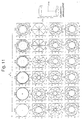
- Fig. 11 is an illustration showing a result of a computer simulation in which three-dimensional geometric information of a plane ( n t c0 and n s0 ) is determined from the positions p 0 , p 1 at the present time and the subsequent time and the position p inf after the infinite time elapses in accordance with the above-mentioned algorithm (the compound ratio transformation and the polar transformation).
- Fig. 11 there are shown the "sectional circles of cylinders" at the respective normalized time parameters n t c explained in connection with 1. 3. 3.
- Each of the sectional circles is obtained through a projection of the sphere of Fig. 10(A) onto a plane passing through the sphere in accordance with the "equidistant projection (cf.
- the normalized distance n d c is one in which the "distance d c up to going across a plane in a moving direction" (this distance is Vt c in Fig. 8) is normalized with the "moving distance ⁇ x from the present time to the subsequent time".
- the normalized distance n d c is expressed by the following equation.
- the equation (7) is substituted for the equation (17a), and the equation (17a) is modified.
- the normalized distance n d c is equivalent to the above-mentioned "normalized time n t c ". Therefore, it is possible to measure the normalized distance n d c using the method (1. 3. 2) of determining the normalized time n t c as it is.
- a method capable of measuring "the three-dimensional azimuth n s and the normalized time n t c " even if the moving direction v is unknown According to this method, even if the moving direction on photography as to an image of an internet, a video, a movie, etc., for instance, is unknown, it is possible to measure the "azimuth and time". Further, in the event that a plane moves, generally, the moving direction is unknown. However, even in such a case, it is possible to measure the "azimuth and time" together with the moving direction v. The outline of the method will be described hereinafter.
- the normalization shortest distance is one in which the shortest distance d s up to a plane is normalized with the "moving distance ⁇ x of a camera (or a plane) from the present time to the subsequent time".
- n d s n t c (n s ⁇ v)
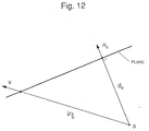
- Fig. 12 shows a section of a plane wherein a vector n s of the plane and a moving direction v lie).
- the "shortest distance d s up to a plane from the camera center O" is a normal direction component of the "distance Vt c up to going across a plane in the moving direction”. Consequently, the following equation consists.
- d s Vt c (n s ⁇ v) where V denotes a magnitude of a moving velocity
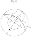
- the curved line drawn in the step (5) of 2. 1 is a small circle, and then there will be explained a method of measuring a normalization shortest distance n d s0 up to a plane and a three-dimensional azimuth n s0 of a plane.
- Fig. 14 shows, for the purpose of proof, one in which various parameters are drawn in Fig. 13.
- the steps (3) to (5) of 2. 1 are expressed with following mathematical expression using those parameters, and it will be shown that the curved line of the step (5) of 2. 1 is a small circle.
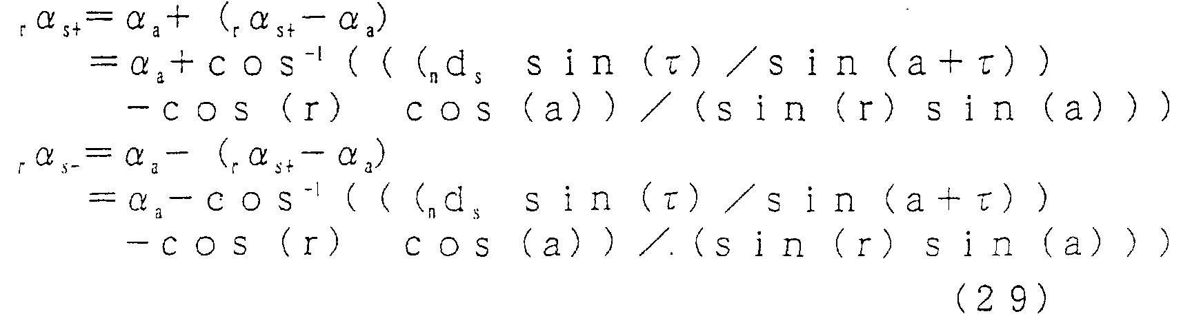
- longitudinal coordinates r of the azimuth candidates points r n s+ , r n s- of a plane are expressed in the form of the "radius r of the small circle of the step (2)", and the longitudinal coordinates points r ⁇ s+ , r ⁇ s- are expressed by the equation (29).
- the curved line consisting of two cross points r n s+ , r n s- shown in Fig. 14 is the "small circle of the radius R taking p 0 as its center”. This implies that it is possible to transfer an arbitrary point p 0 to the small circle. This transformation is referred to as a "small circle transformation”.
- the equation (31) may be expressed with a position P 0 at the present time, a position P 1 at the subsequent time, and a position P inf after the infinite time elapses.
- ⁇ and a + ⁇ are expressed by the central angle of the equation (15), the equation (31) is given by the following equation.
- R cos -1 ( n d s sin (p 0 p 1 ) / s i n (p inf p 1 ))
- the equation (31) expresses the radius R using motion parallax ⁇ . However, in the event that the position p 1 at the subsequent time is known, the radius R is given by the following equation through substituting the equation (13) for the equation (32).
- R cos -1 ( n d s sin (b-a) / sin (b))
- the radius R determined by the equation (34b) indicates a necessary condition for the existence of a plane passing the "point P 0 located at the distance d 0 from the camera center O" wherein the shortest distance is given by d s . That is, the radius R determined by the equation (34b) indicates that the azimuth n s has to be inclined from the direction P 0 of the point by the "angle R determined by the equation (34b)" for existence of the plane.
- the equation (34b) can be expressed in the form of the equation (35) using the "normalization shortest distance n d s of a plane” and the "normalization shortest distance n d 0 of a point" defined by the equation (36).
- R cos -1 ( n d s / n d 0 )
- n d 0 d 0 / ⁇ x
- equation (34b) can be also expressed in the form of the following equation (37) through substituting the equation (6) for the equation (34a).
- R cos -1 ( n d s / (p inf p 0 p 1 ))
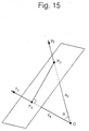
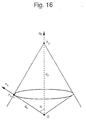
- the small circle transformation on the sphere in 2. 2. 1 is equivalent to the subsequent transformation in the three-dimensional space. In other words, it is equivalent to the transformation of the "point P 0 in the space (direction p 0 , distance d 0 )" to the circumference of the right circular cone shown in Fig. 16, that is, the normal vector group ⁇ n s ⁇ of the "whole plane passing through P 0 wherein the shortest distance from the camera center O is given by d s ". This is the geometric meaning of the small circle transformation.
- the normalization shortest distance parameter n d s arbitrarily given by the step (1) designates height coordinates of this cylinder, and in the steps (2) and (3) the sectional circle at that height, or one in which a spherical image is transformed inside the "circle", is drawn.
- the parameter n d s is arbitrarily given, and thus, as seen from Fig. 17(B), the small circles do not intersect with each other at one point.
- the sectional circle in which it's height is equivalent to the true normalization shortest distance n d s0 , the small circles intersect with each other at one point.
- the radius R varies in accordance with the parameter n d s as follows.
- n d s 0, the radius R of the small circle is ⁇ /2 (large circle).
- n d s wherein the radius R becomes zero corresponds to the "plane passing through the point p 0 and perpendicularly intersecting with the vector 0P 0 " in Fig. 15.
- the position p inf at the infinite time is equivalent to a moving direction v and is located at the center of the visual field.
- the normal vector n s0 of the plane is located at the center of the visual field.
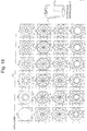
- Fig. 18 is an illustration showing a result of a computer simulation in which three-dimensional geometric information of a plane ( n d s0 and n s0 ) is determined from the positions p 0 , p 1 at the present time and the subsequent time and the position p inf after the infinite time elapses in accordance with the small circle transformation algorithm described in 2. 2. 3. In Fig. 18, there are shown the "sectional circles of cylinders at the respective normalization shortest distance parameters n d s " explained in connection with Fig. 17(B). Each of the sectional circles is obtained through a projection of the sphere of Fig. 17(A) onto a plane passing through the sphere in accordance with the "equidistant projection (cf.
- the azimuth of intersecting with one point is in the center of the visual field, and is equivalent to the "normal vector n s0 of the plane". From the above-mentioned simulation, it has been confirmed that the "small circle transformation algorithm" explained in 2. 2. 3 is correct. Incidentally, it has been confirmed through the simulation that the three-dimensional geometric information of a plane can be accurately determined in accordance with the method in 2. 1 too.
- the various block diagrams which will be explained hereinafter, may be understood as the functional blocks of the computer system 300 shown in Figs. 2 and 3, and also be understood as the various embodiments of an image measurement apparatus according to the present invention where the image measurement apparatus is constructed with the hardware.
- the various flowcharts which will be explained hereinafter, may be understood as the various embodiments of the image measurement programs referred to in the present invention, which are executed when they are installed in the computer system 300 shown in Figs. 2 and 3, and also be understood as the various embodiments of an image measurement method according to the present invention.
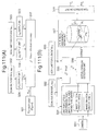
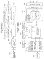
- Figs. 111(A) and 111(B) are block diagrams of an embodiment E-1 of the present invention.
- Figs. 112 and 113 are flowcharts of the embodiment E-1.
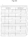
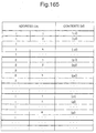
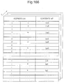
- the following motion direction (a direction of motion from i p 0 to i p 1 , that is, ij ⁇ ) and the like are omitted.
- ij ⁇ is determined from p 1 computed in (A) of the appendix to form the content of an ij ⁇ table, and further there is a need to vote only when ij ⁇ is coincident with a direction t a n -1 ( ij ⁇ y / ij ⁇ x ) of the motion vector ( ij ⁇ x , ij ⁇ y ) to be detected in the following step ( ⁇ 5).
- those are omitted. In this respect, it is the same also in the embodiments involving the similar processing, which will be described hereinafter.
- the motion parallax ij ⁇ is computed in accordance with any one of methods, not restricted to the method shown in (A-1) of the appendix. In this respect, it is the same also in all the embodiments in which a computation of motion parallax is performed in accordance with the method shown in (A-1) of the appendix.
- the ij ⁇ table is prepared, and in the actual voting, ij ⁇ is derived from the ij ⁇ table thus prepared.
- ij ⁇ is computed when an operation for the voting is carried out.
- Figs. 114(A) and 114(B) are block diagrams of an embodiment E-2 of the present invention.
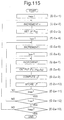
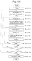
- Figs. 115 and 116 are flowcharts of the embodiment E-2.
- step ( ⁇ 2) to ( ⁇ 6) are the same as the corresponding steps of the embodiment E-1( ⁇ ).
- step ( ⁇ 1) to ( ⁇ 6) are the same as the corresponding steps of the embodiment E-1.
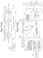
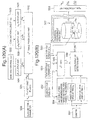
- Figs. 117(A) and 117(B) are block diagrams of an embodiment E-3 of the present invention.
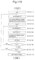
- Figs. 118 and 119 are flowcharts of the embodiment E-3.
- the motion parallax ij ⁇ is computed in accordance with any one of methods, not restricted to the method shown in (A-2) of the appendix. In this respect, it is the same also in all the embodiments in which a computation of motion parallax is performed in accordance with the method shown in (A-2) of the appendix.
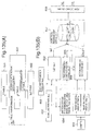
- Figs. 120(A) and 120(B) are block diagrams of an embodiment E-4 of the present invention.
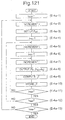
- Figs. 121 and 122 are flowcharts of the embodiment E-4.
- step ( ⁇ 2) to ( ⁇ 6) are the same as the corresponding steps of the embodiment E-3( ⁇ ).
- step ( ⁇ 1) to ( ⁇ 6) are the same as the corresponding steps of the embodiment E-3.
- Figs. 135(A) and 135(B) are block diagrams of an embodiment F-1 of the present invention.
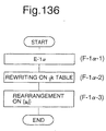
- Figs. 136 and 137 are flowcharts of the embodiment F-1.
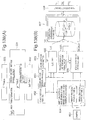
- Figs. 138(A) and 138(B) are block diagrams of an embodiment F-2 of the present invention.
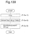
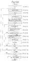
- Figs. 139 and 140 are flowcharts of the embodiment F-2.
- Figs. 141(A) and 141(B) are block diagrams of an embodiment F-3 of the present invention.
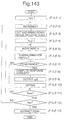
- Figs. 142 and 143 are flowcharts of the embodiment F-3.
- Figs. 144(A) and 144(B) are block diagrams of an embodiment F-4 of the present invention.
- Figs. 145 and 146 are flowcharts of the embodiment F-4.
- This method of determining a normalization shortest distance is very useful for a "separation of a plurality of objects and environments which look like that they are superposed" (referred to as a depth separation). That is, a "relative depth” and a “gradient” of a plane constituting the objects and the environments can be measured in the form of the normalization shortest distance n d s and the three-dimensional azimuth n s . Thus, it is possible to separate and identify the objects and the environments even if they are superposed.
- This depth separation is characterized in the point that only determination of the positions p 0 , p 1 and P inf at three times permits the separation, even if the moving velocity V and "time difference ⁇ t between the present time and the subsequent time and the moving distance ⁇ x" are unknown.
- a shortest distance d s to the plane it is possible to obtain the shortest distance d s by means of multiplying the "moving distance ⁇ x from the present time to the subsequent time" by the normalization shortest distance n d s .
Landscapes
- Engineering & Computer Science (AREA)
- Computer Vision & Pattern Recognition (AREA)
- Physics & Mathematics (AREA)
- General Physics & Mathematics (AREA)
- Theoretical Computer Science (AREA)
- Multimedia (AREA)
- Length Measuring Devices By Optical Means (AREA)
- Measurement Of Optical Distance (AREA)
- Image Processing (AREA)
- Image Analysis (AREA)
- Stereoscopic And Panoramic Photography (AREA)
Abstract

Description
- (I) Forward Direction Method
- (I-1) Normalized time An image measurement method according to paragraph (4) of paragraph (16), wherein a response intensity obtained by a method (or an apparatus) of detecting a motion parallax is voted.
- (I-2) Normalized time + v unknown An image measurement method according to paragraphs (7) and (4) of paragraph (16), wherein a response intensity obtained by a method (or an apparatus) of detecting a motion parallax is voted.
- (I-3) Normalization Shortest Distance An image measurement method according to paragraph (10) of paragraph (16), wherein a response intensity obtained by a method (or an apparatus) of detecting a motion parallax is voted.
- (I-4) Normalization Shortest Distance + v unknown An image measurement method according to paragraphs (13) and (10) of paragraph (16), wherein a response intensity obtained by a method (or an apparatus) of detecting a motion parallax is voted.
- (I-5) Stereo + Normalized distance An image measurement method according to paragraphs (17) and (4) of paragraph (20), wherein a response intensity obtained by a method (or an apparatus) of detecting a binocular parallax is voted.
- (I-6) Stereo + Normalized distance + axis unknown An image measurement method according to paragraphs (17), (7) and (4) of paragraph (20), wherein a response intensity obtained by a method (or an apparatus) of detecting a binocular parallax is voted.
- (I-7) Stereo + Normalization Shortest Distance An image measurement method according to paragraphs (18) and (10) of paragraph (20), wherein a response intensity obtained by a method (or an apparatus) of detecting a binocular parallax is voted.
- (I-8) Stereo + Normalization Shortest Distance + axis unknown An image measurement method according to paragraphs (18), (13) and (10) of paragraph (20), wherein a response intensity obtained by a method (or an apparatus) of detecting a binocular parallax is voted.
- (I-9) Normalization Shortest Distance An image measurement method according to paragraph (9) of paragraph (16), wherein a response intensity obtained by a method (or an apparatus) of detecting a motion parallax is voted.
- (I-10) Normalization Shortest Distance + v unknown An image measurement method according to paragraphs (13) and (9) of paragraph (16), wherein a response intensity obtained by a method (or an apparatus) of detecting a motion parallax is voted.
- (I-11) Stereo + Normalization Shortest Distance An image measurement method according to paragraphs (18) and (9) of paragraph (20), wherein a response intensity obtained by a method (or an apparatus) of detecting a binocular parallax is voted.
- (I-12) Stereo + Normalization Shortest Distance + axis unknown An image measurement method according to paragraphs (18), (13) and (9) of paragraph (20), wherein a response intensity obtained by a method (or an apparatus) of detecting a binocular parallax is voted.





"the normalized time ntc is coordinates of pc which is measured by a basic point system wherein the original point, the infinite-point and the unit point are given by p0, pinf , p1, respectively". (12b)
Incidentally, intensity of the large circle corresponds to "brightness of position p0 in an image", and in the place wherein a plurality of large circles intersect with each other, intensity of the large circles is added.




Claims (48)
- An image measurement method comprising :wherein the second step to the fourth step, of the first to fourth steps, are effected by a plurality of number of times on a plurality of measuring points in the measurement space, while a value of the parameter is altered in the first step.a first step of setting up coordinates in a voting space in form of a parameter, said coordinates being defined by a physical quantity indexing a superposing time in which a measuring plane, including an arbitrary measuring point appearing on an image obtained through viewing a predetermined measurement space from a predetermined observation point inside the measurement space, is superposed on the observation point, and an azimuth ns of the measuring plane, in a moving continuous state wherein it is expected that a movement of the measuring point appearing on an image obtained through viewing the measurement space from the observation point inside the measurement space, said measuring point being relative with respect to the observation point, is continued in a direction identical to a moving direction relative with respect to the observation point between mutually different two measuring times on the measuring point and at a velocity identical to a moving velocity between said two measuring times;a second step of determining a motion parallax τ, which is a positional difference between two measuring positions p0 and p1 at the two measuring times on the measuring point, in accordance with a measuring position p0 at one measuring time of said two measuring times on said measuring point, a position pinf of the measuring point after an infinite time elapses in the moving continuous state, and the coordinates in the voting space, which is set up in the first step;a third step of determining a response intensity associated with the motion parallax τ of the measuring point in accordance with two images obtained through viewing the measurement space from the observation point at the two measuring times; anda fourth step of voting the response intensity determined in the third step for the coordinates in the voting space, which is set up in the first step,
- An image measurement method comprising :wherein the third step to the fifth step, of the first to fifth steps, are effected by a plurality of number of times on a plurality of measuring points in the measurement space, while values of the parameters are altered in the first step and the second step.a first step of setting up in form of a first parameter a moving direction v of an arbitrary measuring point appearing on an image obtained through viewing a predetermined measurement space from a predetermined observation point inside the measurement space, said moving direction being relative with respect to the observation point between mutually different two measuring times, and setting up a position pinf of the measuring point after an infinite time elapses in a moving continuous state wherein it is expected that a movement of the measuring point is continued in a direction identical to the moving direction v and at a velocity identical to a moving velocity between the two measuring times;a second step of setting up coordinates in a voting space according to the first parameter in form of a second parameter, said coordinates being defined by a physical quantity indexing a superposing time in which a measuring plane including the measuring point is superposed on the observation point, and an azimuth ns of the measuring plane;a third step of determining a motion parallax τ, which is a positional difference between two measuring positions p0 and p1 at the two measuring times on the measuring point, in accordance with a measuring position p0 at one measuring time of said two measuring times on said measuring point, a position pinf set up in the first step, and the coordinates in the voting space, which is set up in the second step;a fourth step of determining a response intensity associated with the motion parallax τ of the measuring point in accordance with two images obtained through viewing the measurement space from the observation point at the two measuring times; anda fifth step of voting the response intensity determined in the fourth step for the coordinates in the voting space according to the first parameter, said coordinates being set up in the second step,
- An image measurement method comprising :wherein the second step to the fourth step, of the first to fourth steps, are effected by a plurality of number of times on a plurality of measuring points in the measurement space, while a value of the parameter is altered in the first step.a first step of setting up coordinates in a voting space in form of a parameter, said coordinates being defined by a physical quantity indexing a shortest distance between a predetermined observation point inside a predetermined measurement space for observation of the measurement space and a measuring plane, including an arbitrary measuring point appearing on an image obtained through viewing the measurement space from the observation point inside the measurement space, at one measuring time of mutually different two measuring times, and an azimuth ns of the measuring plane;a second step of determining a motion parallax τ, which is a positional difference between two measuring positions p0 and p1 at the two measuring times on the measuring point, in accordance with a measuring position p0 at one measuring time of the two measuring times on the measuring point, a position pinf of the measuring point after an infinite time elapses in a moving continuous state wherein it is expected that a movement of the measuring point is continued in a direction identical to a moving direction relative with respect to the observation point between mutually different two measuring times and at a velocity identical to a moving velocity between said two measuring times, and the coordinates in the voting space, which is set up in the first step;a third step of determining a response intensity associated with the motion parallax τ of the measuring point in accordance with two images obtained through viewing the measurement space from the observation point at the two measuring times; anda fourth step of voting the response intensity determined in the third step for the coordinates in the voting space, which is set up in the first step,
- An image measurement method comprising :wherein the third step to the fifth step, of the first to fifth steps, are effected by a plurality of number of times on a plurality of measuring points in the measurement space, while values of the parameters are altered in the first step and the second step.a first step of setting up in form of a first parameter a moving direction v of an arbitrary measuring point appearing on an image obtained through viewing a predetermined measurement space from a predetermined observation point inside the measurement space, said moving direction being relative with respect to the observation point between mutually different two measuring times, and setting up a position pinf of the measuring point after an infinite time elapses in a moving continuous state wherein it is expected that a movement of the measuring point is continued in a direction identical to the moving direction-v and at a velocity identical to a moving velocity between the two measuring times;a second step of setting up coordinates in a voting space according to the first parameter in form of a second parameter, said coordinates being defined by a physical quantity indexing a shortest distance from the observation point to a measuring plane including the measuring point at one measuring time of the two measuring times, and an azimuth ns of the measuring plane;a third step of determining a motion parallax τ, which is a positional difference between two measuring positions p0 and p1 at the two measuring times on the measuring point, in accordance with a measuring position p0 at one measuring time of said two measuring times on said measuring point, a position pinf set up in the first step, and the coordinates in the voting space, which is set up in the second step;a fourth step of determining a response intensity associated with the motion parallax τ of the measuring point in accordance with two images obtained through viewing the measurement space from the observation point at the two measuring times; anda fifth step of voting the response intensity determined in the fourth step for the coordinates in the voting space according to the first parameter, said coordinates being set up in the second step,
- An image measurement method comprising :wherein the second step to the fourth step, of the first to fourth steps, are effected by a plurality of number of times on a plurality of measuring points in the measurement space, while a value of the parameter is altered in the first step.a first step of setting up in form of a parameter a motion parallax τ, which is a positional difference between two measuring positions p0 and p1 at mutually different two measuring times, of an arbitrary measuring point appearing on an image obtained through viewing a predetermined measurement space from a predetermined observation point inside the measurement space;a second step of determining coordinates in a voting space, said coordinates being defined by a physical quantity indexing a superposing time in which a measuring plane, including the measuring point, is superposed on the observation point, and an azimuth ns of the measuring plane, in a moving continuous state wherein it is expected that a movement of the measuring point, said measuring point being relative with respect to the observation point, is continued in a direction identical to a moving direction relative with respect to the observation point between the two measuring times on the measuring point and at a velocity identical to a moving velocity between the two measuring times, in accordance with a measuring position p0 at one measuring time of said two measuring times on said measuring point, a position pinf of the measuring point after an infinite time elapses in the moving continuous state, and the motion parallax τ set up in the first step;a third step of determining a response intensity associated with the motion parallax τ of the measuring point, which is set up in the first step, in accordance with two images obtained through viewing the measurement space from the observation point at the two measuring times; anda fourth step of voting the response intensity determined in the third step for the coordinates in the voting space, said coordinates being set up in the second step,
- An image measurement method comprising :wherein the third step to the fifth step, of the first to fifth steps, are effected by a plurality of number of times on a plurality of measuring points in the measurement space, while values of the parameters are altered in the first step and the second step.a first step of setting up in form of a first parameter a moving direction v of an arbitrary measuring point appearing on an image obtained through viewing a predetermined measurement space from a predetermined observation point inside the measurement space, said moving direction being relative with respect to the observation point between mutually different two measuring times, and setting up a position pinf of the measuring point after an infinite time elapses in a moving continuous state wherein it is expected that a movement of the measuring point is continued in a direction identical to the moving direction v and at a velocity identical to a moving velocity between the two measuring times;a second step of setting up in form of a second parameter a motion parallax τ, which is a positional difference between two measuring positions p0 and p1 at the two measuring times on the measuring point;a third step of determining coordinates in a voting space according to the first parameter, said coordinates being defined by a physical quantity indexing a superposing time in which a measuring plane, including the measuring point, is superposed on the observation point, and an azimuth ns of the measuring plane, in the moving continuous state, in accordance with a measuring position p0 at one measuring time of said two measuring times on the measuring point, a position pinf set up in the first step, and the motion parallax τ set up in the second step;a fourth step of determining a response intensity associated with the motion parallax τ of the measuring point, which is set up in the second step, in accordance with two images obtained through viewing the measurement space from the observation point at the two measuring times; anda fifth step of voting the response intensity determined in the fourth step for the coordinates in the voting space according to the first parameter, said coordinates being set up in the third step,
- An image measurement method comprising :wherein the second step to the fourth step, of the first to fourth steps, are effected by a plurality of number of times on a plurality of measuring points in the measurement space, while a value of the parameter is altered in the first step.a first step of setting up in form of a parameter a motion parallax τ, which is a positional difference between two measuring positions p0 and p1 at mutually different two measuring times on the measuring point, of an arbitrary measuring point appearing on an image obtained through viewing a predetermined measurement space from a predetermined observation point inside the measurement space;a second step of determining coordinates in a voting space, said coordinates being defined by a physical quantity indexing a shortest distance from the observation point to a measuring plane including the measuring point at one measuring time of the two measuring times, and an azimuth ns of the measuring plane, in accordance with a measuring position p0 at one measuring time of said two measuring times on said measuring point, a position pinf of the measuring point after an infinite time elapses in a moving continuous state wherein it is expected that a movement of the measuring point, said measuring point being relative with respect to the observation point, is continued in a direction identical to a moving direction relative with respect to the observation point between the two measuring times on the measuring point and at a velocity identical to a moving velocity between the two measuring times, and the motion parallax τ set up in the first step;a third step of determining a response intensity associated with the motion parallax τ of the measuring point, which is set up in the first step, in accordance with two images obtained through viewing the measurement space from the observation point at the two measuring times; anda fourth step of voting the response intensity determined in the third step for the coordinates in the voting space, said coordinates being set up in the second step,
- An image measurement method comprising :wherein the third step to the fifth step, of the first to fifth steps, are effected by a plurality of number of times on a plurality of measuring points in the measurement space, while values of the parameters are altered in the first step and the second step.a first step of setting up in form of a first parameter a moving direction v of an arbitrary measuring point appearing on an image obtained through viewing a predetermined measurement space from a predetermined observation point inside the measurement space, said moving direction being relative with respect to the observation point between mutually different two measuring times, and setting up a position pinf of the measuring point after an infinite time elapses in a moving continuous state wherein it is expected that a movement of the measuring point is continued in a direction identical to the moving direction v and at a velocity identical to a moving velocity between the two measuring times;a second step of setting up in form of a second parameter a motion parallax τ, which is a positional difference between two measuring positions p0 and p1 at the two measuring times on the measuring point;a third step of determining coordinates in a voting space according to the first parameter, said coordinates being defined by a physical quantity indexing a shortest distance from the observation point to a measuring plane including the measuring point at one measuring time of the two measuring times, and an azimuth ns of the measuring plane, in the moving continuous state, in accordance with a measuring position p0 at one measuring time of said two measuring times on the measuring point, a position pinf set up in the first step, and the motion parallax τ set up in the second step;a fourth step of determining a response intensity associated with the motion parallax τ of the measuring point, which is set up in the second step, in accordance with two images obtained through viewing the measurement space from the observation point at the two measuring times; anda fifth step of voting the response intensity determined in the fourth step for the coordinates in the voting space according to the first parameter, said coordinates being set up in the third step,
- An image measurement method comprising :wherein the first step and the second step are effected by a plurality of number of times on a plurality of measuring points in the measurement space.a first step of determining a response intensity associated with a motion parallax, which is a positional difference between two measuring positions at mutually different two measuring times, of an arbitrary measuring point in a predetermined measurement space, in accordance with two images obtained through viewing the measurement space from a predetermined observation point at mutually different two measuring times; anda second step of voting the response intensity determined in the first step for coordinates associated with the measuring point and the motion parallax in a voting space, said coordinates being defined by a physical quantity indexing a superposing time in which a measuring plane, including the measuring point, is superposed on the observation point, and an azimuth of the measuring plane, in a moving continuous state wherein it is expected that a movement of the measuring point, said measuring point being relative with respect to the observation point, is continued in a direction identical to a moving direction relative with respect to the observation point between the two measuring times on the measuring point and at a velocity identical to a moving velocity between the two measuring times;
- An image measurement method according to claim 9, wherein said image measurement method further comprises a third step of determining an azimuth of a measuring plane including a plurality of measuring points joining a voting for a maximal point and/or a physical quantity indexing a superposing time in which the measuring plane is superposed on the observation point in such a manner that a maximal point wherein a value by said voting in the voting space offers a maximal value is determined.
- An image measurement method comprising :wherein the second step and the third step, of the first to third steps, are effected by a plurality of number of times on a plurality of measuring points in the measurement space, while a value of the parameter is altered in the first step.a first step of setting up in form of a parameter a moving direction of an arbitrary measuring point appearing on an image obtained through viewing a predetermined measurement space from a predetermined observation point inside the measurement space, said moving direction being relative with respect to the observation point between mutually different two measuring times;a second step of determining a response intensity associated with a motion parallax, which is a positional difference between two measuring positions at the two measuring times on the measuring point, in accordance with two images obtained through viewing the measurement space from the observation point at the two measuring times; anda third step of voting the response intensity determined in the second step for coordinates associated with the measuring point and the motion parallax in a voting space according to the parameter set up in the first step, said coordinates being defined by a physical quantity indexing a superposing time in which a measuring plane, including the measuring point, is superposed on the observation point, and an azimuth of the measuring plane, in a moving continuous state wherein it is expected that a movement of the measuring point, said measuring point being relative with respect to the observation point, is continued in a direction identical to a moving direction relative with respect to the observation point between the two measuring times on the measuring point and at a velocity identical to a moving velocity between the two measuring times;
- An image measurement method according to claim 11, wherein said image measurement method further comprises a fourth step of determining a true moving direction relative to the observation point on the measuring point, and of determining an azimuth of a measuring plane including a plurality of measuring points joining a voting for a maximal point determined on a voting space associated with the true moving direction, and/or a physical quantity indexing a superposing time in which the measuring plane is superposed on the observation point, in such a manner that a maximal point wherein a value by a voting is determined on each voting space, and the voting space associated with the true moving direction is selected in accordance with information as to the maximal value on the maximal point.
- An image measurement method comprising:wherein the first step and the second step are effected by a plurality of number of times on a plurality of measuring points in the. measurement space.a first step of determining a response intensity associated with a motion parallax, which is a positional difference between two measuring positions at mutually different two measuring times, of an arbitrary measuring point in a predetermined measurement space, in accordance with two images obtained through viewing the measurement space from a predetermined observation point at mutually different two measuring times; anda second step of voting the response intensity determined in the first step for coordinates associated with the measuring point and the motion parallax in a voting space, said coordinates being defined by a physical quantity indexing a shortest distance from the observation point to a measuring plane, including the measuring point, at one measuring time of the two measuring times, and an azimuth of the measuring plane;
- An image measurement method according to claim 13, wherein said image measurement method further comprises a third step of determining an azimuth of a measuring plane including a plurality of measuring points joining a voting for a maximal point and/or a physical quantity indexing a shortest distance from the observation point to the measuring plane at one measuring time of the two measuring times in such a manner that a maximal point wherein a value by said voting offers a maximal value is determined in the voting space.
- An image measurement method comprising :wherein the second step and the third step, of the first to third steps, are effected by a plurality of number of times on a plurality of measuring points in the measurement space, while a value of the parameter is altered in the first step.a first step of setting up in form of a parameter a moving direction of an arbitrary measuring point appearing on an image obtained through viewing a predetermined measurement space from a predetermined observation point inside the measurement space, said moving direction being relative with respect to the observation point between mutually different two measuring times;a second step of determining a response intensity associated with a motion parallax, which is a positional difference between two measuring positions at the two measuring times on the measuring point, in accordance with two images obtained through viewing the measurement space from the observation point at the two measuring times; anda third step of voting the response intensity determined in the second step for coordinates associated with the measuring point and the motion parallax in a voting space according to the parameter set up in the first step, said coordinates being defined by a physical quantity indexing a shortest distance from the observation point to the measuring plane at one measuring time of the two measuring times, including the measuring point, and an azimuth of the measuring plane;
- An image measurement method according to claim 15, wherein said image measurement method further comprises a fourth step of determining a true moving direction, and of determining an azimuth of a measuring plane including a plurality of measuring points joining a voting for a maximal point determined on a voting space associated with the true moving direction, and/or a shortest distance from the observation point to the measuring plane at one measuring time of the two measuring times, in such a manner that a maximal point wherein a value by said voting offers a maximal value is determined on each voting space, and a voting space associated with the true moving direction relative to the observation point on the measuring point is selected in accordance with information as to the maximal value on the maximal point.
- An image measurement apparatus comprising :wherein said motion parallax operating unit, said response intensity operating unit, and said voting unit perform operations by a plurality of number of times on a plurality of measuring points in the measurement space, while a value of the parameter is altered in said parameter setting unit.a parameter setting unit for setting up coordinates in a voting space in form of a parameter, said coordinates being defined by a physical quantity indexing a superposing time in which a measuring plane, including an arbitrary measuring point appearing on an image obtained through viewing a predetermined measurement space from a predetermined observation point inside the measurement space, is superposed on the observation point, and an azimuth ns of the measuring plane, in a moving continuous state wherein it is expected that a movement of the measuring point appearing on an image obtained through viewing the measurement space from the observation point inside the measurement space, said measuring point being relative with respect to the observation point, is continued in a direction identical to a moving direction relative with respect to the observation point between mutually different two measuring times on the measuring point and at a velocity identical to a moving velocity between said two measuring times;a motion parallax operating unit for determining a motion parallax τ, which is a positional difference between two measuring positions p0 and p1 at the two measuring times on the measuring point, in accordance with a measuring position p0 at one measuring time of said two measuring times on said measuring point, a position pinf of the measuring point after an infinite time elapses in the moving continuous state, and the coordinates in the voting space, which is set up in said parameter setting unit;a response intensity operating unit for determining a response intensity associated with the motion parallax τ of the measuring point in accordance with two images obtained through viewing the measurement space from the observation point at the two measuring times; anda voting unit for voting the response intensity determined in said response intensity operating unit for the coordinates in the voting space, which is set up in said parameter setting unit,
- An image measurement apparatus comprising :wherein said motion parallax operating unit, said response intensity operating unit, and said voting unit perform operations by a plurality of number of times on a plurality of measuring points in the measurement space, while values of the parameters are altered in the first parameter setting unit and said second parameter setting unit.a first parameter setting unit for setting up in form of a first parameter a moving direction v of an arbitrary measuring point appearing on an image obtained through viewing a predetermined measurement space from a predetermined observation point inside the measurement space, said moving direction being relative with respect to the observation point between mutually different two measuring times, and setting up a position pinf of the measuring point after an infinite time elapses in a moving continuous state wherein it is expected that a movement of the measuring point is continued in a direction identical to the moving direction v and at a velocity identical to a moving velocity between the two measuring times;a second parameter setting unit for setting up coordinates in a voting space according to the first parameter in form of a second parameter, said coordinates being defined by a physical quantity indexing a superposing time in which a measuring plane including the measuring point is superposed on the observation point, and an azimuth ns of the measuring plane;a motion parallax operating unit for determining a motion parallax τ, which is a positional difference between two measuring positions p0 and p1 at the two measuring times on the measuring point, in accordance with a measuring position p0 at one measuring time of said two measuring times on said measuring point, a position pinf set up in said first parameter setting unit, and the coordinates in the voting space, which is set up in said second parameter setting unit;a response intensity operating unit for determining a response intensity associated with the motion parallax τ of the measuring point in accordance with two images obtained through viewing the measurement space from the observation point at the two measuring times; anda voting unit for voting the response intensity determined in said response intensity operating unit for the coordinates in the voting space according to the first parameter, said coordinates being set up in the second parameter setting unit,
- An image measurement apparatus comprising :wherein said motion parallax operating unit, said response intensity operating unit, and said voting unit perform operations by a plurality of number of times on a plurality of measuring points in the measurement space, while a value of the parameter is altered in said parameter setting unit .a parameter setting unit for setting up coordinates in a voting space in form of a parameter, said coordinates being defined by a physical quantity indexing a shortest distance between a predetermined observation point inside a predetermined measurement space for observation of the measurement space and a measuring plane, including an arbitrary measuring point appearing on an image obtained through viewing the measurement space from the observation point inside the measurement space, at one measuring time of mutually different two measuring times, and an azimuth ns of the measuring plane;a motion parallax operating unit for determining a motion parallax τ, which is a positional difference between two measuring positions p0 and p1 at the two measuring times on the measuring point, in accordance with a measuring position p0 at one measuring time of the two measuring times on the measuring point, a position pinf of the measuring point after an infinite time elapses in a moving continuous state wherein it is expected that a movement of the measuring point is continued in a direction identical to a moving direction relative with respect to the observation point between mutually different two measuring times and at a velocity identical to a moving velocity between said two measuring times, and the coordinates in the voting space, which is set up in said parameter setting unit;;a response intensity operating unit for determining a response intensity associated with the motion parallax τ of the measuring point in accordance with two images obtained through viewing the measurement space from the observation point at the two measuring times; anda voting unit for voting the response intensity determined in said response intensity operating unit for the coordinates in the voting space, which is set up in said parameter setting unit;,
- An image measurement apparatus comprising :wherein said motion parallax operating unit, said response intensity operating unit, and said voting unit perform operations by a plurality of number of times on a plurality of measuring points in the measurement space, while values of the parameters are altered in said first parameter setting unit and said second parameter setting unit.a first parameter setting unit for setting up in form of a first parameter a moving direction v of an arbitrary measuring point appearing on an image obtained through viewing a predetermined measurement space from a predetermined observation point inside the measurement space, said moving direction being relative with respect to the observation point between mutually different two measuring times, and setting up a position pinf of the measuring point after an infinite time elapses in a moving continuous state wherein it is expected that a movement of the measuring point is continued in a direction identical to the moving direction v and at a velocity identical to a moving velocity between the two measuring times;a second parameter setting unit for setting up coordinates in a voting space according to the first parameter in form of a second parameter, said coordinates being defined by a physical quantity indexing a shortest distance from the observation point to a measuring plane including the measuring point at one measuring time of the two measuring times, and an azimuth ns of the measuring plane;a motion parallax operating unit for determining a motion parallax τ, which is a positional difference between two measuring positions p0 and p1 at the two measuring times on the measuring point, in accordance with a measuring position p0 at one measuring time of said two measuring times on said measuring point, a position pinf set up in said first parameter setting unit, and the coordinates in the voting space, which is set up in said second parameter setting unit;a response intensity operating unit for determining a response intensity associated with the motion parallax τ of the measuring point in accordance with two images obtained through viewing the measurement space from the observation point at the two measuring times; anda voting unit for voting the response intensity determined in said response intensity operating unit for the coordinates in the voting space according to the first parameter, said coordinates being set up in said second parameter setting unit,
- An image measurement apparatus comprising :wherein said coordinates operating unit, said response intensity operating unit, and said voting unit perform operations by a plurality of number of times on a plurality of measuring points in the measurement space, while a value of the parameter is altered in said parameter setting unit.a parameter setting unit for setting up in form of a parameter a motion parallax τ, which is a positional difference between two measuring positions p0 and p1 at mutually different two measuring times, of an arbitrary measuring point appearing on an image obtained through viewing a predetermined measurement space from a predetermined observation point inside the measurement space;a coordinates operating unit for determining coordinates in a voting space, said coordinates being defined by a physical quantity indexing a superposing time in which a measuring plane, including the measuring point, is superposed on the observation point, and an azimuth ns of the measuring plane, in a moving continuous state wherein it is expected that a movement of the measuring point, said measuring point being relative with respect to the observation point, is continued in a direction identical to a moving direction relative with respect to the observation point between the two measuring times on the measuring point and at a velocity identical to a moving velocity between the two measuring times, in accordance with a measuring position p0 at one measuring time of said two measuring times on said measuring point, a position pinf of the measuring point after an infinite time elapses in the moving continuous state, and the motion parallax τ set up in said parameter setting unit;a response intensity operating unit for determining a response intensity associated with the motion parallax τ of the measuring point, which is set up in said parameter setting unit;, in accordance with two images obtained through viewing the measurement space from the observation point at the two measuring times; anda voting unit for voting the response intensity determined in said response intensity operating unit for the coordinates in the voting space, said coordinates being set up in said coordinates operating unit,
- An image measurement apparatus comprising :wherein said coordinates operating unit, said response intensity operating unit, and said voting unit perform operations by a plurality of number of times on a plurality of measuring points in the measurement space, while values of the parameters are altered in the first parameter setting unit and said second parameter setting unit.a first parameter setting unit for setting up in form of a first parameter a moving direction v of an arbitrary measuring point appearing on an image obtained through viewing a predetermined measurement space from a predetermined observation point inside the measurement space, said moving direction being relative with respect to the observation point between mutually different two measuring times, and setting up a position pinf of the measuring point after an infinite time elapses in a moving continuous state wherein it is expected that a movement of the measuring point is continued in a direction identical to the moving direction v and at a velocity identical to a moving velocity between the two measuring times;a second parameter setting unit for setting up in form of a second parameter a motion parallax τ, which is a positional difference between two measuring positions p0 and p1 at the two measuring times on the measuring point;a coordinates operating unit for determining coordinates in a voting space according to the first parameter, said coordinates being defined by a physical quantity indexing a superposing time in which a measuring plane, including the measuring point, is superposed on the observation point, and an azimuth ns of the measuring plane, in the moving continuous state, in accordance with a measuring position p0 at one measuring time of said two measuring times on the measuring point, a position pinf set up in said first parameter setting unit, and the motion parallax τ set up in said second parameter setting unit;a response intensity operating unit for determining a response intensity associated with the motion parallax τ of the measuring point, which is set up in said second parameter setting unit, in accordance with two images obtained through viewing the measurement space from the observation point at the two measuring times; anda voting unit for voting the response intensity determined in said response intensity operating unit for the coordinates in the voting space according to the first parameter, said coordinates being set up in the coordinates operating unit,
- An image measurement apparatus comprising:wherein said coordinates parallax operating unit, said response intensity operating unit, and said voting unit perform operations by a plurality of number of times on a plurality of measuring points in the measurement space, while a value of the parameter is altered in said parameter setting unit .a parameter setting unit for setting up in form of a parameter a motion parallax τ, which is a positional difference between two measuring positions p0 and p1 at mutually different two measuring times on the measuring point, of an arbitrary measuring point appearing on an image obtained through viewing a predetermined measurement space from a predetermined observation point inside the measurement space;a coordinates operating unit for determining coordinates in a voting space, said coordinates being defined by a physical quantity indexing a shortest distance from the observation point to a measuring plane including the measuring point at one measuring time of the two measuring times, and an azimuth ns of the measuring plane, in accordance with a measuring position p0 at one measuring time of said two measuring times on said measuring point, a position pinf of the measuring point after an infinite time elapses in a moving continuous state wherein it is expected that a movement of the measuring point, said measuring point being relative with respect to the observation point, is continued in a direction identical to a moving direction relative with respect to the observation point between the two measuring times on the measuring point and at a velocity identical to a moving velocity between the two measuring times, and the motion parallax τ set up in the first parameter setting unit;a response intensity operating unit for determining a response intensity associated with the motion parallax τ of the measuring point, which is set up in said parameter setting unit, in accordance with two images obtained through viewing the measurement space from the observation point at the two measuring times; anda voting unit for voting the response intensity determined in said response intensity operating unit for the coordinates in the voting space, said coordinates being set up in said coordinates operating unit,
- An image measurement apparatus comprising :wherein said coordinates operating unit, and said voting unit perform operations by a plurality of number of times on a plurality of measuring points in the measurement space, while values of the parameters are altered in the first parameter setting unit and said second parameter setting unit.a first parameter setting unit for setting up in form of a first parameter a moving direction v of an arbitrary measuring point appearing on an image obtained through viewing a predetermined measurement space from a predetermined observation point inside the measurement space, said moving direction being relative with respect to the observation point between mutually different two measuring times, and setting up a position pinf of the measuring point after an infinite time elapses in a moving continuous state wherein it is expected that a movement of the measuring point is continued in a direction identical to the moving direction v and at a velocity identical to a moving velocity between the two measuring times;a second parameter setting unit for setting up in form of a second parameter a motion parallax τ, which is a positional difference between two measuring positions p0 and p1 at the two measuring times on the measuring point;a coordinates operating unit for determining coordinates in a voting space according to the first parameter, said coordinates being defined by a physical quantity indexing a shortest distance from the observation point to a measuring plane including the measuring point at one measuring time of the two measuring times, and an azimuth ns of the measuring plane, in the moving continuous state, in accordance with a measuring position p0 at one measuring time of said two measuring times on the measuring point, a position pinf set up in said first parameter setting unit, and the motion parallax τ set up in said second parameter setting unit;a response intensity operating unit for determining a response intensity associated with the motion parallax τ of the measuring point, which is set up in said second parameter setting unit, in accordance with two images obtained through viewing the measurement space from the observation point at the two measuring times; anda voting unit for voting the response intensity determined in said response intensity operating unit for the coordinates in the voting space according to the first parameter, said coordinates being set up in said coordinates operating unit,
- An image measurement apparatus comprising :wherein said response intensity operating unit and said voting unit perform operation by a plurality of number of times on a plurality of measuring points in the measurement space.a response intensity operating unit for determining a response intensity associated with a motion parallax, which is a positional difference between two measuring positions at mutually different two measuring times, of an arbitrary measuring point in a predetermined measurement space, in accordance with two images obtained through viewing the measurement space from a predetermined observation point at mutually different two measuring times; anda voting unit for of voting the response intensity determined in said response intensity operating unit for coordinates associated with the measuring point and the motion parallax in a voting space, said coordinates being defined by a physical quantity indexing a superposing time in which a measuring plane, including the measuring point, is superposed on the observation point, and an azimuth of the measuring plane, in a moving continuous state wherein it is expected that a movement of the measuring point, said measuring point being relative with respect to the observation point, is continued in a direction identical to a moving direction relative with respect to the observation point between the two measuring times on the measuring point and at a velocity identical to a moving velocity between the two measuring times;
- An image measurement apparatus according to claim 25, wherein said image measurement apparatus further comprises a detection unit for determining an azimuth of a measuring plane including a plurality of measuring points joining a voting for a maximal point and/or a physical quantity indexing a superposing time in which the measuring plane is superposed on the observation point in such a manner that a maximal point wherein a value by said voting in the voting space offers a maximal value is determined.
- An image measurement apparatus comprising :wherein said response intensity operating unit and said voting unit perform operations by a plurality of number of times on a plurality of measuring points in the measurement space, while a value of the parameter is altered in said parameter setting unit.a parameter setting unit for setting up in form of a parameter a moving direction of an arbitrary measuring point appearing on an image obtained through viewing a predetermined measurement space from a predetermined observation point inside the measurement space, said moving direction being relative with respect to the observation point between mutually different two measuring times;a response intensity operating unit for determining a response intensity associated with a motion parallax, which is a positional difference between two measuring positions at the two measuring times on the measuring point, in accordance with two images obtained through viewing the measurement space from the observation point at the two measuring times; anda voting unit of voting the response intensity determined in said response intensity operating unit for coordinates associated with the measuring point and the motion parallax in a voting space according to the parameter set up in the parameter setting unit, said coordinates being defined by a physical quantity indexing a superposing time in which a measuring plane, including the measuring point, is superposed on the observation point, and an azimuth of the measuring plane, in a moving continuous state wherein it is expected that a movement of the measuring point, said measuring point being relative with respect to the observation point, is continued in a direction identical to a moving direction relative with respect to the observation point between the two measuring times on the measuring point and at a velocity identical to a moving velocity between the two measuring times;
- An image measurement apparatus according to claim 27, wherein said image measurement apparatus further comprises a detection unit of determining a true moving direction relative to the observation point on the measuring point, and of determining an azimuth of a measuring plane including a plurality of measuring points joining a voting for a maximal point determined on a voting space associated with the true moving direction, and/or a physical quantity indexing a superposing time in which the measuring plane is superposed on the observation point, in such a manner that a maximal point wherein a value by a voting is determined on each voting space, and the voting space associated with the true moving direction is selected in accordance with information as to the maximal value on the maximal point.
- An image measurement apparatus comprising:wherein said response intensity operating unit and said voting unit perform operations by a plurality of number of times on a plurality of measuring points in the measurement space.a response intensity operating unit for determining a response intensity associated with a motion parallax, which is a positional difference between two measuring positions at mutually different two measuring times, of an arbitrary measuring point in a predetermined measurement space, in accordance with two images obtained through viewing the measurement space from a predetermined observation point at mutually different two measuring times; anda voting unit for voting the response intensity determined in said response intensity operating unit for coordinates associated with the measuring point and the motion parallax in a voting space, said coordinates being defined by a physical quantity indexing a shortest distance from the observation point to a measuring plane, including the measuring point, at one measuring time of the two measuring times, and an azimuth of the measuring plane;
- An image measurement apparatus according to claim 29, wherein said measurement apparatus further comprises a detection unit for determining an azimuth of a measuring plane including a plurality of measuring points joining a voting for a maximal point and/or a physical quantity indexing a shortest distance from the observation point to the measuring plane at one measuring time of the two measuring times in such a manner that a maximal point wherein a value by said voting offers a maximal value is determined in the voting space.
- An image measurement apparatus comprising :wherein said response intensity operating unit and said voting unit perform operations by a plurality of number of times on a plurality of measuring points in the measurement space, while a value of the parameter is altered in said parameter setting unit .a parameter setting-unit for setting up in form of a parameter a moving direction of an arbitrary measuring point appearing on an image obtained through viewing a predetermined measurement space from a predetermined observation point inside the measurement space, said moving direction being relative with respect to the observation point between mutually different two measuring times;a response intensity operating unit for determining a response intensity associated with a motion parallax, which is a positional difference between two measuring positions at the two measuring times on the measuring point, in accordance with two images obtained through viewing the measurement space from the observation point at the two measuring times; anda voting unit for voting the response intensity determined in said response intensity operating unit for coordinates associated with the measuring point and the motion parallax in a voting space according to the parameter set up in said parameter setting unit, said coordinates being defined by a physical quantity indexing a shortest distance from the observation point to the measuring plane at one measuring time of the two measuring times, including the measuring point, and an azimuth of the measuring plane;
- An image measurement apparatus according to claim 31, wherein said image measurement apparatus further comprises a detection unit for determining a true moving direction, and determining an azimuth of a measuring plane including a plurality of measuring points joining a voting for a maximal point determined on a voting space associated with the true moving direction, and/or a shortest distance from the observation point to the measuring plane at one measuring time of the two measuring times, in such a manner that a maximal point wherein a value by said voting offers a maximal value is determined on each voting space, and a voting space associated with the true moving direction relative to the observation point on the measuring point is selected in accordance with information as to the maximal value on the maximal point.
- An image measurement program storage medium storing an image measurement program comprising:wherein the second step to the fourth step, of the first to fourth steps, are effected by a plurality of number of times on a plurality of measuring points in the measurement space, while a value of the parameter is altered in the first step.a first step of setting up coordinates in a voting space in form of a parameter, said coordinates being defined by a physical quantity indexing a superposing time in which a measuring plane, including an arbitrary measuring point appearing on an image obtained through viewing a predetermined measurement space from a predetermined observation point inside the measurement space, is superposed on the observation point, and an azimuth ns of the measuring plane, in a moving continuous state wherein it is expected that a movement of the measuring point appearing on an image obtained through viewing the measurement space from the observation point inside the measurement space, said measuring point being relative with respect to the observation point, is continued in a direction identical to a moving direction relative with respect to the observation point between mutually different two measuring times on the measuring point and at a velocity identical to a moving velocity between said two measuring times;a second step of determining a motion parallax τ, which is a positional difference between two measuring positions p0 and p1 at the two measuring times on the measuring point, in accordance with a measuring position p0 at one measuring time of said two measuring times on said measuring point, a position pinf of the measuring point after an infinite time elapses in the moving continuous state, and the coordinates in the voting space, which is set up in the first step;a third step of determining a response intensity associated with the motion parallax τ of the measuring point in accordance with two images obtained through viewing the measurement space from the observation point at the two measuring times; anda fourth step of voting the response intensity determined in the third step for the coordinates in the voting space, which is set up in the first step,
- An image measurement program storage medium storing an image measurement program comprising:wherein the third step to the fifth step, of the first to fifth steps, are effected by a plurality of number of times on a plurality of measuring points in the measurement space, while values of the parameters are altered in the first step and the second step.a first step of setting up in form of a first parameter a moving direction v of an arbitrary measuring point appearing on an image obtained through viewing a predetermined measurement space from a predetermined observation point inside the measurement space, said moving direction being relative with respect to the observation point between mutually different two measuring times, and setting up a position pinf of the measuring point after an infinite time elapses in a moving continuous state wherein it is expected that a movement of the measuring point is continued in a direction identical to the moving direction v and at a velocity identical to a moving velocity between the two measuring times;a second step of setting up coordinates in a voting space according to the first parameter in form of a second parameter, said coordinates being defined by a physical quantity indexing a superposing time in which a measuring plane including the measuring point is superposed on the observation point, and an azimuth ns of the measuring plane;a third step of determining a motion parallax τ, which is a positional difference between two measuring positions p0 and p1 at the two measuring times on the measuring point, in accordance with a measuring position p0 at one measuring time of said two measuring times on said measuring point, a position pinf set up in the first step, and the coordinates in the voting space, which is set up in the second step;a fourth step of determining a response intensity associated with the motion parallax τ of the measuring point in accordance with two images obtained through viewing the measurement space from the observation point at the two measuring times; anda fifth step of voting the response intensity determined in the fourth step for the coordinates in the voting space according to the first parameter, said coordinates being set up in the second step,
- An image measurement program storage medium storing an image measurement program comprising:wherein the second step to the fourth step, of the first to fourth steps, are effected by a plurality of number of times on a plurality of measuring points in the measurement space, while a value of the parameter is altered in the first step.a first step of setting up coordinates in a voting space in form of a parameter, said coordinates being defined by a physical quantity indexing a shortest distance between a predetermined observation point inside a predetermined measurement space for observation of the measurement space and a measuring plane, including an arbitrary measuring point appearing on an image obtained through viewing the measurement space from the observation point inside the measurement space, at one measuring time of mutually different two measuring times, and an azimuth ns of the measuring plane;a second step of determining a motion parallax τ, which is a positional difference between two measuring positions p0 and p1 at the two measuring times on the measuring point, in accordance with a measuring position p0 at one measuring time of the two measuring times on the measuring point, a position pinf of the measuring point after an infinite time elapses in a moving continuous state wherein it is expected that a movement of the measuring point is continued in a direction identical to a moving direction relative with respect to the observation point between mutually different two measuring times and at a velocity identical to a moving velocity between said two measuring times, and the coordinates in the voting space, which is set up in the first step;a third step of determining a response intensity associated with the motion parallax τ of the measuring point in accordance with two images obtained through viewing the measurement space from the observation point at the two measuring times; anda fourth step of voting the response intensity determined in the third step for the coordinates in the voting space, which is set up in the first step,
- An image measurement program storage medium storing an image measurement program comprising:wherein the third step to the fifth step, of the first to fifth steps, are effected by a plurality of number of times on a plurality of measuring points in the measurement space, while values of the parameters are altered in the first step and the second step.a first step of setting up in form of a first parameter a moving direction v of an arbitrary measuring point appearing on an image obtained through viewing a predetermined measurement space from a predetermined observation point inside the measurement space, said moving direction being relative with respect to the observation point between mutually different two measuring times, and setting up a position pinf of the measuring point after an infinite time elapses in a moving continuous state wherein it is expected that a movement of the measuring point is continued in a direction identical to the moving direction v and at a velocity identical to a moving velocity between the two measuring times;a second step of setting up coordinates in a voting space according to the first parameter in form of a second parameter, said coordinates being defined by a physical quantity indexing a shortest distance from the observation point to a measuring plane including the measuring point at one measuring time of the two measuring times, and an azimuth ns of the measuring plane;a third step of determining a motion parallax τ, which is a positional difference between two measuring positions p0 and p1 at the two measuring times on the measuring point, in accordance with a measuring position p0 at one measuring time of said two measuring times on said measuring point, a position pinf set up in the first step, and the coordinates in the voting space, which is set up in the second step;a fourth step of determining a response intensity associated with the motion parallax τ of the measuring point in accordance with two images obtained through viewing the measurement space from the observation point at the two measuring times; anda fifth step of voting the response intensity determined in the fourth step for the coordinates in the voting space according to the first parameter, said coordinates being set up in the second step,
- An image measurement program storage medium storing an image measurement program comprising:wherein the second step to the fourth step, of the first to fourth steps, are effected by a plurality of number of times on a plurality of measuring points in the measurement space, while a value of the parameter is altered in the first step.a first step of setting up in form of a parameter a motion parallax τ, which is a positional difference between two measuring positions p0 and p1 at mutually different two measuring times, of an arbitrary measuring point appearing on an image obtained through viewing a predetermined measurement space from a predetermined observation point inside the measurement space;a second step of determining coordinates in a voting space, said coordinates being defined by a physical quantity indexing a superposing time in which a measuring plane, including the measuring point, is superposed on the observation point, and an azimuth ns of the measuring plane, in a moving continuous state wherein it is expected that a movement of the measuring point, said measuring point being relative with respect to the observation point, is continued in a direction identical to a moving direction relative with respect to the observation point between the two measuring times on the measuring point and at a velocity identical to a moving velocity between the two measuring times, in accordance with a measuring position p0 at one measuring time of said two measuring times on said measuring point, a position pinf of the measuring point after an infinite time elapses in the moving continuous state, and the motion parallax τ set up in the first step;a third step of determining a response intensity associated with the motion parallax τ of the measuring point, which is set up in the first step, in accordance with two images obtained through viewing the measurement space from the observation point at the two measuring times; anda fourth step of voting the response intensity determined in the third step for the coordinates in the voting space, said coordinates being set up in the second step,
- An image measurement program storage medium storing an image measurement program comprising:wherein the third step to the fifth step, of the first to fifth steps, are effected by a plurality of number of times on a plurality of measuring points in the measurement space, while values of the parameters are altered in the first step and the second step.a first step of setting up in form of a first parameter a moving direction v of an arbitrary measuring point appearing on an image obtained through viewing a predetermined measurement space from a predetermined observation point inside the measurement space, said moving direction being relative with respect to the observation point between mutually different two measuring times, and setting up a position pinf of the measuring point after an infinite time elapses in a moving continuous state wherein it is expected that a movement of the measuring point is continued in a direction identical to the moving direction v and at a velocity identical to a moving velocity between the two measuring times;a second step of setting up in form of a second parameter a motion parallax τ, which is a positional difference between two measuring positions p0 and p1 at the two measuring times on the measuring point;a third step of determining coordinates in a voting space according to the first parameter, said coordinates being defined by a physical quantity indexing a superposing time in which a measuring plane, including the measuring point, is superposed on the observation point, and an azimuth ns of the measuring plane, in the moving continuous state, in accordance with a measuring position p0 at one measuring time of said two measuring times on the measuring point, a position pinf set up in the first step, and the motion parallax τ set up in the second step;a fourth step of determining a response intensity associated with the motion parallax τ of the measuring point, which is set up in the second step, in accordance with two images obtained through viewing the measurement space from the observation point at the two measuring times; anda fifth step of voting the response intensity determined in the fourth step for the coordinates in the voting space according to the first parameter, said coordinates being set up in the third step,
- An image measurement program storage medium storing an image measurement program comprising:wherein the second step to the fourth step, of the first to fourth steps, are effected by a plurality of number of times on a plurality of measuring points in the measurement space, while a value of the parameter is altered in the first step.a first step of setting up in form of a parameter a motion parallax τ, which is a positional difference between two measuring positions p0 and p1 at mutually different two measuring times on the measuring point, of an arbitrary measuring point appearing on an image obtained through viewing a predetermined measurement space from a predetermined observation point inside the measurement space;a second step of determining coordinates in a voting space, said coordinates being defined by a physical quantity indexing a shortest distance from the observation point to a measuring plane including the measuring point at one measuring time of the two measuring times, and an azimuth ns of the measuring plane, in accordance with a measuring position p0 at one measuring time of said two measuring times on said measuring point, a position pinf of the measuring point after an infinite time elapses in a moving continuous state wherein it is expected that a movement of the measuring point, said measuring point being relative with respect to the observation point, is continued in a direction identical to a moving direction relative with respect to the observation point between the two measuring times on the measuring point and at a velocity identical to a moving velocity between the two measuring times, and the motion parallax τ set up in the first step;a third step of determining a response intensity associated with the motion parallax τ of the measuring point, which is set up in the first step, in accordance with two images obtained through viewing the measurement space from the observation point at the two measuring times; anda fourth step of voting the response intensity determined in the third step for the coordinates in the voting space, said coordinates being set up in the second step,
- An image measurement program storage medium storing an image measurement program comprising:wherein the third step to the fifth step, of the first to fifth steps, are effected by a plurality of number of times on a plurality of measuring points in the measurement space, while values of the parameters are altered in the first step and the second step.a first step of setting up in form of a first parameter a moving direction v of an arbitrary measuring point appearing on an image obtained through viewing a predetermined measurement space from a predetermined observation point inside the measurement space, said moving direction being relative with respect to the observation point between mutually different two measuring times, and setting up a position pinf of the measuring point after an infinite time elapses in a moving continuous state wherein it is expected that a movement of the measuring point is continued in a direction identical to the moving direction v and at a velocity identical to a moving velocity between the two measuring times;a second step of setting up in form of a second parameter a motion parallax τ, which is a positional difference between two measuring positions p0 and p1 at the two measuring times on the measuring point;a third step of determining coordinates in a voting space according to the first parameter, said coordinates being defined by a physical quantity indexing a shortest distance from the observation point to a measuring plane including the measuring point at one measuring time of the two measuring times, and an azimuth ns of the measuring plane, in the moving continuous state, in accordance with a measuring position p0 at one measuring time of said two measuring times on the measuring point, a position pinf set up in the first step, and the motion parallax τ set up in the second step;a fourth step of determining a response intensity associated with the motion parallax τ of the measuring point, which is set up in the second step, in accordance with two images obtained through viewing the measurement space from the observation point at the two measuring times; anda fifth step of voting the response intensity determined in the fourth step for the coordinates in the voting space according to the first parameter, said coordinates being set up in the third step,
- An image measurement program storage medium storing an image measurement program comprising:wherein the first step and the second step are effected by a plurality of number of times on a plurality of measuring points in the measurement space.a first step of determining a response intensity associated with a motion parallax, which is a positional difference between two measuring positions at mutually different two measuring times, of an arbitrary measuring point in a predetermined measurement space, in accordance with two images obtained through viewing the measurement space from a predetermined observation point at mutually different two measuring times; anda second step of voting the response intensity determined in the first step for coordinates associated with the measuring point and the motion parallax in a voting space, said coordinates being defined by a physical quantity indexing a superposing time in which a measuring plane, including the measuring point, is superposed on the observation point, and an azimuth of the measuring plane, in a moving continuous state wherein it is expected that a movement of the measuring point, said measuring point being relative with respect to the observation point, is continued in a direction identical to a moving direction relative with respect to the observation point between the two measuring times on the measuring point and at a velocity identical to a moving velocity between the two measuring times;
- An image measurement program storage medium according to claim 41, wherein said image measurement program further comprises a third step of determining an azimuth of a measuring plane including a plurality of measuring points joining a voting for a maximal point and/or a physical quantity indexing a superposing time in which the measuring plane is superposed on the observation point in such a manner that a maximal point wherein a value by said voting in the voting space offers a maximal value is determined.
- An image measurement program storage medium storing an image measurement program comprising:wherein the second step and the third step, of the first to third steps, are effected by a plurality of number of times on a plurality of measuring points in the measurement space, while a value of the parameter is altered in the first step.a first step of setting up in form of a parameter a moving direction of an arbitrary measuring point appearing on an image obtained through viewing a predetermined measurement space from a predetermined observation point inside the measurement space, said moving direction being relative with respect to the observation point between mutually different two measuring times;a second step of determining a response intensity associated with a motion parallax, which is a positional difference between two measuring positions at the two measuring times on the measuring point, in accordance with two images obtained through viewing the measurement space from the observation point at the two measuring times; anda third step of voting the response intensity determined in the second step for coordinates associated with the measuring point and the motion parallax in a voting space according to the parameter set up in the first step, said coordinates being defined by a physical quantity indexing a superposing time in which a measuring plane, including the measuring point, is superposed on the observation point, and an azimuth of the measuring plane, in a moving continuous state wherein it is expected that a movement of the measuring point, said measuring point being relative with respect to the observation point, is continued in a direction identical to a moving direction relative with respect to the observation point between the two measuring times on the measuring point and at a velocity identical to a moving velocity between the two measuring times;
- An image measurement program storage medium according to claim 43, wherein said image measurement program further comprises a fourth step of determining a true moving direction relative to the observation point on the measuring point, and of determining an azimuth of a measuring plane including a plurality of measuring points joining a voting for a maximal point determined on a voting space associated with the true moving direction, and/or a physical quantity indexing a superposing time in which the measuring plane is superposed on the observation point, in such a manner that a maximal point wherein a value by a voting is determined on each voting space, and the voting space associated with the true moving direction is selected in accordance with information as to the maximal value on the maximal point.
- An image measurement program storage medium storing an image measurement program comprising:wherein the first step and the second step are effected by a plurality of number of times on a plurality of measuring points in the measurement space.a first step of determining a response intensity associated with a motion parallax, which is a positional difference between two measuring positions at mutually different two measuring times, of an arbitrary measuring point in a predetermined measurement space, in accordance with two images obtained through viewing the measurement space from a predetermined observation point at mutually different two measuring times; anda second step of voting the response intensity determined in the first step for coordinates associated with the measuring point and the motion parallax in a voting space, said coordinates being defined by a physical quantity indexing a shortest distance from the observation point to a measuring plane, including the measuring point, at one measuring time of the two measuring times, and an azimuth of the measuring plane;
- An image measurement program storage medium according to claim 45, wherein said image measurement program further comprises a third step of determining an azimuth of a measuring plane including a plurality of measuring points joining a voting for a maximal point and/or a physical quantity indexing a shortest distance from the observation point to the measuring plane at one measuring time of the two measuring times in such a manner that a maximal point wherein a value by said voting offers a maximal value is determined in the voting space.
- An image measurement program storage medium storing an image measurement program comprising:wherein the second step and the third step, of the first to third steps, are effected by a plurality of number of times on a plurality of measuring points in the measurement space, while a value of the parameter is altered in the first step.a first step of setting up in form of a parameter a moving direction of an arbitrary measuring point appearing on an image obtained through viewing a predetermined measurement space from a predetermined observation point inside the measurement space, said moving direction being relative with respect to the observation point between mutually different two measuring times;a second step of determining a response intensity associated with a motion parallax, which is a positional difference between two measuring positions at the two measuring times on the measuring point, in accordance with two images obtained through viewing the measurement space from the observation point at the two measuring times; anda third step of voting the response intensity determined in the second step for coordinates associated with the measuring point and the motion parallax in a voting space according to the parameter set up in the first step, said coordinates being defined by a physical quantity indexing a shortest distance from the observation point to the measuring plane at one measuring time of the two measuring times, including the measuring point, and an azimuth of the measuring plane;
- An image measurement program storage medium according to claim 47, wherein said image measurement program further comprises a fourth step of determining a true moving direction, and of determining an azimuth of a measuring plane including a plurality of measuring points joining a voting for a maximal point determined on a voting space associated with the true moving direction, and/or a shortest distance from the observation point to the measuring plane at one measuring time of the two measuring times, in such a manner that a maximal point wherein a value by said voting offers a maximal value is determined on each voting space, and a voting space associated with the true moving direction relative to the observation point on the measuring point is selected in accordance with information as to the maximal value on the maximal point.
Applications Claiming Priority (5)
| Application Number | Priority Date | Filing Date | Title |
|---|---|---|---|
| JP13902199 | 1999-04-12 | ||
| JP13902199 | 1999-04-12 | ||
| JP2000014170 | 2000-01-20 | ||
| JP2000014170A JP3949333B2 (en) | 1999-04-12 | 2000-01-20 | Image measurement method, image measurement apparatus, and image measurement program storage medium |
| EP00302988A EP1045341A3 (en) | 1999-04-12 | 2000-04-07 | Image measurement method, image measurement apparatus and image measurement program storage medium |
Related Parent Applications (1)
| Application Number | Title | Priority Date | Filing Date |
|---|---|---|---|
| EP00302988A Division EP1045341A3 (en) | 1999-04-12 | 2000-04-07 | Image measurement method, image measurement apparatus and image measurement program storage medium |
Publications (2)
| Publication Number | Publication Date |
|---|---|
| EP1178436A2 true EP1178436A2 (en) | 2002-02-06 |
| EP1178436A3 EP1178436A3 (en) | 2004-08-25 |
Family
ID=26471932
Family Applications (5)
| Application Number | Title | Priority Date | Filing Date |
|---|---|---|---|
| EP01120399A Withdrawn EP1178434A3 (en) | 1999-04-12 | 2000-04-07 | Image measurement method, image measurement apparatus and image measurement program storage medium |
| EP09170578A Withdrawn EP2148304A2 (en) | 1999-04-12 | 2000-04-07 | Image measurement method, image measurement apparatus and image measurement program storage medium |
| EP01120401A Withdrawn EP1178436A3 (en) | 1999-04-12 | 2000-04-07 | Image measurement method, image measurement apparatus and image measurement program storage medium |
| EP01120400A Withdrawn EP1178435A3 (en) | 1999-04-12 | 2000-04-07 | Image measurement method, image measurement apparatus and image measurement program storage medium |
| EP00302988A Withdrawn EP1045341A3 (en) | 1999-04-12 | 2000-04-07 | Image measurement method, image measurement apparatus and image measurement program storage medium |
Family Applications Before (2)
| Application Number | Title | Priority Date | Filing Date |
|---|---|---|---|
| EP01120399A Withdrawn EP1178434A3 (en) | 1999-04-12 | 2000-04-07 | Image measurement method, image measurement apparatus and image measurement program storage medium |
| EP09170578A Withdrawn EP2148304A2 (en) | 1999-04-12 | 2000-04-07 | Image measurement method, image measurement apparatus and image measurement program storage medium |
Family Applications After (2)
| Application Number | Title | Priority Date | Filing Date |
|---|---|---|---|
| EP01120400A Withdrawn EP1178435A3 (en) | 1999-04-12 | 2000-04-07 | Image measurement method, image measurement apparatus and image measurement program storage medium |
| EP00302988A Withdrawn EP1045341A3 (en) | 1999-04-12 | 2000-04-07 | Image measurement method, image measurement apparatus and image measurement program storage medium |
Country Status (3)
| Country | Link |
|---|---|
| US (1) | US6574361B1 (en) |
| EP (5) | EP1178434A3 (en) |
| JP (1) | JP3949333B2 (en) |
Families Citing this family (11)
| Publication number | Priority date | Publication date | Assignee | Title |
|---|---|---|---|---|
| DE102005047160B4 (en) | 2005-09-30 | 2007-06-06 | Fraunhofer-Gesellschaft zur Förderung der angewandten Forschung e.V. | Apparatus, methods and computer program for determining information about a shape and / or a position of an ellipse in a graphic image |
| JP4811805B2 (en) * | 2006-03-03 | 2011-11-09 | 学校法人玉川学園 | Dynamic collision prediction method |
| JP4907381B2 (en) * | 2007-02-23 | 2012-03-28 | ジーイー・メディカル・システムズ・グローバル・テクノロジー・カンパニー・エルエルシー | Volume data association apparatus and method |
| US8471844B2 (en) * | 2008-01-18 | 2013-06-25 | Sony Corporation | Streaming geometry for use in displaying and editing 3D imagery |
| JP2010025759A (en) | 2008-07-18 | 2010-02-04 | Fuji Xerox Co Ltd | Position measuring system |
| US8577518B2 (en) * | 2009-05-27 | 2013-11-05 | American Aerospace Advisors, Inc. | Airborne right of way autonomous imager |
| JP2012190184A (en) * | 2011-03-09 | 2012-10-04 | Sony Corp | Image processing device, method, and program |
| KR101945734B1 (en) * | 2012-08-16 | 2019-02-11 | 한화에어로스페이스 주식회사 | System for robot and method for driving the same |
| CN102867304B (en) * | 2012-09-04 | 2015-07-01 | 南京航空航天大学 | Method for establishing relation between scene stereoscopic depth and vision difference in binocular stereoscopic vision system |
| CN110447220B (en) * | 2017-03-21 | 2021-03-09 | 奥林巴斯株式会社 | Calibration device, calibration method, optical device, photography device, and projection device |
| JP7372513B2 (en) * | 2018-12-05 | 2023-11-01 | ミツミ電機株式会社 | Imaging devices, imaging systems, and industrial robots |
Family Cites Families (15)
| Publication number | Priority date | Publication date | Assignee | Title |
|---|---|---|---|---|
| US4736436A (en) * | 1984-04-13 | 1988-04-05 | Fujitsu Limited | Information extraction by mapping |
| AU631661B2 (en) * | 1989-06-20 | 1992-12-03 | Fujitsu Limited | Method for measuring position and posture of object |
| JPH0352106A (en) | 1989-07-20 | 1991-03-06 | Nec Corp | Check device for write pre-shift circuit |
| JP2816037B2 (en) | 1991-07-25 | 1998-10-27 | 忠弘 大見 | Device for neutralizing charged objects |
| JP3089069B2 (en) | 1991-12-11 | 2000-09-18 | 富士通株式会社 | Image processing method and image processing apparatus |
| JP3056857B2 (en) | 1991-12-11 | 2000-06-26 | 富士通株式会社 | Image processing method |
| JP2796221B2 (en) | 1992-04-22 | 1998-09-10 | 富士通株式会社 | Correlation processing method |
| US6005984A (en) * | 1991-12-11 | 1999-12-21 | Fujitsu Limited | Process and apparatus for extracting and recognizing figure elements using division into receptive fields, polar transformation, application of one-dimensional filter, and correlation between plurality of images |
| US5296917A (en) | 1992-01-21 | 1994-03-22 | Mitsubishi Denki Kabushiki Kaisha | Method of monitoring accuracy with which patterns are written |
| DE4203717A1 (en) | 1992-02-08 | 1993-08-12 | Philips Patentverwaltung | CIRCUIT FOR ADAPTIVE WHITE COMPRESSION OF VIDEO SIGNALS |
| KR930021927A (en) | 1992-04-23 | 1993-11-23 | 조운 이 페더리시 | Impeller blades affected by reduced stress |
| JPH0614356A (en) | 1992-06-29 | 1994-01-21 | Mita Ind Co Ltd | Calling device for communication terminal |
| CA2184561C (en) * | 1995-09-12 | 2001-05-29 | Yasuyuki Michimoto | Object detecting apparatus in which the position of a planar object is estimated by using hough transform |
| JP3405864B2 (en) | 1995-09-12 | 2003-05-12 | 富士通株式会社 | Arithmetic unit, correlation arithmetic unit, moving image compression unit, deviation detection method and deviation detection device |
| US6246412B1 (en) * | 1998-06-18 | 2001-06-12 | Microsoft Corporation | Interactive construction and refinement of 3D models from multiple panoramic images |
-
2000
- 2000-01-20 JP JP2000014170A patent/JP3949333B2/en not_active Expired - Fee Related
- 2000-04-04 US US09/543,027 patent/US6574361B1/en not_active Expired - Fee Related
- 2000-04-07 EP EP01120399A patent/EP1178434A3/en not_active Withdrawn
- 2000-04-07 EP EP09170578A patent/EP2148304A2/en not_active Withdrawn
- 2000-04-07 EP EP01120401A patent/EP1178436A3/en not_active Withdrawn
- 2000-04-07 EP EP01120400A patent/EP1178435A3/en not_active Withdrawn
- 2000-04-07 EP EP00302988A patent/EP1045341A3/en not_active Withdrawn
Also Published As
| Publication number | Publication date |
|---|---|
| EP1045341A2 (en) | 2000-10-18 |
| EP1045341A3 (en) | 2000-10-25 |
| EP2148304A2 (en) | 2010-01-27 |
| EP1178435A2 (en) | 2002-02-06 |
| EP1178435A3 (en) | 2004-08-18 |
| JP2000357235A (en) | 2000-12-26 |
| EP1178434A3 (en) | 2004-08-18 |
| EP1178436A3 (en) | 2004-08-25 |
| US6574361B1 (en) | 2003-06-03 |
| JP3949333B2 (en) | 2007-07-25 |
| EP1178434A2 (en) | 2002-02-06 |
Similar Documents
| Publication | Publication Date | Title |
|---|---|---|
| Mariottini et al. | EGT for multiple view geometry and visual servoing: robotics vision with pinhole and panoramic cameras | |
| EP4057626B1 (en) | Stereo camera apparatus having wide field of view, and depth image processing method using same | |
| EP1178436A2 (en) | Image measurement method, image measurement apparatus and image measurement program storage medium | |
| Kender et al. | What is a'degenerate'view? | |
| Seo et al. | A branch-and-bound algorithm for globally optimal calibration of a camera-and-rotation-sensor system | |
| Schreiber et al. | Navigational checking using 3D maps: The influence of elevation angle, azimuth, and foreshortening | |
| Yagi et al. | Iconic memory-based omnidirectional route panorama navigation | |
| Lim et al. | Use of log polar space for foveation and feature recognition | |
| Zhu et al. | Wii remote–based low-cost motion capture for automated assembly simulation | |
| Ohnishi et al. | Featureless robot navigation using optical flow | |
| Pachidis et al. | Pseudo-stereo vision system: a detailed study | |
| Aloimonos | Is visual reconstruction necessary? Obstacle avoidance without passive ranging | |
| JP3277105B2 (en) | Method and apparatus for creating partial solid model | |
| JP2697917B2 (en) | 3D coordinate measuring device | |
| Bownes | Using motion capture and augmented reality to test aar with boom occlusion | |
| Liu et al. | A new method for increasing accuracy of distance measurement based on single visual camera. | |
| Sheng | CAD-based robot motion planning for* inspection in manufacturing | |
| Bayro-Corrochano | Geometric algebra tensor voting, hough transform, voting and perception using conformal geometric algebra | |
| Leu et al. | Vision system for three-dimensional position measurement based on stereo disparity | |
| Bayro-Corrochano | Applications of Incidence Algebra and Hough Transform | |
| Abrams | Sensor planning in an active robot work-cell | |
| Burschka | Spatiotemporal representation of dynamic scences | |
| Chen et al. | Intelligent vision process for robot manipulation | |
| Cornilleauperes et al. | Velocity-based correspondence in stereokinetic images | |
| JPH0648173B2 (en) | Cylindrical measurement method |
Legal Events
| Date | Code | Title | Description |
|---|---|---|---|
| PUAI | Public reference made under article 153(3) epc to a published international application that has entered the european phase |
Free format text: ORIGINAL CODE: 0009012 |
|
| AC | Divisional application: reference to earlier application |
Ref document number: 1045341 Country of ref document: EP |
|
| AK | Designated contracting states |
Kind code of ref document: A2 Designated state(s): AT BE CH CY DE DK ES FI FR GB GR IE IT LI LU MC NL PT SE |
|
| AX | Request for extension of the european patent |
Free format text: AL;LT;LV;MK;RO;SI |
|
| PUAL | Search report despatched |
Free format text: ORIGINAL CODE: 0009013 |
|
| AK | Designated contracting states |
Kind code of ref document: A3 Designated state(s): AT BE CH CY DE DK ES FI FR GB GR IE IT LI LU MC NL PT SE |
|
| AX | Request for extension of the european patent |
Extension state: AL LT LV MK RO SI |
|
| 17P | Request for examination filed |
Effective date: 20041011 |
|
| AKX | Designation fees paid |
Designated state(s): DE FR GB |
|
| RBV | Designated contracting states (corrected) |
Designated state(s): DE FR GB |
|
| 17Q | First examination report despatched |
Effective date: 20080603 |
|
| STAA | Information on the status of an ep patent application or granted ep patent |
Free format text: STATUS: THE APPLICATION IS DEEMED TO BE WITHDRAWN |
|
| 18D | Application deemed to be withdrawn |
Effective date: 20101102 |