EP1178406A1 - Automatic concealment of product serialization information - Google Patents
Automatic concealment of product serialization information Download PDFInfo
- Publication number
- EP1178406A1 EP1178406A1 EP01304051A EP01304051A EP1178406A1 EP 1178406 A1 EP1178406 A1 EP 1178406A1 EP 01304051 A EP01304051 A EP 01304051A EP 01304051 A EP01304051 A EP 01304051A EP 1178406 A1 EP1178406 A1 EP 1178406A1
- Authority
- EP
- European Patent Office
- Prior art keywords
- printed circuit
- circuit board
- operational
- serial information
- processor
- Prior art date
- Legal status (The legal status is an assumption and is not a legal conclusion. Google has not performed a legal analysis and makes no representation as to the accuracy of the status listed.)
- Granted
Links
Images


Classifications
-
- G—PHYSICS
- G06—COMPUTING OR CALCULATING; COUNTING
- G06F—ELECTRIC DIGITAL DATA PROCESSING
- G06F11/00—Error detection; Error correction; Monitoring
- G06F11/22—Detection or location of defective computer hardware by testing during standby operation or during idle time, e.g. start-up testing
- G06F11/2289—Detection or location of defective computer hardware by testing during standby operation or during idle time, e.g. start-up testing by configuration test
-
- G—PHYSICS
- G06—COMPUTING OR CALCULATING; COUNTING
- G06F—ELECTRIC DIGITAL DATA PROCESSING
- G06F21/00—Security arrangements for protecting computers, components thereof, programs or data against unauthorised activity
- G06F21/70—Protecting specific internal or peripheral components, in which the protection of a component leads to protection of the entire computer
- G06F21/71—Protecting specific internal or peripheral components, in which the protection of a component leads to protection of the entire computer to assure secure computing or processing of information
- G06F21/73—Protecting specific internal or peripheral components, in which the protection of a component leads to protection of the entire computer to assure secure computing or processing of information by creating or determining hardware identification, e.g. serial numbers
-
- H—ELECTRICITY
- H04—ELECTRIC COMMUNICATION TECHNIQUE
- H04L—TRANSMISSION OF DIGITAL INFORMATION, e.g. TELEGRAPHIC COMMUNICATION
- H04L41/00—Arrangements for maintenance, administration or management of data switching networks, e.g. of packet switching networks
-
- G—PHYSICS
- G06—COMPUTING OR CALCULATING; COUNTING
- G06F—ELECTRIC DIGITAL DATA PROCESSING
- G06F11/00—Error detection; Error correction; Monitoring
- G06F11/006—Identification
Definitions
- This invention relates to protection of circuit identification information and more particularly, to an arrangement for protecting a serial number of a printed circuit board.
- a problem for companies who manufacture, sell, and service large electronic systems is to be able to identify on a customer site or at a repair facility individual printed circuit cards.
- the cost of an individual printed circuit board is thousands of dollars.
- a manufacturer may choose to sell the identical printed circuit board at a lower cost in a first country than in a second country.
- the so-called gray market is the practice of taking cards that are sold in the first country and shipping them to the second country. From a contractual point of view, this practice is not allowed, however it is difficult to prevent unless individual cards can be identified with a unique serial number.
- the prior art has attempted to address these problems in a variety of ways.
- First, is to place the serial number of the card in printable form on the printed circuit board using a barcode or a human readable number.
- the problem with this solution is that individuals simply manufacture their own labels. Manufacturers have also attempted to mold or laser reproduce serial numbers into the face plates of printed circuit boards or on the printed circuit boards themselves. These techniques suffer from cost and also in the case of the face plates individuals simply remove the face plates and move it to another printed circuit board.
- a final solution is to utilize unique integrated circuits that have a preset number. Such an integrated circuit is placed on the printed circuit board in a manner in which it can be read externally by a device.
- the test set obtains the serial number of the printed circuit board by the utilization of scanner which scans the serial number from the barcode on the printed circuit board. Further, the barcode's serial number is uniquely identified by the manufacturer in the manufacturer's database.
- the test set inserts the serial information into one or more memory devices on the printed circuit board.
- the serial information is encrypted before being inserted into the memory devices.
- the serial number is then transmitted to the manufacturer's database where it is stored and associated with the telecommunication switching system that the printed circuit board will be inserted into.
- the central database in response to the serial information transmits operational information such as programs and data to the test set for insertion into the printed circuit board.
- the printed circuit board After the printed circuit board has finished being tested on the test set, it is made operational in its assigned telecommunications switching system either at the manufacturer's location or in a field installation.
- a processor controlling the telecommunication switching system requests the serial number from the printed circuit board.
- a controller providing control of the printed circuit board decrypts the serial number and transmits it to the processor.
- the processor then transmits a request to the manufacturer's database to verify that the printed circuit board as identified by the serial number should be operational in this particular telecommunication switching system. This request can be made either by a direct telecommunication call or via the Internet.
- the manufacturer's database determines if the printed circuit board should or should not be operational in this particular telecommunication switching system. If the answer is yes, the card is allowed to remain operational.
- the processor controlling the telecommunication switching system disables the printed circuit board and initiate a maintenance alarm.
- the checking to verify that the printed circuit board is operational in its assigned telecommunication switching system prevents the unauthorized use of the printed circuit board in other telecommunication switching systems.
- FIG. 1 illustrates the apparatus for implementing the invention.
- Test set 101 is of a type well known in the art. An example of such a test set is the HP3070.
- Test set 101 establishes electrical contact with a printed circuit board such as printed circuit board 102 via bed of nails 104. Bed of nails 104 has a plurality of small vertical electrical contact pins that establish electrical connections with various portions of printed circuit board 102.
- Test set 101 is controlled by test set processor 108.
- User interface 107 allows an operator of test set 101 to interface with test set processor 108.
- Test set processor 108 can receive and transmit signals to printed circuit board 102 via interface circuit 106 and bed of nails 104.
- Barcode scanner 109 is utilized to scan the barcodes on printed circuit boards. As is well known in the art, test set processor 108 can exchange data with central database 111.
- Printed circuit board 102 has a large number of components designated as components 112. As is illustrated in FIG. 2, components 112 includes flash memory 206, flash memory 207, line circuits 208 and printed circuit board processor 204. Not illustrated in FIG. 1, printed circuit board 102 has a connector of a well-known design that allows it to plug into a carrier within PBX 200 of FIG. 2.
- Central database 111 maintains a database for all printed circuit boards being manufactured or that have been manufactured by a particular manufacturer, and in which PBX, a printed circuit board is allowed to be operational. Central database 111 also contains the programs and operational data that must be loaded in to flash memories 206 and 207. During the testing of printed circuit board 102, test set 101 requests the program and operational data from central database 111. Test set 101 then inserts this data into the appropriate flash memories and other devices. Next, test set processor 108 instructs the operator to utilize barcode scanner 109 to scan barcode 103 that is affixed to printed circuit board 102. Barcode 103 defines the unique serial number of printed circuit board 102 that defines various attributes of the board to the manufacturer.
- test processor 108 transmits this to central database 111 and programs it into flash memory 206 and 207. Since flash memories 206 and 207 are large memories each consisting of megabytes of information, these memories cannot be readily exchanged nor can an individual easily find the serial number. In addition, the serial number can be encoded using well-known techniques. Central database 111 then correlates printed circuit board 102 with the serial number. Finally, test processor 108 performs a full functional test of printed circuit board 102 to assure that printed circuit board 102 is properly functioning.
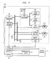
- FIG. 2 illustrates an apparatus for implementing the invention in a field environment.
- PBX 200 is providing telecommunication service for telephone sets 212 through 213.
- the telephone sets are connected to the switching network 202 via line circuits 208 through 209.
- line circuits 208 and 209 are connected to bus 214 and receive control information from PBX processor 201 via bus 214.
- PBX processor 201 provides the overall control for PBX 200.
- Remote maintenance printed circuit board 211 provides the remote maintenance capability on PBX 200 for maintenance center 217.
- maintenance center 217 accesses remote maintenance printed circuit board 211 via Internet 219, PBX processor 201, and bus 214. As is well known in the art, PBX processor 201 may also have access to Internet 219 through other computers. In addition, upon the failure of PBX processor 201, maintenance center 217 accesses remote maintenance printed circuit board 211 via public telephone network 218. In addition, public telephone network 218 provides access to other telephones for telephone sets 212 through 213 via switching network 202. Maintenance center 217 obtains the serial numbers for the printed circuit boards in PBX 200 from central database 111 via Internet 219 or public telephone net 218.
- maintenance center 217 requests via Internet 219 from PBX processor 201 the serial numbers of all printed circuit boards in PBX 200.
- PBX processor 201 obtains the serial number for each individual printed circuit board by performing the following operations with each printed circuit board. For example, PBX processor 201 requests from printed circuit board processor 204 the serial number for printed circuit board 102.
- Printed circuit board processor 204 accesses the locations where the serial number is stored in both flash memory 206 and 207.
- Printed circuit board processor 204 then transmits the serial number to PBX processor 201 which in turn relays it to maintenance center 217.
- Various encryption methods can also be utilized to encrypt the serial numbers stored in flash memories 206 and 207.
- FIG. 3 illustrates, in flowchart form, the steps performed by test set processor 108.
- block 302 activates the mechanism that causes bed of nails 104 to make contact with printed circuit board 102.
- Block 303 obtains the programs and data from central database 111, and block 304 loads the data and programs into the appropriate memories on printed circuit board 102.
- Block 306 requests that the operator of test set 101 use barcode scanner 109 to scan barcode 103 of printed circuit board 102.
- Decision block 307 waits until the operator has scanned the barcode before transferring control to block 308. The latter block reads the barcode from barcode scanner 101.
- Block 309 converts the barcode into the serial number of printed circuit board 102 and stores this in memories 206 and 207.
- serial numbers may be encrypted or otherwise made unintelligible to those trying to obtain the serial number from memories 206 and 207 utilizing techniques well known to those skilled in the art.
- the serial number is transmitted to central database 111.
- the operation is now completed by execution of block 312. Note, as is well known in the art, test set 101 also performs the necessary diagnostics to establish that printed circuit board 102 is functioning properly.
- FIG. 4 illustrates the operations performed by printed circuit board processor 204 of FIG. 2. Once started in block 401, decision block 402 waits for a request for the serial number stored in flash memories 206 and 207 from PBX processor 201.
- control is transferred to block 403 which performs normal processing for the functions of printed circuit board 102. If a request for a serial number is received, decision block 402 transfers control to block 404 that accesses the serial numbers from memories 206 and 207. Block 406 then analyzes the serial numbers. Block 406 decrypts the serial numbers if they are encrypted or otherwise protected from casual scrutiny. Once the necessary operations have been performed to extract the serial numbers in their correct form, the serial numbers are compared to make sure that they are the same by decision block 407. If the answer is no, block 408 performs error recovery before transferring control back to decision block 402. This error recovery would include informing PBX processor 201 of the failure.
- PBX processor 201 makes printed circuit board 102 non-operational and institutes a maintenance alarm. If the serial numbers are the same, decision block 407 transfers control to block 409 that transmits the resulting serial number to PBX processor 201 before transferring control back to decision block 402.
Landscapes
- Engineering & Computer Science (AREA)
- Theoretical Computer Science (AREA)
- Computer Hardware Design (AREA)
- General Engineering & Computer Science (AREA)
- Physics & Mathematics (AREA)
- General Physics & Mathematics (AREA)
- Quality & Reliability (AREA)
- Mathematical Physics (AREA)
- Computer Security & Cryptography (AREA)
- Software Systems (AREA)
- Computer Networks & Wireless Communication (AREA)
- Signal Processing (AREA)
- Test And Diagnosis Of Digital Computers (AREA)
- Monitoring And Testing Of Exchanges (AREA)
Abstract
Description
- This invention relates to protection of circuit identification information and more particularly, to an arrangement for protecting a serial number of a printed circuit board.
- A problem for companies who manufacture, sell, and service large electronic systems is to be able to identify on a customer site or at a repair facility individual printed circuit cards. Within the telecommunication industry, the cost of an individual printed circuit board is thousands of dollars. In addition, because of the global economy, a manufacturer may choose to sell the identical printed circuit board at a lower cost in a first country than in a second country. The so-called gray market is the practice of taking cards that are sold in the first country and shipping them to the second country. From a contractual point of view, this practice is not allowed, however it is difficult to prevent unless individual cards can be identified with a unique serial number.
- The second problem that manufacturers have with the more expensive and more complex cards is the necessity of being able to track individual cards for repair purposes. For example, most large system manufacturers maintain a data base that identifies each card produced by that manufacturer by a unique serial number. This serial number is utilized to identify problems that have been occurring on the printed circuit board and also to be able to know what vintage a particular type of printed circuit board is. Finally, manufacturers also offer service contracts for the maintenance of their systems. A large customer may choose to have a maintenance contract on one system but not on another system. The problem that occurs is that if the customer detects that a printed circuit board has failed in a system that does not have a maintenance contract, the customer may move the failed printed circuit board to the system that has the maintenance contract. Hence, even within a single country, it is necessary to be able to identify an individual printed circuit board to an individual system.
- The prior art has attempted to address these problems in a variety of ways. First, is to place the serial number of the card in printable form on the printed circuit board using a barcode or a human readable number. The problem with this solution is that individuals simply manufacture their own labels. Manufacturers have also attempted to mold or laser reproduce serial numbers into the face plates of printed circuit boards or on the printed circuit boards themselves. These techniques suffer from cost and also in the case of the face plates individuals simply remove the face plates and move it to another printed circuit board. A final solution is to utilize unique integrated circuits that have a preset number. Such an integrated circuit is placed on the printed circuit board in a manner in which it can be read externally by a device. The problem with this solution is that these devices are easily identified on a printed circuit board and can be removed and placed on another printed circuit board. In addition, the number is determined by the manufacturer of the integrated circuit and does not directly correspond with the actual serial number of the printed circuit board. In addition, there is the cost associated with the purchase and the installation of a unique integrated circuit on a printed circuit board for the sole purpose of identifying the board. One such device that has a pre-programmed identification number is the DS1990A manufactured by Dallas Semiconductor.
- The foregoing problems are solved and a technical advance is achieved by allowing a test set during the final testing of a printed circuit board to insert the actual serial number of the printed circuit board into one or more memory devices on the printed circuit board.
- Advantageously, the test set obtains the serial number of the printed circuit board by the utilization of scanner which scans the serial number from the barcode on the printed circuit board. Further, the barcode's serial number is uniquely identified by the manufacturer in the manufacturer's database. The test set inserts the serial information into one or more memory devices on the printed circuit board. Advantageously, the serial information is encrypted before being inserted into the memory devices. The serial number is then transmitted to the manufacturer's database where it is stored and associated with the telecommunication switching system that the printed circuit board will be inserted into. The central database in response to the serial information transmits operational information such as programs and data to the test set for insertion into the printed circuit board. After the printed circuit board has finished being tested on the test set, it is made operational in its assigned telecommunications switching system either at the manufacturer's location or in a field installation. During routine maintenance, a processor controlling the telecommunication switching system requests the serial number from the printed circuit board. A controller providing control of the printed circuit board decrypts the serial number and transmits it to the processor. The processor then transmits a request to the manufacturer's database to verify that the printed circuit board as identified by the serial number should be operational in this particular telecommunication switching system. This request can be made either by a direct telecommunication call or via the Internet. The manufacturer's database determines if the printed circuit board should or should not be operational in this particular telecommunication switching system. If the answer is yes, the card is allowed to remain operational. If the answer is no, the processor controlling the telecommunication switching system disables the printed circuit board and initiate a maintenance alarm. Advantageously, the checking to verify that the printed circuit board is operational in its assigned telecommunication switching system prevents the unauthorized use of the printed circuit board in other telecommunication switching systems.
- These and other features and advantages of the invention will become apparent from the following description of the illustrative embodiments of the invention considered together with the drawing.
-
- FIG. 1 illustrates in block diagram form, a system for implementing the invention during testing;
- FIG. 2 illustrates, in block form, a system for implementing the invention during field use;
- FIG. 3 illustrates, in flowchart form, the steps performed by a test set processor; and
- FIG. 4 illustrates, in flowchart form, the steps performed by printed circuit board processor.
-
- FIG. 1 illustrates the apparatus for implementing the invention.
Test set 101 is of a type well known in the art. An example of such a test set is the HP3070.Test set 101 establishes electrical contact with a printed circuit board such as printedcircuit board 102 via bed ofnails 104. Bed ofnails 104 has a plurality of small vertical electrical contact pins that establish electrical connections with various portions of printedcircuit board 102.Test set 101 is controlled by test setprocessor 108.User interface 107 allows an operator oftest set 101 to interface with test setprocessor 108. Test setprocessor 108 can receive and transmit signals to printedcircuit board 102 viainterface circuit 106 and bed ofnails 104. Barcodescanner 109 is utilized to scan the barcodes on printed circuit boards. As is well known in the art, test setprocessor 108 can exchange data withcentral database 111. - Printed
circuit board 102 has a large number of components designated ascomponents 112. As is illustrated in FIG. 2,components 112 includesflash memory 206,flash memory 207,line circuits 208 and printedcircuit board processor 204. Not illustrated in FIG. 1, printedcircuit board 102 has a connector of a well-known design that allows it to plug into a carrier within PBX 200 of FIG. 2. - Central
database 111 maintains a database for all printed circuit boards being manufactured or that have been manufactured by a particular manufacturer, and in which PBX, a printed circuit board is allowed to be operational.Central database 111 also contains the programs and operational data that must be loaded in to flashmemories circuit board 102, test set 101 requests the program and operational data fromcentral database 111. Test set 101 then inserts this data into the appropriate flash memories and other devices. Next, test setprocessor 108 instructs the operator to utilizebarcode scanner 109 to scanbarcode 103 that is affixed to printedcircuit board 102.Barcode 103 defines the unique serial number of printedcircuit board 102 that defines various attributes of the board to the manufacturer. In response to the serial number,test processor 108 transmits this tocentral database 111 and programs it intoflash memory flash memories Central database 111 then correlates printedcircuit board 102 with the serial number. Finally,test processor 108 performs a full functional test of printedcircuit board 102 to assure that printedcircuit board 102 is properly functioning. - FIG. 2 illustrates an apparatus for implementing the invention in a field environment.
PBX 200 is providing telecommunication service for telephone sets 212 through 213. The telephone sets are connected to theswitching network 202 vialine circuits 208 through 209. In addition,line circuits PBX processor 201 via bus 214.PBX processor 201 provides the overall control forPBX 200. Remote maintenance printedcircuit board 211 provides the remote maintenance capability onPBX 200 formaintenance center 217. - During normal operation,
maintenance center 217 accesses remote maintenance printedcircuit board 211 viaInternet 219,PBX processor 201, and bus 214. As is well known in the art,PBX processor 201 may also have access toInternet 219 through other computers. In addition, upon the failure ofPBX processor 201,maintenance center 217 accesses remote maintenance printedcircuit board 211 viapublic telephone network 218. In addition,public telephone network 218 provides access to other telephones for telephone sets 212 through 213 via switchingnetwork 202.Maintenance center 217 obtains the serial numbers for the printed circuit boards inPBX 200 fromcentral database 111 viaInternet 219 orpublic telephone net 218. Periodically,maintenance center 217 requests viaInternet 219 fromPBX processor 201 the serial numbers of all printed circuit boards inPBX 200. In response to this request frommaintenance center 217,PBX processor 201 obtains the serial number for each individual printed circuit board by performing the following operations with each printed circuit board. For example,PBX processor 201 requests from printedcircuit board processor 204 the serial number for printedcircuit board 102. Printedcircuit board processor 204 accesses the locations where the serial number is stored in bothflash memory circuit board processor 204 then transmits the serial number toPBX processor 201 which in turn relays it tomaintenance center 217. Various encryption methods can also be utilized to encrypt the serial numbers stored inflash memories - FIG. 3 illustrates, in flowchart form, the steps performed by test set
processor 108. After the program is started by the operator fromblock 301, block 302 activates the mechanism that causes bed ofnails 104 to make contact with printedcircuit board 102.Block 303 then obtains the programs and data fromcentral database 111, and block 304 loads the data and programs into the appropriate memories on printedcircuit board 102.Block 306 requests that the operator of test set 101use barcode scanner 109 to scanbarcode 103 of printedcircuit board 102.Decision block 307 waits until the operator has scanned the barcode before transferring control to block 308. The latter block reads the barcode frombarcode scanner 101.Block 309 converts the barcode into the serial number of printedcircuit board 102 and stores this inmemories memories circuit board 102, the serial number is transmitted tocentral database 111. The operation is now completed by execution ofblock 312. Note, as is well known in the art, test set 101 also performs the necessary diagnostics to establish that printedcircuit board 102 is functioning properly. FIG. 4 illustrates the operations performed by printedcircuit board processor 204 of FIG. 2. Once started inblock 401,decision block 402 waits for a request for the serial number stored inflash memories PBX processor 201. If a request is not received, control is transferred to block 403 which performs normal processing for the functions of printedcircuit board 102. If a request for a serial number is received,decision block 402 transfers control to block 404 that accesses the serial numbers frommemories Block 406 then analyzes the serial numbers.Block 406 decrypts the serial numbers if they are encrypted or otherwise protected from casual scrutiny. Once the necessary operations have been performed to extract the serial numbers in their correct form, the serial numbers are compared to make sure that they are the same bydecision block 407. If the answer is no, block 408 performs error recovery before transferring control back todecision block 402. This error recovery would include informingPBX processor 201 of the failure. In response,PBX processor 201 makes printedcircuit board 102 non-operational and institutes a maintenance alarm. If the serial numbers are the same,decision block 407 transfers control to block 409 that transmits the resulting serial number toPBX processor 201 before transferring control back todecision block 402.
Claims (8)
- A method for protecting product serial information in a printed circuit board, comprising the steps of:CHARACTERIZED BYreading the serial information by a test set using a scanner during final test of the printed circuit board;inserting the serial information into a plurality of memory devices on the printed circuit board by the test set;transmitting the serial information to a central database;storing serial information by central database;transmitting operational information from the central database to the test set;storing the operational information into printed circuit board by test set;initializing operational status of printed circuit board in a telecommunication switching system;requesting the serial information from the printed circuit board by a processor controlling the telecommunication switching system in which the printed circuit board is operational;transmitting the serial information to the processor by the printed circuit board;requesting by the processor that the central data base verify that the printed circuit board as identified by the serial information should be operational in the telecommunication switching system;determining that the printed circuit board should not be operational in the telecommunication switching system by the central database;transmitting the determination to the processor; andmaking the printed circuit board non-operational by the processor in response to the determination by the central database.
- The method of claim 1 wherein the step of inserting the serial information into the plurality of memories by the test set comprises the step of encrypting the serial information by a controller controlling the printed circuit board.
- The method of claim 2 wherein the step of transmitting serial information to the processor by the printed circuit board comprises the step of decrypting the serial information by the controller controlling the printed circuit board.
- The method of claim 3 further comprises the step of allowing the printed circuit board to remain operational upon the determination by the central data base indicating that the printed circuit board should be operational in the telecommunication switching system.
- An apparatus for protecting product serial information in a printed circuit board, comprising:CHARACTERIZED BYmeans for reading the serial information by a test set using a scanner during final test of the printed circuit board;means for inserting the serial information into a plurality of memory devices on the printed circuit board by the test set;means for transmitting the serial information to a central database;means for storing serial information by central database;means for transmitting operational information from the central database to the test set;means for storing the operational information into printed circuit board by test set;means for initializing operational status of printed circuit board in a telecommunication switching system;means for requesting the serial information from the printed circuit board by a processor controlling the telecommunication switching system in which the printed circuit board is operational;means for transmitting the serial information to the processor by the printed circuit board;means for requesting by the processor that the central data base verify that the printed circuit board as identified by the serial information should be operational in the telecommunication switching system;means for determining that the printed circuit board should not be operational in the telecommunication switching system by the central database;means for transmitting the determination to the processor; andmeans for making the printed circuit board non-operational by the processor in response to the determination by the central database.
- The apparatus of claim 5 wherein the means for inserting the serial information into the plurality of memories by the test set comprises means for encrypting the serial information by a controller controlling the printed circuit board.
- The apparatus of claim 6 wherein the step of transmitting serial information to the processor by the printed circuit board comprises means for decrypting the serial information by the controller controlling the printed circuit board.
- The apparatus of claim 7 further comprises means for allowing the printed circuit board to remain operational upon the determination by the central data base indicating that the printed circuit board should be operational in the telecommunication switching system.
Applications Claiming Priority (2)
| Application Number | Priority Date | Filing Date | Title |
|---|---|---|---|
| US629791 | 2000-07-31 | ||
| US09/629,791 US6629061B1 (en) | 2000-07-31 | 2000-07-31 | Automatic concealment of product serialization information |
Publications (2)
| Publication Number | Publication Date |
|---|---|
| EP1178406A1 true EP1178406A1 (en) | 2002-02-06 |
| EP1178406B1 EP1178406B1 (en) | 2003-03-12 |
Family
ID=24524502
Family Applications (1)
| Application Number | Title | Priority Date | Filing Date |
|---|---|---|---|
| EP01304051A Expired - Lifetime EP1178406B1 (en) | 2000-07-31 | 2001-05-03 | Automatic concealment of product serialization information |
Country Status (4)
| Country | Link |
|---|---|
| US (1) | US6629061B1 (en) |
| EP (1) | EP1178406B1 (en) |
| JP (1) | JP3723474B2 (en) |
| DE (1) | DE60100120T2 (en) |
Cited By (2)
| Publication number | Priority date | Publication date | Assignee | Title |
|---|---|---|---|---|
| EP1612637A1 (en) * | 2004-06-29 | 2006-01-04 | Nagracard S.A. | Security module and method of personalisation of a security module |
| NL1044044A (en) * | 2020-05-28 | 2021-12-01 | Sandgrain B V | Centralized handling of ic identification codes |
Families Citing this family (10)
| Publication number | Priority date | Publication date | Assignee | Title |
|---|---|---|---|---|
| JP4899248B2 (en) * | 2001-04-02 | 2012-03-21 | 富士通セミコンダクター株式会社 | Semiconductor integrated circuit |
| US20050210274A1 (en) * | 2004-03-22 | 2005-09-22 | Frantz Gene A | Apparatus and method for intellectual property protection using the microprocessor serial number |
| US20090249085A1 (en) * | 2004-06-29 | 2009-10-01 | Nagracard S.A. | Security module and personalization method for such a security module |
| EP2024899B1 (en) | 2005-09-05 | 2015-11-04 | Alpvision S.A. | Means for using microstructure of materials surface as a unique identifier |
| US9208394B2 (en) | 2005-09-05 | 2015-12-08 | Alpvision S.A. | Authentication of an article of manufacture using an image of the microstructure of it surface |
| US7845016B2 (en) * | 2005-11-28 | 2010-11-30 | Cisco Technology, Inc. | Methods and apparatus for verifying modules from approved vendors |
| US12094286B2 (en) | 2006-09-05 | 2024-09-17 | Alpvision S.A. | Means for using microstructure of materials surface as a unique identifier |
| US8769654B2 (en) * | 2009-06-23 | 2014-07-01 | Cisco Technology, Inc. | Counterfeit prevention strategy for pluggable modules |
| SG177597A1 (en) * | 2009-07-10 | 2012-03-29 | Certicom Corp | System and method for performing serialization of devices |
| CN106682912B (en) | 2015-11-10 | 2021-06-15 | 艾普维真股份有限公司 | Authentication method of 3D structure |
Citations (7)
| Publication number | Priority date | Publication date | Assignee | Title |
|---|---|---|---|---|
| US4456790A (en) * | 1982-02-08 | 1984-06-26 | Bell Telephone Laboratories, Incorporated | Automated hardware inventory system |
| EP0852349A2 (en) * | 1997-01-06 | 1998-07-08 | Isogon Corporation | Software license verification process and apparatus |
| WO1998043151A1 (en) * | 1997-03-24 | 1998-10-01 | Absolute Software Corporation | Method and apparatus to monitor and locate an electronic device using a secured intelligent agent via a global network |
| US5928328A (en) * | 1993-02-08 | 1999-07-27 | Honda Giken Kogyo Kabushikikaisha | Computer network management information system |
| US5959275A (en) * | 1997-03-25 | 1999-09-28 | Mci Communications Corporation | System and method for registering and maintaining field equipment inventory based on individualized equipment and location information |
| US6032257A (en) * | 1997-08-29 | 2000-02-29 | Compaq Computer Corporation | Hardware theft-protection architecture |
| EP1006447A2 (en) * | 1998-11-30 | 2000-06-07 | General Electric Company | Remote monitoring of electronic boards/software routines |
Family Cites Families (8)
| Publication number | Priority date | Publication date | Assignee | Title |
|---|---|---|---|---|
| US5796750A (en) * | 1994-04-22 | 1998-08-18 | Lattice Semiconductor Corporation | Method for programming a programmable logic device in an automatic tester |
| US5857021A (en) * | 1995-11-07 | 1999-01-05 | Fujitsu Ltd. | Security system for protecting information stored in portable storage media |
| US5774545A (en) * | 1996-03-28 | 1998-06-30 | Lucent Technologies Inc. | Method and apparatus for enhancing security in and discouraging theft of VLSI and ULSI devices |
| US5933620A (en) * | 1996-03-28 | 1999-08-03 | Advanced Micro Devices, Inc. | Method and apparatus for serializing microprocessor identification numbers |
| US5838793A (en) * | 1996-04-09 | 1998-11-17 | International Business Machines Corporation | Controlling movement of owned parts |
| US5892906A (en) * | 1996-07-19 | 1999-04-06 | Chou; Wayne W. | Apparatus and method for preventing theft of computer devices |
| US6167401A (en) * | 1998-02-09 | 2000-12-26 | Ciena Corporation | Manufacturing control network having a relational database |
| KR200215120Y1 (en) * | 1998-12-01 | 2001-03-02 | 윤종용 | Portable computer |
-
2000
- 2000-07-31 US US09/629,791 patent/US6629061B1/en not_active Expired - Fee Related
-
2001
- 2001-05-03 EP EP01304051A patent/EP1178406B1/en not_active Expired - Lifetime
- 2001-05-03 DE DE60100120T patent/DE60100120T2/en not_active Expired - Fee Related
- 2001-07-31 JP JP2001230716A patent/JP3723474B2/en not_active Expired - Fee Related
Patent Citations (7)
| Publication number | Priority date | Publication date | Assignee | Title |
|---|---|---|---|---|
| US4456790A (en) * | 1982-02-08 | 1984-06-26 | Bell Telephone Laboratories, Incorporated | Automated hardware inventory system |
| US5928328A (en) * | 1993-02-08 | 1999-07-27 | Honda Giken Kogyo Kabushikikaisha | Computer network management information system |
| EP0852349A2 (en) * | 1997-01-06 | 1998-07-08 | Isogon Corporation | Software license verification process and apparatus |
| WO1998043151A1 (en) * | 1997-03-24 | 1998-10-01 | Absolute Software Corporation | Method and apparatus to monitor and locate an electronic device using a secured intelligent agent via a global network |
| US5959275A (en) * | 1997-03-25 | 1999-09-28 | Mci Communications Corporation | System and method for registering and maintaining field equipment inventory based on individualized equipment and location information |
| US6032257A (en) * | 1997-08-29 | 2000-02-29 | Compaq Computer Corporation | Hardware theft-protection architecture |
| EP1006447A2 (en) * | 1998-11-30 | 2000-06-07 | General Electric Company | Remote monitoring of electronic boards/software routines |
Cited By (4)
| Publication number | Priority date | Publication date | Assignee | Title |
|---|---|---|---|---|
| EP1612637A1 (en) * | 2004-06-29 | 2006-01-04 | Nagracard S.A. | Security module and method of personalisation of a security module |
| WO2006000584A1 (en) * | 2004-06-29 | 2006-01-05 | Nagracard S.A. | Security module and method of customising one such module |
| NL1044044A (en) * | 2020-05-28 | 2021-12-01 | Sandgrain B V | Centralized handling of ic identification codes |
| WO2021240445A1 (en) * | 2020-05-28 | 2021-12-02 | Sandgrain B.V. | Centralized handling of ic identification codes |
Also Published As
| Publication number | Publication date |
|---|---|
| US6629061B1 (en) | 2003-09-30 |
| DE60100120D1 (en) | 2003-04-17 |
| JP3723474B2 (en) | 2005-12-07 |
| JP2002142019A (en) | 2002-05-17 |
| DE60100120T2 (en) | 2003-12-18 |
| EP1178406B1 (en) | 2003-03-12 |
Similar Documents
| Publication | Publication Date | Title |
|---|---|---|
| US6041229A (en) | Transferring information | |
| US5093862A (en) | Data carrier-controlled terminal in a data exchange system | |
| KR100596041B1 (en) | Method and system for managing certificate of electronic device for civil | |
| EP1178406B1 (en) | Automatic concealment of product serialization information | |
| US6704678B2 (en) | Method and apparatus for downloading correct software to an electrical hardware platform | |
| US20020138761A1 (en) | Authentication system | |
| US7152230B2 (en) | Storage media storing data related to smart card, smart card system and smart card application loading method | |
| JP3239083B2 (en) | How to access data on a microprocessor card | |
| EP0203066A1 (en) | Security and usage monitoring | |
| KR20100031641A (en) | Authentication information managing unit, authentication information managing program and method thereof, authentication unit, and authentication program and method thereof | |
| CN101140545B (en) | Advices processing device, external device and program | |
| JP2003535497A (en) | Cryptographically checkable identification method of physical units in public wireless telecommunications networks | |
| CN113764293A (en) | Chip-on-wafer method, apparatus, storage medium and electronic device | |
| CN109831782A (en) | A secure transmission verification method for electronic card information | |
| CN101931657A (en) | The counterfeit prevention strategy that is used for pluggable modules | |
| CN1350760A (en) | Device for protecting the initial utilization of a process/chip card | |
| CN112039664B (en) | Data communication method and system suitable for intelligent ammeter | |
| JP3248658B2 (en) | Maintenance system and remote maintenance system and remote maintenance system | |
| KR20000002671A (en) | Monitoring system and method of illegal software use using security system | |
| JPH09179828A (en) | Device for assigning user in computer network | |
| JP2002014737A (en) | Processing device, integrated circuit, and integrated circuit package | |
| CN111931885A (en) | Method and device for processing product logistics information | |
| KR101853544B1 (en) | Apparatus and method for controlling the line | |
| JP5386860B2 (en) | Payment system, payment processing apparatus, validity verification apparatus, validity verification request processing program, validity verification processing program, and validity verification method | |
| JP4073971B2 (en) | Method for checking the validity of an electric circuit device |
Legal Events
| Date | Code | Title | Description |
|---|---|---|---|
| PUAI | Public reference made under article 153(3) epc to a published international application that has entered the european phase |
Free format text: ORIGINAL CODE: 0009012 |
|
| 17P | Request for examination filed |
Effective date: 20010523 |
|
| AK | Designated contracting states |
Kind code of ref document: A1 Designated state(s): DE GB Kind code of ref document: A1 Designated state(s): AT BE CH CY DE DK ES FI FR GB GR IE IT LI LU MC NL PT SE TR |
|
| AX | Request for extension of the european patent |
Free format text: AL;LT;LV;MK;RO;SI |
|
| 17Q | First examination report despatched |
Effective date: 20020114 |
|
| GRAH | Despatch of communication of intention to grant a patent |
Free format text: ORIGINAL CODE: EPIDOS IGRA |
|
| AKX | Designation fees paid |
Free format text: DE GB |
|
| GRAH | Despatch of communication of intention to grant a patent |
Free format text: ORIGINAL CODE: EPIDOS IGRA |
|
| GRAA | (expected) grant |
Free format text: ORIGINAL CODE: 0009210 |
|
| AK | Designated contracting states |
Designated state(s): DE GB |
|
| REG | Reference to a national code |
Ref country code: GB Ref legal event code: FG4D |
|
| REG | Reference to a national code |
Ref country code: IE Ref legal event code: FG4D |
|
| REF | Corresponds to: |
Ref document number: 60100120 Country of ref document: DE Date of ref document: 20030417 Kind code of ref document: P |
|
| PLBE | No opposition filed within time limit |
Free format text: ORIGINAL CODE: 0009261 |
|
| STAA | Information on the status of an ep patent application or granted ep patent |
Free format text: STATUS: NO OPPOSITION FILED WITHIN TIME LIMIT |
|
| 26N | No opposition filed |
Effective date: 20031215 |
|
| REG | Reference to a national code |
Ref country code: IE Ref legal event code: MM4A |
|
| PGFP | Annual fee paid to national office [announced via postgrant information from national office to epo] |
Ref country code: DE Payment date: 20080508 Year of fee payment: 8 |
|
| PGFP | Annual fee paid to national office [announced via postgrant information from national office to epo] |
Ref country code: GB Payment date: 20080507 Year of fee payment: 8 |
|
| REG | Reference to a national code |
Ref country code: GB Ref legal event code: 732E Free format text: REGISTERED BETWEEN 20090430 AND 20090506 |
|
| GBPC | Gb: european patent ceased through non-payment of renewal fee |
Effective date: 20090503 |
|
| PG25 | Lapsed in a contracting state [announced via postgrant information from national office to epo] |
Ref country code: GB Free format text: LAPSE BECAUSE OF NON-PAYMENT OF DUE FEES Effective date: 20090503 |
|
| PG25 | Lapsed in a contracting state [announced via postgrant information from national office to epo] |
Ref country code: DE Free format text: LAPSE BECAUSE OF NON-PAYMENT OF DUE FEES Effective date: 20091201 |