EP1178342A2 - Buffer tube that results in easy access to and low attenuation of fibers disposed within buffer tube - Google Patents
Buffer tube that results in easy access to and low attenuation of fibers disposed within buffer tube Download PDFInfo
- Publication number
- EP1178342A2 EP1178342A2 EP01402045A EP01402045A EP1178342A2 EP 1178342 A2 EP1178342 A2 EP 1178342A2 EP 01402045 A EP01402045 A EP 01402045A EP 01402045 A EP01402045 A EP 01402045A EP 1178342 A2 EP1178342 A2 EP 1178342A2
- Authority
- EP
- European Patent Office
- Prior art keywords
- buffer tube
- ripcord
- stress risers
- tube
- buffer
- Prior art date
- Legal status (The legal status is an assumption and is not a legal conclusion. Google has not performed a legal analysis and makes no representation as to the accuracy of the status listed.)
- Granted
Links
Images




Classifications
-
- G—PHYSICS
- G02—OPTICS
- G02B—OPTICAL ELEMENTS, SYSTEMS OR APPARATUS
- G02B6/00—Light guides; Structural details of arrangements comprising light guides and other optical elements, e.g. couplings
- G02B6/44—Mechanical structures for providing tensile strength and external protection for fibres, e.g. optical transmission cables
- G02B6/4401—Optical cables
- G02B6/4429—Means specially adapted for strengthening or protecting the cables
- G02B6/443—Protective covering
- G02B6/4431—Protective covering with provision in the protective covering, e.g. weak line, for gaining access to one or more fibres, e.g. for branching or tapping
Definitions
- access tools such as a ring cut and slitter tools
- Tearing the buffer tube with a fingernail is also a technique used to gain access to the fiber.
- the tool or fingernail will perturb and cause attenuation to signals carried in live fibers or cause damage to the fiber coating.
- Such attenuation is on the order of 0.5 dB and higher.
- An additional concern is that during removal of the buffer tube, the ring cut or breaking away of the buffer tube, a fiber will become damaged or will break.
- a ripcord filament within the tube, or using specialized tools to slice open a section of the buffer tube.
- the rip filament may be embedded in the buffer tube or encased in the buffer tube and is discussed in an Alcatel patent by Harbort entitled "Optical Cable having at Least Two Separate Multiple-Fiber units each having its own Soft Plastic Envelope," U.S.P. 4,909,593.
- the following patents discuss different access tools used to slice sections of the buffer tube. These include "Monotube Optical Fiber Cable and Method of using the Same," U.S.P. 5,172,620, “Monotube Cable Fiber Access Tool," U.S.P.
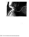
- FIG.2 An example of a conventional rip system is illustrated in Fig.2.
- a ripcord is being manipulated to tear through a buffer tube.
- a notch cannot be initiated in the buffer tube using the ripcord.
- the force required to create a notch with the ripcord is greater than the force to buckle the buffer tube.
- the rip system is clearly unstable as indicated by the significant curling and buckling of the fiber bundle on the righthand side of Fig. 1. This deformation of the fiber bundle contributes to the optical fiber damage and signal attenuation.
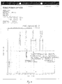
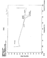
- the degree of buckling increases. Power loss measurements for the signal carried on an optical fiber disposed within the buffer tube of the conventional system are shown in Fig. 3.
- the present invention overcomes the above deficiencies of known buffer tubes and access techniques by providing a variety buffer tube designs that are strong enough to house fiber bundles together yet permits the fibers disposed within the tube to be accessed easily with minimal attenuation.
- the present buffer tube designs further mitigate the risk of fiber breakage, because no sharp cutting implements need to be used.
- the buffer tubes of the present invention are constructed from materials having an appropriate ratio between the energy needed to deform the buffer tube versus the energy needed to tear the buffer tube, with or without a ripcord, and how this relates to reduced attenuation.
- a primary feature of the invention comprises a ripcord disposed interior to the buffer tube or embedded in its wall. If a primary access method is used to open the buffer tube, the ripcord can be handled and used to promote a controlled tear in the buffer tube to allow access to several feet of fiber.
- the fracture energies of the buffer tube are selected so that the energy to pull the ripcord through the tube wall is less than the energy to bend the buffer tube bundle.
- the energy to yield of the ripcord should be greater than the energy to rip the ripcord through the buffer tube so that the ripcord does not break while attempting to remove the buffer tube.
- a second feature of the invention comprises a buffer tube with mechanical properties such that its energy to initiate a tear (e.g. energy to break) and propagate a tear are less than the energy needed to deform a fiber bundle. This reduces the chance of excessive attenuation to signals carried in the optical fibers.
- no primary access tools are required to initiate the tear in the buffer tube due to mechanical and material properties of the buffer tube.
- the ripcord need not be provided to propagate a tear.
- a third feature of the invention comprises a buffer tube with stress risers in the tube walls that promote a controlled fracture.
- the energy to fracture the buffer tube wall is low enough so that the fibers can be easily accessed or even lower such that it does not perturb the fiber bundle and does not cause significant attenuation to live fibers.
- the stress risers can be in the longitudinal direction parallel to the lay of the optic fibers, perpendicular to the fiber direction or in a spiral pattern.
- the stress risers can be either continually or intermittently formed in the buffer tube.
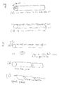
- a ripcord fiber or strands of fibers are laid parallel to the optical fiber bundle.
- the ripcord may be disposed interior to the buffer tube as shown in Fig. 4(a) or embedded in the tube wall as shown in Fig. 4(b).
- the ripcord(s) can be color coded or otherwise marked or banded to distinguish it from other components of the fiber bundle, such as the optical fibers.
- the ripcord fiber(s) can be used to open any desired length of the buffer tube with minimal deformation of the optical fiber bundle. This will occur if the following fracture mechanics criteria is met, that the energy to break the ripcord through the buffer tube or energy necessary to initiate and propagate a tear in the buffer tube is less than that needed to buckle the fiber bundle.
- Figs. 1-3 characterize a situation where this fracture condition is not met.
- the buckling of the conventional PVC buffer tube results since the energy that is required to cause the buckling is less than the energy required to break the ripcord through the buffer tube.
- the energy required to break the ripcord through the buffer tube is less than the energy required to buckle the bundle. If the energy needed to start a tear in the buffer tube by a ripcord is increased by using a thicker material or a more durable material (having a higher fracture initiation energy), the energy needed to buckle the buffer tube may be increased by increasing the viscosity of a gel disposed within the buffer tube or by using a cross-linked gel in order to meet the fracture condition.
- the energy to buckle the fiber bundle is lowered by using fewer fibers or by using a lower viscosity gel, the energy needed to initiate a tear would have to be reduced by using a thinner buffer tube material or using a material with a lower fracture initiation energy.
- the ripcord should be selected to have a high energy to yield compared with the energy needed to rip the cord through the buffer tube. This ensures that the ripcord will not break during the course of pulling the ripcord through the buffer tube.
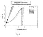
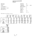
- the stress and energy characteristics for a ripcord according to a preferred embodiment are shown in Table 5.
- the corresponding load-displacement characteristics are shown in Fig. 6.
- the present buffer tube can be designed so that there are no special tools needed to open the tube.
- the tube has strong enough mechanical properties to hold the fiber bundle together, but can be easily torn using the fingers. This will more easily occur with materials that do not have a distinctive yield point and a high stress at break. Although, it can be obtained with materials that yield as long as they have a low elongation to break.
- the energy to tear is proportional to the energy to break divided by the stress at break squared. Changing the material properties so that there is a low energy to break relative to the stress at break decreases the effort needed to tear the material. This will allow finger access through the buffer tubes and allow long lengths of the buffer tube to be easily removed for a midspan or end access.
- the buffer tube material and thickness are such that the buffer tube can be peeled off from a fiber bundle with or without a ripcord filament. With the selection of material and thickness, pulling the tube laterally against a bundle of fibers is sufficient to cause the tube to split longitudinally.
- the use of a special cutting tool can also be obviated by selecting a material with a high coefficient of friction with skin, such that a ring cut in the buffer tube can be made by pulling the tube apart with the fingers.
- the tube material may have a high coefficient of friction with common materials such as rubber or paper, that is disposed against the buffer tube as a gripping layer to pull the tube apart with the fingers.
- Materials suitable for the buffer tube of the present invention include thermoplastics such as filled and blended polypropylene, polyolefins, EVA, EPA, PVC and ethyl acrylic acids.
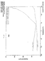
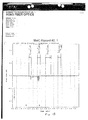
- Figs. 7(a)-7(b) illustrate empirical results for first and second heating of a buffer tube material according to the present invention.
- the data is shown for a material including a polyethylene and polypropylene copolymer blend.
- the troughs in the heat flow curve indicate the melting point of materials in the buffer tube.
- the second melting was performed after slow-cooling of the buffer tube material after the first heating.
- Fig. 8 shows the strain, energy and loading characteristics of the buffer tube material according to a preferred embodiment.
- Fig. 9 shows the corresponding stress-strain relationship.
- the energy to break the material should be larger than the energy to needed to initiate and/or propagate a tear in the material. It is estimated that the energy to break should be less than 1 Joule for a buffer tube that has a 1.4 mm outside diameter and a 1.0 mm inside diameter tested at 1 inch gage length. This results in a normalized energy to break the material of 52,000 kJ/m 3 .
- the stress-strain curve will have a steeper characteristic.
- the curve will take on a parabolic shape in the region of a low percent strain (e.g. less than 100) and will peak in the vicinity of several hundred percent strain (e.g. 250 to 800).
- the energy to break can be ascertained from the area disposed beneath the stress-strain curve.
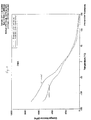
- Fig. 10 illustrates one example of the dynamic mechanical properties of the buffer tube material formed under air cooled and water cooled conditions.
- Fig. 10 shows the displacement of the buffer tube material as a function of temperature. It is observed that the air-cooled material exhibits more crystallinity and hence more dimensional stability than the water cooled material.
- Fig. 11 illustrates the stress of the material as a function of temperature. Again, the air-cooled buffer tube material exhibits greater crystallinity than the water-cooled structure.
- grooves or indents are continuously or sequentially incorporated in to the buffer tubes as stress risers to allow easier access to optical fibers by reducing the energy needed to tear into the buffer tube.
- the stress risers can be formed on an inner or outer surface of the buffer tube. Because the grooves and indentations include less material than other portions of the tube, proper groove depth selection will force a controlled fracture zone.
- Fig. 12(a) shows a continuously formed groove along the longitudinal direction of the buffer tube. An exemplary cross-section of the buffer tube having the groove is shown in Fig. 12(a)(1). Applicants have observed that a V-shaped cross section provides better results than a blunt shaped groove. The depth of the groove(s) will depend upon the type of material used.
- Fig. 12(b) illustrates sequentially formed stress risers perpendicular to the direction of the lay of the optical fibers.
- the spirals shaped grooves are more easily stressed than the longitudinal groove.
- the stress risers can be formed during buffer tube formation by using an appropriately molded die, or can be formed into the buffer tube after formation. The latter procedure would be especially applicable to more rigid materials.
- Abrading the exterior of the buffer tube with a material such as sandpaper is an additional technique that can be used to weaken the buffer tube.
- the tube will split along the abraded line when pulled laterally against the fiber bundle. Perforations may also be used to form the stress risers.
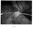
- Fig. 13 illustrates initiation of a tear in a buffer tube using manual manipulation according to embodiments of the invention. No special tools are required to initiate the tear in the buffer tube and gain access to the ripcord disposed therein.
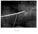
- Fig. 14 illustrates tearing of the buffer tube using the ripcord in a buffer tube design of the invention. Compared to Figs. 1-3 which included significant buckling and curling of the fiber bundle during the tearing process, Fig. 14 shows no significant deformation, thereby reducing the risk of fiber breakage or damage and reduced attenuation. Fig.
Landscapes
- Physics & Mathematics (AREA)
- General Physics & Mathematics (AREA)
- Optics & Photonics (AREA)
- Optical Fibers, Optical Fiber Cores, And Optical Fiber Bundles (AREA)
- Details Of Indoor Wiring (AREA)
- Instruments For Viewing The Inside Of Hollow Bodies (AREA)
- Light Guides In General And Applications Therefor (AREA)
- Rigid Pipes And Flexible Pipes (AREA)
- Insulated Conductors (AREA)
- Buffer Packaging (AREA)
- Glass Compositions (AREA)
- Surface Treatment Of Glass Fibres Or Filaments (AREA)
Abstract
Description
Claims (34)
- A buffer tube having a fiber bundle comprising one or more optical fibers disposed therein, said buffer tube having an energy to break threshold which is less than an energy necessary to deform the fiber bundle.
- The buffer tube of claim 1, wherein a ripcord is disposed interior to the buffer tube.
- The buffer tube of claim 2, wherein said ripcord has an energy to yield that is greater than an energy required to rip said ripcord through the buffer tube.
- The buffer tube of claim 3, wherein said ripcord is color coded to distinguish it from the fiber bundle.
- The buffer tube of claim 3, wherein said buffer tube is comprised with stress risers formed in a wall of said buffer tube.
- The buffer tube of claim 5, wherein said ripcord is color coded to distinguish it from the fiber bundle.
- The buffer tube of claim 5, wherein said stress risers include a groove also inventably formed on an inner surface of said wall of said buffer tube.
- The buffer tube of claim 5, wherein said stress risers are formed on an outer surface of said wall of said buffer tube.
- The buffer tube of claim 7, wherein said groove has a "V" shape.
- The buffer tube of claim 5, wherein said stress risers are formed in a longitudinal direction of said buffer tube.
- The buffer tube of claim 5, wherein said stress risers are formed in a perpendicular direction of said buffer tube.
- The buffer tube of claim 5, wherein said stress risers are in a spiral form around said buffer tube.
- The buffer tube of claim 1, wherein said buffer tube is comprised with stress risers formed in a wall of said buffer tube.
- The buffer tube of claim 13, wherein said stress risers include a groove also inventably formed on an inner surface of said wall of said buffer tube.
- The buffer tube of claim 13, wherein said stress risers are formed on an outer surface of said wall of said buffer tube.
- The buffer tube of claim 14, wherein said groove has a "V" shape.
- The buffer tube of claim 13, wherein said stress risers are formed in a longitudinal direction of said buffer tube.
- The buffer tube of claim 13, wherein said stress risers are formed in a perpendicular direction of said buffer tube.
- The buffer tube of claim 13, wherein said stress risers are in a spiral form around said buffer tube.
- A buffer tube having a fiber bundle comprising one or more optical fibers disposed therein, said buffer tube further comprising a ripcord disposed interior to said buffer tube having an energy to yield that is greater than an energy required to rip said ripcord through said buffer tube.
- The buffer tube of claim 20, wherein said ripcord is color coded to distinguish it from the fiber bundle.
- The buffer tube of claim 20, wherein said stress risers include a groove formed on an inner surface of said wall of said buffer tube.
- The buffer tube of claim 20, wherein said stress risers are formed on an outer surface of said wall of said buffer tube.
- The buffer tube of claim 22, wherein said groove has a "V" shape.
- The buffer tube of claim 20, wherein said stress risers are formed in a longitudinal direction of said buffer tube.
- The buffer tube of claim 20, wherein said stress risers are formed in a perpendicular direction of said buffer tube.
- The buffer tube of claim 20, wherein said stress risers are in a spiral form around said buffer tube.
- A buffer tube having a fiber bundle comprising one or more optical fibers disposed therein, said buffer tube further comprising stress risers formed in a wall of said buffer tube.
- The buffer tube of claim 28, wherein said stress risers include a groove also inventably formed on an inner surface of said wall of said buffer tube.
- The buffer tube of claim 28, wherein said stress risers are formed on an outer surface of said wall of said buffer tube.
- The buffer tube of claim 29, wherein said groove has a "V" shape.
- The buffer tube of claim 28, wherein said stress risers are formed in a longitudinal direction of said buffer tube.
- The buffer tube of claim 28, wherein said stress risers are formed in a perpendicular direction of said buffer tube.
- The buffer tube of claim 28, wherein said stress risers are in a spiral form around said buffer tube.
Applications Claiming Priority (4)
| Application Number | Priority Date | Filing Date | Title |
|---|---|---|---|
| US22292300P | 2000-08-04 | 2000-08-04 | |
| US222923 | 2000-08-04 | ||
| US892467 | 2001-06-28 | ||
| US09/892,467 US6603908B2 (en) | 2000-08-04 | 2001-06-28 | Buffer tube that results in easy access to and low attenuation of fibers disposed within buffer tube |
Publications (3)
| Publication Number | Publication Date |
|---|---|
| EP1178342A2 true EP1178342A2 (en) | 2002-02-06 |
| EP1178342A3 EP1178342A3 (en) | 2004-03-10 |
| EP1178342B1 EP1178342B1 (en) | 2008-02-27 |
Family
ID=26917274
Family Applications (1)
| Application Number | Title | Priority Date | Filing Date |
|---|---|---|---|
| EP01402045A Expired - Lifetime EP1178342B1 (en) | 2000-08-04 | 2001-07-27 | Buffer tube that results in easy access to and low attenuation of fibers disposed within buffer tube |
Country Status (5)
| Country | Link |
|---|---|
| US (1) | US6603908B2 (en) |
| EP (1) | EP1178342B1 (en) |
| AT (1) | ATE387640T1 (en) |
| DE (1) | DE60132958T2 (en) |
| ES (1) | ES2300310T3 (en) |
Cited By (1)
| Publication number | Priority date | Publication date | Assignee | Title |
|---|---|---|---|---|
| EP1406104A1 (en) * | 2002-10-01 | 2004-04-07 | Alcatel | Optical fiber cable having easy access tape with perforated, peelable sections |
Families Citing this family (119)
| Publication number | Priority date | Publication date | Assignee | Title |
|---|---|---|---|---|
| US6861590B2 (en) * | 2002-12-16 | 2005-03-01 | Alcatel | Strippable cable |
| US6876798B2 (en) * | 2003-08-29 | 2005-04-05 | Corning Cable Systems Llc | Fiber optic cable having a ripcord |
| US7197215B2 (en) * | 2004-12-15 | 2007-03-27 | Corning Cable Systems, Llc. | Fiber optic cables with easy access features |
| US8652782B2 (en) | 2006-09-12 | 2014-02-18 | Longhorn Vaccines & Diagnostics, Llc | Compositions and methods for detecting, identifying and quantitating mycobacterial-specific nucleic acids |
| US8097419B2 (en) | 2006-09-12 | 2012-01-17 | Longhorn Vaccines & Diagnostics Llc | Compositions and method for rapid, real-time detection of influenza A virus (H1N1) swine 2009 |
| US9481912B2 (en) | 2006-09-12 | 2016-11-01 | Longhorn Vaccines And Diagnostics, Llc | Compositions and methods for detecting and identifying nucleic acid sequences in biological samples |
| US8080645B2 (en) | 2007-10-01 | 2011-12-20 | Longhorn Vaccines & Diagnostics Llc | Biological specimen collection/transport compositions and methods |
| US11041215B2 (en) | 2007-08-24 | 2021-06-22 | Longhorn Vaccines And Diagnostics, Llc | PCR ready compositions and methods for detecting and identifying nucleic acid sequences |
| US9683256B2 (en) | 2007-10-01 | 2017-06-20 | Longhorn Vaccines And Diagnostics, Llc | Biological specimen collection and transport system |
| EP3058954B1 (en) * | 2007-08-27 | 2017-03-01 | Longhorn Vaccines and Diagnostics, LLC | Immunogenic compositions and methods |
| US10004799B2 (en) | 2007-08-27 | 2018-06-26 | Longhorn Vaccines And Diagnostics, Llc | Composite antigenic sequences and vaccines |
| DK2195466T3 (en) | 2007-10-01 | 2013-01-14 | Longhorn Vaccines & Diagnostics Llc | Method for storing biological samples |
| US11041216B2 (en) | 2007-10-01 | 2021-06-22 | Longhorn Vaccines And Diagnostics, Llc | Compositions and methods for detecting and quantifying nucleic acid sequences in blood samples |
| DK2206001T3 (en) * | 2007-11-09 | 2014-07-07 | Draka Comteq Bv | Optical fiber resistant to microbending |
| US8081853B2 (en) * | 2007-11-09 | 2011-12-20 | Draka Comteq, B.V. | Single-fiber drop cables for MDU deployments |
| US8041167B2 (en) * | 2007-11-09 | 2011-10-18 | Draka Comteq, B.V. | Optical-fiber loose tube cables |
| US8600206B2 (en) * | 2008-11-07 | 2013-12-03 | Draka Comteq, B.V. | Reduced-diameter optical fiber |
| US8041168B2 (en) * | 2007-11-09 | 2011-10-18 | Draka Comteq, B.V. | Reduced-diameter ribbon cables with high-performance optical fiber |
| US8031997B2 (en) * | 2007-11-09 | 2011-10-04 | Draka Comteq, B.V. | Reduced-diameter, easy-access loose tube cable |
| US8145026B2 (en) * | 2007-11-09 | 2012-03-27 | Draka Comteq, B.V. | Reduced-size flat drop cable |
| US8165439B2 (en) * | 2007-11-09 | 2012-04-24 | Draka Comteq, B.V. | ADSS cables with high-performance optical fiber |
| US8467650B2 (en) * | 2007-11-09 | 2013-06-18 | Draka Comteq, B.V. | High-fiber-density optical-fiber cable |
| FR2929716B1 (en) * | 2008-04-04 | 2011-09-16 | Draka Comteq France Sa | OPTICAL FIBER WITH DISPERSION OFFSET. |
| FR2930997B1 (en) | 2008-05-06 | 2010-08-13 | Draka Comteq France Sa | OPTICAL FIBER MONOMODE |
| FR2931253B1 (en) * | 2008-05-16 | 2010-08-20 | Draka Comteq France Sa | FIBER OPTIC TELECOMMUNICATION CABLE |
| FR2932932B1 (en) * | 2008-06-23 | 2010-08-13 | Draka Comteq France Sa | MULTIPLEX WAVE LENGTH OPTIC SYSTEM WITH MULTIMODE OPTIC FIBERS |
| FR2933779B1 (en) * | 2008-07-08 | 2010-08-27 | Draka Comteq France | MULTIMODE OPTIC FIBERS |
| US8257312B2 (en) * | 2008-07-30 | 2012-09-04 | Medtronic, Inc. | Integrated slitter for medical instrument inserter |
| US8007469B2 (en) * | 2008-07-30 | 2011-08-30 | Medtronic, Inc. | Medical instrument inserter |
| US7970247B2 (en) * | 2008-09-12 | 2011-06-28 | Draka Comteq B.V. | Buffer tubes for mid-span storage |
| FR2938389B1 (en) * | 2008-11-07 | 2011-04-15 | Draka Comteq France | MULTIMODE OPTICAL SYSTEM |
| DK2187486T3 (en) * | 2008-11-12 | 2014-07-07 | Draka Comteq Bv | Reinforcing optical fiber and method of manufacture |
| FR2939246B1 (en) * | 2008-12-02 | 2010-12-24 | Draka Comteq France | AMPLIFIER OPTICAL FIBER AND METHOD OF MANUFACTURE |
| FR2939522B1 (en) * | 2008-12-08 | 2011-02-11 | Draka Comteq France | OPTICAL FIBER AMPLIFIER RESISTANT TO IONIZING RADIATION |
| FR2939911B1 (en) * | 2008-12-12 | 2011-04-08 | Draka Comteq France | SOLDERED OPTICAL FIBER, TELECOMMUNICATION CABLE COMPRISING MULTIPLE OPTICAL FIBERS AND METHOD FOR MANUFACTURING SUCH A FIBER |
| NL1036343C2 (en) * | 2008-12-19 | 2010-06-22 | Draka Comteq Bv | METHOD AND APPARATUS FOR MANUFACTURING AN OPTICAL FORM. |
| EP2204681B1 (en) | 2008-12-30 | 2016-03-09 | Draka Comteq B.V. | Optical fibre cable comprising a perforated water-blocking element |
| WO2010077132A1 (en) | 2008-12-31 | 2010-07-08 | Draka Comteq B.V. | Uvled apparatus for curing glass-fiber coatings |
| FR2940839B1 (en) * | 2009-01-08 | 2012-09-14 | Draka Comteq France | INDEX GRADIENT MULTIMODAL OPTICAL FIBER, METHODS FOR CHARACTERIZATION AND MANUFACTURE OF SUCH A FIBER |
| FR2941539B1 (en) * | 2009-01-23 | 2011-02-25 | Draka Comteq France | OPTICAL FIBER MONOMODE |
| FR2941540B1 (en) * | 2009-01-27 | 2011-05-06 | Draka Comteq France | MONOMODE OPTICAL FIBER HAVING ENHANCED EFFECTIVE SURFACE |
| FR2941541B1 (en) * | 2009-01-27 | 2011-02-25 | Draka Comteq France | OPTICAL FIBER MONOMODE |
| US8489219B1 (en) | 2009-01-30 | 2013-07-16 | Draka Comteq B.V. | Process for making loose buffer tubes having controlled excess fiber length and reduced post-extrusion shrinkage |
| US9360647B2 (en) * | 2009-02-06 | 2016-06-07 | Draka Comteq, B.V. | Central-tube cable with high-conductivity conductors encapsulated with high-dielectric-strength insulation |
| FR2942571B1 (en) * | 2009-02-20 | 2011-02-25 | Draka Comteq France | AMPLIFIER OPTICAL FIBER COMPRISING NANOSTRUCTURES |
| FR2942551B1 (en) * | 2009-02-23 | 2011-07-15 | Draka Comteq France | CABLE COMPRISING ELEMENTS TO BE EXTRACTED, METHOD OF EXTRACTING THESE ELEMENTS AND METHOD OF MANUFACTURING THE SAME |
| US8625945B1 (en) | 2009-05-13 | 2014-01-07 | Draka Comteq, B.V. | Low-shrink reduced-diameter dry buffer tubes |
| US8625944B1 (en) | 2009-05-13 | 2014-01-07 | Draka Comteq, B.V. | Low-shrink reduced-diameter buffer tubes |
| FR2946436B1 (en) * | 2009-06-05 | 2011-12-09 | Draka Comteq France | MULTIMODE OPTICAL FIBER WITH LARGE BANDWIDTH WITH AN OPTIMIZED HEAT-SLEEVE INTERFACE |
| US20110026889A1 (en) * | 2009-07-31 | 2011-02-03 | Draka Comteq B.V. | Tight-Buffered Optical Fiber Unit Having Improved Accessibility |
| FR2953029B1 (en) * | 2009-11-25 | 2011-11-18 | Draka Comteq France | MULTIMODE OPTICAL FIBER WITH LARGE BANDWIDTH WITH AN OPTIMIZED HEAT-SLEEVE INTERFACE |
| FR2957153B1 (en) * | 2010-03-02 | 2012-08-10 | Draka Comteq France | MULTIMODE OPTICAL FIBER WITH BROAD BANDWIDTH AND LOW BENDBACK LOSSES |
| FR2953606B1 (en) * | 2009-12-03 | 2012-04-27 | Draka Comteq France | MULTIMODE OPTICAL FIBER WITH BROAD BANDWIDTH AND LOW BENDBACK LOSSES |
| FR2953030B1 (en) * | 2009-11-25 | 2011-11-18 | Draka Comteq France | MULTIMODE OPTICAL FIBER WITH LARGE BANDWIDTH WITH AN OPTIMIZED HEAT-SLEEVE INTERFACE |
| FR2953605B1 (en) * | 2009-12-03 | 2011-12-16 | Draka Comteq France | MULTIMODE OPTICAL FIBER WITH BROAD BANDWIDTH AND LOW BENDBACK LOSSES |
| US9014525B2 (en) | 2009-09-09 | 2015-04-21 | Draka Comteq, B.V. | Trench-assisted multimode optical fiber |
| FR2949870B1 (en) * | 2009-09-09 | 2011-12-16 | Draka Compteq France | MULTIMODE OPTICAL FIBER HAVING IMPROVED BENDING LOSSES |
| US8306380B2 (en) * | 2009-09-14 | 2012-11-06 | Draka Comteq, B.V. | Methods and devices for cable insertion into latched-duct conduit |
| FR2950156B1 (en) * | 2009-09-17 | 2011-11-18 | Draka Comteq France | MULTIMODE OPTIC FIBER |
| FR2950443B1 (en) * | 2009-09-22 | 2011-11-18 | Draka Comteq France | OPTICAL FIBER FOR SUM FREQUENCY GENERATION AND METHOD FOR MANUFACTURING THE SAME |
| US8805143B2 (en) * | 2009-10-19 | 2014-08-12 | Draka Comteq, B.V. | Optical-fiber cable having high fiber count and high fiber density |
| FR2952634B1 (en) * | 2009-11-13 | 2011-12-16 | Draka Comteq France | RARE EARTH DOPED SILICA FIBER WITH LOW DIGITAL OPENING |
| US9042693B2 (en) * | 2010-01-20 | 2015-05-26 | Draka Comteq, B.V. | Water-soluble water-blocking element |
| EP3399357B1 (en) * | 2010-02-01 | 2024-12-11 | Draka Comteq B.V. | Non-zero dispersion shifted optical fiber having a short cutoff wavelength |
| DK2352047T3 (en) * | 2010-02-01 | 2019-11-11 | Draka Comteq Bv | Non-zero dispersion-switched optical fiber with a large effective area |
| EP2369379B1 (en) * | 2010-03-17 | 2015-05-06 | Draka Comteq B.V. | Fibre optique monomode ayant des pertes par courbures réduites |
| US8693830B2 (en) | 2010-04-28 | 2014-04-08 | Draka Comteq, B.V. | Data-center cable |
| JP6017415B2 (en) | 2010-04-30 | 2016-11-02 | コーニング オプティカル コミュニケイションズ リミテッド ライアビリティ カンパニー | Optical fiber cable with access feature and method of manufacturing the same |
| PT2390700T (en) | 2010-05-03 | 2016-10-19 | Draka Comteq Bv | PACKAGED OPTICAL FIBER CABLES |
| DK2388239T3 (en) | 2010-05-20 | 2017-04-24 | Draka Comteq Bv | Curing apparatus using angled UV LEDs |
| US8625947B1 (en) | 2010-05-28 | 2014-01-07 | Draka Comteq, B.V. | Low-smoke and flame-retardant fiber optic cables |
| US8871311B2 (en) | 2010-06-03 | 2014-10-28 | Draka Comteq, B.V. | Curing method employing UV sources that emit differing ranges of UV radiation |
| FR2962230B1 (en) | 2010-07-02 | 2012-07-27 | Draka Comteq France | OPTICAL FIBER MONOMODE |
| US8682123B2 (en) | 2010-07-15 | 2014-03-25 | Draka Comteq, B.V. | Adhesively coupled optical fibers and enclosing tape |
| EP2418183B1 (en) | 2010-08-10 | 2018-07-25 | Draka Comteq B.V. | Method for curing coated glass fibres providing increased UVLED intensitiy |
| US8571369B2 (en) | 2010-09-03 | 2013-10-29 | Draka Comteq B.V. | Optical-fiber module having improved accessibility |
| US8565564B2 (en) | 2010-09-10 | 2013-10-22 | Prysmian Communications Cables And Systems Usa, Llc | Bundled optical fiber cable with grooved jacket |
| FR2966256B1 (en) | 2010-10-18 | 2012-11-16 | Draka Comteq France | MULTIMODE OPTICAL FIBER INSENSITIVE TO LOSSES BY |
| EP2633355B1 (en) | 2010-10-28 | 2020-07-15 | Corning Optical Communications LLC | Fiber optic cables with extruded access features and methods of making fiber optic cables |
| AU2011332930B2 (en) | 2010-11-23 | 2017-02-16 | Corning Optical Communications LLC | Fiber optic cables with access features |
| US8824845B1 (en) | 2010-12-03 | 2014-09-02 | Draka Comteq, B.V. | Buffer tubes having reduced stress whitening |
| DK2482106T5 (en) | 2011-01-31 | 2014-09-22 | Draka Comteq Bv | Multi-mode fiber |
| FR2971061B1 (en) | 2011-01-31 | 2013-02-08 | Draka Comteq France | BROAD BANDWIDTH OPTICAL FIBER WITH LOW CURB LOSSES |
| PT2678728T (en) | 2011-02-21 | 2018-07-05 | Draka Comteq Bv | Fiber Optic Interconnect Cable |
| EP2495589A1 (en) | 2011-03-04 | 2012-09-05 | Draka Comteq B.V. | Rare earth doped amplifying optical fiber for compact devices and method of manufacturing thereof |
| EP2503368A1 (en) | 2011-03-24 | 2012-09-26 | Draka Comteq B.V. | Multimode optical fiber with improved bend resistance |
| EP2506044A1 (en) | 2011-03-29 | 2012-10-03 | Draka Comteq B.V. | Multimode optical fiber |
| EP2518546B1 (en) | 2011-04-27 | 2018-06-20 | Draka Comteq B.V. | High-bandwidth, radiation-resistant multimode optical fiber |
| ES2438173T3 (en) | 2011-05-27 | 2014-01-16 | Draka Comteq Bv | Single mode fiber optic |
| EP2533082B1 (en) | 2011-06-09 | 2013-12-25 | Draka Comteq BV | Single mode optical fiber |
| DK2541292T3 (en) | 2011-07-01 | 2014-12-01 | Draka Comteq Bv | A multimode optical fiber |
| US8682124B2 (en) | 2011-10-13 | 2014-03-25 | Corning Cable Systems Llc | Access features of armored flat fiber optic cable |
| US9274302B2 (en) | 2011-10-13 | 2016-03-01 | Corning Cable Systems Llc | Fiber optic cables with extruded access features for access to a cable cavity |
| US9323022B2 (en) | 2012-10-08 | 2016-04-26 | Corning Cable Systems Llc | Methods of making and accessing cables having access features |
| EP2584340A1 (en) | 2011-10-20 | 2013-04-24 | Draka Comteq BV | Hydrogen sensing fiber and hydrogen sensor |
| US9201208B2 (en) | 2011-10-27 | 2015-12-01 | Corning Cable Systems Llc | Cable having core, jacket and polymeric jacket access features located in the jacket |
| US9176293B2 (en) | 2011-10-28 | 2015-11-03 | Corning Cable Systems Llc | Buffered fibers with access features |
| NL2007831C2 (en) | 2011-11-21 | 2013-05-23 | Draka Comteq Bv | Apparatus and method for carrying out a pcvd deposition process. |
| US9979168B2 (en) | 2011-12-01 | 2018-05-22 | Rockbestos Surprenant Cable Corp. | Perforation apparatus for cable jackets and related systems and methods |
| WO2013112916A1 (en) | 2012-01-26 | 2013-08-01 | Longhorn Vaccines And Diagnostics, Llc | Composite antigenic sequences and vaccines |
| US8929701B2 (en) | 2012-02-15 | 2015-01-06 | Draka Comteq, B.V. | Loose-tube optical-fiber cable |
| WO2013160714A1 (en) | 2012-04-27 | 2013-10-31 | Draka Comteq Bv | Hybrid single and multimode optical fiber for a home network |
| US8909014B2 (en) | 2012-04-27 | 2014-12-09 | Corning Cable Systems Llc | Fiber optic cable with access features and jacket-to-core coupling, and methods of making the same |
| US8620124B1 (en) | 2012-09-26 | 2013-12-31 | Corning Cable Systems Llc | Binder film for a fiber optic cable |
| US11287589B2 (en) | 2012-09-26 | 2022-03-29 | Corning Optical Communications LLC | Binder film for a fiber optic cable |
| US9091830B2 (en) | 2012-09-26 | 2015-07-28 | Corning Cable Systems Llc | Binder film for a fiber optic cable |
| NL2009684C2 (en) * | 2012-10-23 | 2014-04-29 | Draka Comteq Bv | An optical fiber cable. |
| US9188754B1 (en) | 2013-03-15 | 2015-11-17 | Draka Comteq, B.V. | Method for manufacturing an optical-fiber buffer tube |
| US9482839B2 (en) | 2013-08-09 | 2016-11-01 | Corning Cable Systems Llc | Optical fiber cable with anti-split feature |
| US8805144B1 (en) | 2013-09-24 | 2014-08-12 | Corning Optical Communications LLC | Stretchable fiber optic cable |
| US9075212B2 (en) | 2013-09-24 | 2015-07-07 | Corning Optical Communications LLC | Stretchable fiber optic cable |
| US8913862B1 (en) | 2013-09-27 | 2014-12-16 | Corning Optical Communications LLC | Optical communication cable |
| US9594226B2 (en) | 2013-10-18 | 2017-03-14 | Corning Optical Communications LLC | Optical fiber cable with reinforcement |
| US9976136B2 (en) | 2015-05-14 | 2018-05-22 | Longhorn Vaccines And Diagnostics, Llc | Rapid methods for the extraction of nucleic acids from biological samples |
| US10310209B2 (en) * | 2016-03-31 | 2019-06-04 | Ofs Fitel, Llc | Tight-buffered optical fiber having improved fiber access |
| US10748677B1 (en) * | 2019-07-09 | 2020-08-18 | Chris Lee Nelson | Signal transmission cable configurable for variable electromagnetic field emission |
| US11774694B2 (en) * | 2019-09-03 | 2023-10-03 | Corning Research & Development Corporation | Fiber carrying structure with rip cord and related method |
| US12485166B2 (en) | 2020-02-06 | 2025-12-02 | Longhorn Vaccines And Diagnostics, Llc | Vaccines for the treatment and prevention of zoonotic infections |
| WO2022087122A1 (en) | 2020-10-20 | 2022-04-28 | Longhorn Vaccines And Diagnostics, Llc | Immunogenic antigens |
Family Cites Families (19)
| Publication number | Priority date | Publication date | Assignee | Title |
|---|---|---|---|---|
| EP0020036B1 (en) | 1979-05-22 | 1982-08-11 | The Post Office | Improved communications cable |
| DE3564493D1 (en) | 1984-06-19 | 1988-09-22 | Telephone Cables Ltd | Optical fibre cables |
| JPS6249310A (en) * | 1985-08-29 | 1987-03-04 | Nippon Telegr & Teleph Corp <Ntt> | Optical fiber tube unit |
| US4815814A (en) | 1986-09-02 | 1989-03-28 | Cooper Industries, Inc. | Under-carpet flat cable assembly and method of forming a turn in same |
| US4729628A (en) | 1986-11-14 | 1988-03-08 | Siecor Corporation | Fiber optic dropwire |
| DE3743334C1 (en) | 1987-12-21 | 1989-05-24 | Standard Elektrik Lorenz Ag | Optical cable |
| US5013127A (en) * | 1990-04-26 | 1991-05-07 | Siecor Corporation | Flexible fiber optic distribution cable |
| US5067830A (en) | 1990-12-21 | 1991-11-26 | Siecor Corporation | Indented tube for optical ribbon |
| US5140751A (en) | 1991-06-11 | 1992-08-25 | Alcatel Na Cable Systems, Inc. | Monotube cable fiber access tool |
| US5172620A (en) | 1991-08-08 | 1992-12-22 | Alcatel Na Cable Systems, Inc. | Monotube optical fiber cable cutter and method of using the same |
| FR2693560A1 (en) * | 1992-07-10 | 1994-01-14 | Alcatel Cable | Cylindrical fibre=optic cable with fibres arranged around central core - binds fibres together in flexible resin which is then rolled up into cylindrical cable form incorporating cord to rip open resin to re-form ribbon |
| US5684910A (en) * | 1996-06-24 | 1997-11-04 | Lucent Technologies Inc. | Buffered optical fiber having a strippable buffer layer |
| FR2755769B1 (en) * | 1996-11-08 | 1998-12-31 | Telecommunications Sa | FIBER OPTIC TELECOMMUNICATION CABLE |
| JP3027961B2 (en) * | 1997-05-29 | 2000-04-04 | 住友電気工業株式会社 | Optical cable |
| US5970196A (en) | 1997-09-22 | 1999-10-19 | Siecor Corporation | Fiber optic protective member with removable section to facilitate separation thereof |
| DE19749930A1 (en) * | 1997-11-11 | 1999-05-12 | Siemens Ag | Optical microcable cutting and locating method for mounting technology |
| US6215931B1 (en) * | 1999-01-26 | 2001-04-10 | Alcatel | Flexible thermoplastic polyolefin elastomers for buffering transmission elements in a telecommunications cable |
| US6374023B1 (en) * | 1999-05-28 | 2002-04-16 | Corning Cable Systems Llc | Communication cable containing novel filling material in buffer tube |
| US6411403B1 (en) * | 2000-01-04 | 2002-06-25 | Fitel Usa Corp. | Polyamide/polyolefinfiber optic buffer tube material |
-
2001
- 2001-06-28 US US09/892,467 patent/US6603908B2/en not_active Expired - Lifetime
- 2001-07-27 ES ES01402045T patent/ES2300310T3/en not_active Expired - Lifetime
- 2001-07-27 EP EP01402045A patent/EP1178342B1/en not_active Expired - Lifetime
- 2001-07-27 DE DE60132958T patent/DE60132958T2/en not_active Expired - Lifetime
- 2001-07-27 AT AT01402045T patent/ATE387640T1/en not_active IP Right Cessation
Cited By (2)
| Publication number | Priority date | Publication date | Assignee | Title |
|---|---|---|---|---|
| EP1406104A1 (en) * | 2002-10-01 | 2004-04-07 | Alcatel | Optical fiber cable having easy access tape with perforated, peelable sections |
| US7050685B2 (en) | 2002-10-01 | 2006-05-23 | Alcatel | Cable easy access tape with perforated, peelable sections |
Also Published As
| Publication number | Publication date |
|---|---|
| DE60132958D1 (en) | 2008-04-10 |
| ES2300310T3 (en) | 2008-06-16 |
| ATE387640T1 (en) | 2008-03-15 |
| EP1178342A3 (en) | 2004-03-10 |
| DE60132958T2 (en) | 2009-02-19 |
| EP1178342B1 (en) | 2008-02-27 |
| US6603908B2 (en) | 2003-08-05 |
| US20030095763A1 (en) | 2003-05-22 |
Similar Documents
| Publication | Publication Date | Title |
|---|---|---|
| US6603908B2 (en) | Buffer tube that results in easy access to and low attenuation of fibers disposed within buffer tube | |
| CA1257996A (en) | Optical fibre cables | |
| US7817891B2 (en) | Method for accessing optical fibers within a telecommunication cable | |
| AU630221B2 (en) | Internally spiraled duct and method of installation | |
| US20090317039A1 (en) | Fiber optic cable having armor with easy access features | |
| WO2009110177A1 (en) | Optical fiber cable and method of mid-span access thereof | |
| GB1591129A (en) | Fibre-optic elements and their use | |
| AU2016201461A1 (en) | Fiber optic cables with extruded access features for access to a cable cavity | |
| US20250237841A1 (en) | Method of exposing core of optical fiber cable and optical fiber cable | |
| KR20230032891A (en) | Optical Cable | |
| US5604834A (en) | Method of midspan and/or end entry to access selected optical fibers within an optical ribbon fiber | |
| JP5260888B2 (en) | Slot rod for optical fiber cable and optical fiber cable using the same | |
| JP2010152086A (en) | Optical fiber cable | |
| US5460682A (en) | Method of midspan and/or end entry to access selected optical fibers within an optical ribbon fiber | |
| CA2591854A1 (en) | Main duct with inner duct and method for producing the same | |
| JP2005185049A (en) | Communication cable and protection tube for communication line | |
| CA2396668A1 (en) | Connector assemblies for fiber optic light cables and method of making same | |
| JP2021110820A (en) | Optical fiber cable | |
| EP2354823A1 (en) | A cutter tool and a method of making a branch connection with at least one optical fiber of a telecommunications cable | |
| US5531026A (en) | Stripping tool for armored fiber optic cables | |
| US20010029814A1 (en) | Fiber optic cable ripcord tool and method of use | |
| DK202170424A1 (en) | Improved high resolution headline sonar cable | |
| EP4501254B1 (en) | Mesh basket body and calculus removing mesh basket | |
| JP4094630B2 (en) | Single fiber separation method of optical fiber tape | |
| JP2007011018A (en) | Optical fiber cable and method for removing the outer jacket |
Legal Events
| Date | Code | Title | Description |
|---|---|---|---|
| PUAI | Public reference made under article 153(3) epc to a published international application that has entered the european phase |
Free format text: ORIGINAL CODE: 0009012 |
|
| AK | Designated contracting states |
Kind code of ref document: A2 Designated state(s): AT BE CH CY DE DK ES FI FR GB GR IE IT LI LU MC NL PT SE TR |
|
| AX | Request for extension of the european patent |
Free format text: AL;LT;LV;MK;RO;SI |
|
| RIN1 | Information on inventor provided before grant (corrected) |
Inventor name: BARKER, JEFF Inventor name: DALLAS, GEORGES JOHN Inventor name: WITT, GEOFF |
|
| PUAL | Search report despatched |
Free format text: ORIGINAL CODE: 0009013 |
|
| AK | Designated contracting states |
Kind code of ref document: A3 Designated state(s): AT BE CH CY DE DK ES FI FR GB GR IE IT LI LU MC NL PT SE TR |
|
| AX | Request for extension of the european patent |
Extension state: AL LT LV MK RO SI |
|
| 17P | Request for examination filed |
Effective date: 20040910 |
|
| AKX | Designation fees paid |
Designated state(s): AT BE CH CY DE DK ES FI FR GB GR IE IT LI LU MC NL PT SE TR |
|
| 17Q | First examination report despatched |
Effective date: 20041221 |
|
| RAP1 | Party data changed (applicant data changed or rights of an application transferred) |
Owner name: DRAKA COMTEQ B.V. |
|
| RAP1 | Party data changed (applicant data changed or rights of an application transferred) |
Owner name: DRAKA COMTEQ B.V. |
|
| RAP1 | Party data changed (applicant data changed or rights of an application transferred) |
Owner name: DRAKA COMTEQ B.V. |
|
| GRAP | Despatch of communication of intention to grant a patent |
Free format text: ORIGINAL CODE: EPIDOSNIGR1 |
|
| GRAS | Grant fee paid |
Free format text: ORIGINAL CODE: EPIDOSNIGR3 |
|
| GRAA | (expected) grant |
Free format text: ORIGINAL CODE: 0009210 |
|
| AK | Designated contracting states |
Kind code of ref document: B1 Designated state(s): AT BE CH CY DE DK ES FI FR GB GR IE IT LI LU MC NL PT SE TR |
|
| REG | Reference to a national code |
Ref country code: GB Ref legal event code: FG4D |
|
| REG | Reference to a national code |
Ref country code: CH Ref legal event code: EP |
|
| REG | Reference to a national code |
Ref country code: IE Ref legal event code: FG4D |
|
| REF | Corresponds to: |
Ref document number: 60132958 Country of ref document: DE Date of ref document: 20080410 Kind code of ref document: P |
|
| REG | Reference to a national code |
Ref country code: ES Ref legal event code: FG2A Ref document number: 2300310 Country of ref document: ES Kind code of ref document: T3 |
|
| PG25 | Lapsed in a contracting state [announced via postgrant information from national office to epo] |
Ref country code: FI Free format text: LAPSE BECAUSE OF FAILURE TO SUBMIT A TRANSLATION OF THE DESCRIPTION OR TO PAY THE FEE WITHIN THE PRESCRIBED TIME-LIMIT Effective date: 20080227 |
|
| NLV1 | Nl: lapsed or annulled due to failure to fulfill the requirements of art. 29p and 29m of the patents act | ||
| PG25 | Lapsed in a contracting state [announced via postgrant information from national office to epo] |
Ref country code: AT Free format text: LAPSE BECAUSE OF FAILURE TO SUBMIT A TRANSLATION OF THE DESCRIPTION OR TO PAY THE FEE WITHIN THE PRESCRIBED TIME-LIMIT Effective date: 20080227 |
|
| PG25 | Lapsed in a contracting state [announced via postgrant information from national office to epo] |
Ref country code: BE Free format text: LAPSE BECAUSE OF FAILURE TO SUBMIT A TRANSLATION OF THE DESCRIPTION OR TO PAY THE FEE WITHIN THE PRESCRIBED TIME-LIMIT Effective date: 20080227 |
|
| PG25 | Lapsed in a contracting state [announced via postgrant information from national office to epo] |
Ref country code: NL Free format text: LAPSE BECAUSE OF FAILURE TO SUBMIT A TRANSLATION OF THE DESCRIPTION OR TO PAY THE FEE WITHIN THE PRESCRIBED TIME-LIMIT Effective date: 20080227 Ref country code: DK Free format text: LAPSE BECAUSE OF FAILURE TO SUBMIT A TRANSLATION OF THE DESCRIPTION OR TO PAY THE FEE WITHIN THE PRESCRIBED TIME-LIMIT Effective date: 20080227 Ref country code: SE Free format text: LAPSE BECAUSE OF FAILURE TO SUBMIT A TRANSLATION OF THE DESCRIPTION OR TO PAY THE FEE WITHIN THE PRESCRIBED TIME-LIMIT Effective date: 20080527 Ref country code: PT Free format text: LAPSE BECAUSE OF FAILURE TO SUBMIT A TRANSLATION OF THE DESCRIPTION OR TO PAY THE FEE WITHIN THE PRESCRIBED TIME-LIMIT Effective date: 20080721 |
|
| ET | Fr: translation filed | ||
| PLBE | No opposition filed within time limit |
Free format text: ORIGINAL CODE: 0009261 |
|
| STAA | Information on the status of an ep patent application or granted ep patent |
Free format text: STATUS: NO OPPOSITION FILED WITHIN TIME LIMIT |
|
| 26N | No opposition filed |
Effective date: 20081128 |
|
| REG | Reference to a national code |
Ref country code: CH Ref legal event code: PL |
|
| GBPC | Gb: european patent ceased through non-payment of renewal fee |
Effective date: 20080727 |
|
| PG25 | Lapsed in a contracting state [announced via postgrant information from national office to epo] |
Ref country code: MC Free format text: LAPSE BECAUSE OF NON-PAYMENT OF DUE FEES Effective date: 20080731 |
|
| PG25 | Lapsed in a contracting state [announced via postgrant information from national office to epo] |
Ref country code: GB Free format text: LAPSE BECAUSE OF NON-PAYMENT OF DUE FEES Effective date: 20080727 Ref country code: LI Free format text: LAPSE BECAUSE OF NON-PAYMENT OF DUE FEES Effective date: 20080731 Ref country code: CH Free format text: LAPSE BECAUSE OF NON-PAYMENT OF DUE FEES Effective date: 20080731 |
|
| PG25 | Lapsed in a contracting state [announced via postgrant information from national office to epo] |
Ref country code: CY Free format text: LAPSE BECAUSE OF FAILURE TO SUBMIT A TRANSLATION OF THE DESCRIPTION OR TO PAY THE FEE WITHIN THE PRESCRIBED TIME-LIMIT Effective date: 20080227 Ref country code: IE Free format text: LAPSE BECAUSE OF NON-PAYMENT OF DUE FEES Effective date: 20080728 |
|
| PG25 | Lapsed in a contracting state [announced via postgrant information from national office to epo] |
Ref country code: LU Free format text: LAPSE BECAUSE OF NON-PAYMENT OF DUE FEES Effective date: 20080727 |
|
| PG25 | Lapsed in a contracting state [announced via postgrant information from national office to epo] |
Ref country code: TR Free format text: LAPSE BECAUSE OF FAILURE TO SUBMIT A TRANSLATION OF THE DESCRIPTION OR TO PAY THE FEE WITHIN THE PRESCRIBED TIME-LIMIT Effective date: 20080227 |
|
| PG25 | Lapsed in a contracting state [announced via postgrant information from national office to epo] |
Ref country code: GR Free format text: LAPSE BECAUSE OF FAILURE TO SUBMIT A TRANSLATION OF THE DESCRIPTION OR TO PAY THE FEE WITHIN THE PRESCRIBED TIME-LIMIT Effective date: 20080528 |
|
| REG | Reference to a national code |
Ref country code: FR Ref legal event code: PLFP Year of fee payment: 16 |
|
| REG | Reference to a national code |
Ref country code: FR Ref legal event code: PLFP Year of fee payment: 17 |
|
| REG | Reference to a national code |
Ref country code: FR Ref legal event code: PLFP Year of fee payment: 18 |
|
| PGFP | Annual fee paid to national office [announced via postgrant information from national office to epo] |
Ref country code: IT Payment date: 20190726 Year of fee payment: 19 Ref country code: ES Payment date: 20190801 Year of fee payment: 19 Ref country code: FR Payment date: 20190726 Year of fee payment: 19 Ref country code: DE Payment date: 20190729 Year of fee payment: 19 |
|
| REG | Reference to a national code |
Ref country code: DE Ref legal event code: R119 Ref document number: 60132958 Country of ref document: DE |
|
| PG25 | Lapsed in a contracting state [announced via postgrant information from national office to epo] |
Ref country code: FR Free format text: LAPSE BECAUSE OF NON-PAYMENT OF DUE FEES Effective date: 20200731 |
|
| PG25 | Lapsed in a contracting state [announced via postgrant information from national office to epo] |
Ref country code: DE Free format text: LAPSE BECAUSE OF NON-PAYMENT OF DUE FEES Effective date: 20210202 |
|
| REG | Reference to a national code |
Ref country code: ES Ref legal event code: FD2A Effective date: 20211207 |
|
| PG25 | Lapsed in a contracting state [announced via postgrant information from national office to epo] |
Ref country code: ES Free format text: LAPSE BECAUSE OF NON-PAYMENT OF DUE FEES Effective date: 20200728 |
|
| PG25 | Lapsed in a contracting state [announced via postgrant information from national office to epo] |
Ref country code: IT Free format text: LAPSE BECAUSE OF NON-PAYMENT OF DUE FEES Effective date: 20200727 |