EP1178338B1 - Parallel data transmission through segmented waveguides of large diameter - Google Patents
Parallel data transmission through segmented waveguides of large diameter Download PDFInfo
- Publication number
- EP1178338B1 EP1178338B1 EP01118069A EP01118069A EP1178338B1 EP 1178338 B1 EP1178338 B1 EP 1178338B1 EP 01118069 A EP01118069 A EP 01118069A EP 01118069 A EP01118069 A EP 01118069A EP 1178338 B1 EP1178338 B1 EP 1178338B1
- Authority
- EP
- European Patent Office
- Prior art keywords
- optical
- rotary joint
- transmitters
- fiber optic
- waveguide
- Prior art date
- Legal status (The legal status is an assumption and is not a legal conclusion. Google has not performed a legal analysis and makes no representation as to the accuracy of the status listed.)
- Expired - Lifetime
Links
- 230000005540 biological transmission Effects 0.000 title claims description 5
- 230000003287 optical effect Effects 0.000 claims abstract description 59
- 239000000835 fiber Substances 0.000 claims abstract description 55
- 238000000034 method Methods 0.000 claims description 11
- 101001028732 Chironex fleckeri Toxin CfTX-A Proteins 0.000 claims description 7
- 101001028722 Chironex fleckeri Toxin CfTX-B Proteins 0.000 claims description 7
- 230000003139 buffering effect Effects 0.000 claims 1
- 230000000712 assembly Effects 0.000 description 4
- 238000000429 assembly Methods 0.000 description 4
- 239000000872 buffer Substances 0.000 description 4
- 230000008054 signal transmission Effects 0.000 description 4
- 241000282326 Felis catus Species 0.000 description 2
- 238000010586 diagram Methods 0.000 description 1
- 238000009792 diffusion process Methods 0.000 description 1
- 238000012986 modification Methods 0.000 description 1
- 230000004048 modification Effects 0.000 description 1
- 238000006467 substitution reaction Methods 0.000 description 1
- 238000003325 tomography Methods 0.000 description 1
Images


Classifications
-
- H—ELECTRICITY
- H04—ELECTRIC COMMUNICATION TECHNIQUE
- H04Q—SELECTING
- H04Q11/00—Selecting arrangements for multiplex systems
- H04Q11/0001—Selecting arrangements for multiplex systems using optical switching
- H04Q11/0005—Switch and router aspects
-
- G—PHYSICS
- G02—OPTICS
- G02B—OPTICAL ELEMENTS, SYSTEMS OR APPARATUS
- G02B6/00—Light guides; Structural details of arrangements comprising light guides and other optical elements, e.g. couplings
- G02B6/24—Coupling light guides
- G02B6/36—Mechanical coupling means
- G02B6/3604—Rotary joints allowing relative rotational movement between opposing fibre or fibre bundle ends
-
- H—ELECTRICITY
- H04—ELECTRIC COMMUNICATION TECHNIQUE
- H04B—TRANSMISSION
- H04B10/00—Transmission systems employing electromagnetic waves other than radio-waves, e.g. infrared, visible or ultraviolet light, or employing corpuscular radiation, e.g. quantum communication
- H04B10/80—Optical aspects relating to the use of optical transmission for specific applications, not provided for in groups H04B10/03 - H04B10/70, e.g. optical power feeding or optical transmission through water
- H04B10/801—Optical aspects relating to the use of optical transmission for specific applications, not provided for in groups H04B10/03 - H04B10/70, e.g. optical power feeding or optical transmission through water using optical interconnects, e.g. light coupled isolators, circuit board interconnections
-
- H—ELECTRICITY
- H04—ELECTRIC COMMUNICATION TECHNIQUE
- H04Q—SELECTING
- H04Q11/00—Selecting arrangements for multiplex systems
- H04Q11/0001—Selecting arrangements for multiplex systems using optical switching
- H04Q11/0005—Switch and router aspects
- H04Q2011/0007—Construction
- H04Q2011/0024—Construction using space switching
Definitions
- the present invention relates generally to fiber optic rotary joints, and more particularly, to a fiber optic rotary joint that can receive multiple different signals during rotation of the rotor. Even more particularly, the present application relates to parallel data transmission through segmented waveguides of large diameter.
- the patent application entitled "Sectional Waveguides for Large Diameter Fiber Optic Rotary Joint” describes an example of a fiber optic rotary joint having eight source fibers (of equal length, 45° spacing), two sectional waveguides (22.5° in length, 55° spacing) and two pickup fibers (of equal length, positioned at ends of a respective waveguide).
- the same modulated light source is applied to each of the eight source fibers and is received by the two pickup fibers, and recovered through summation of the light output from the two pickup fibers.
- the described configuration minimizes the difference in propagation delay between the signals, which reduces pulse distortion and jitter when the optical signals are summed.
- WO 99/01850 discloses a signal transmitter and a method for transmitting data through one or several data channels between a rotating system and a stationary system.
- several transmitters LEDs
- one or more receivers photodiodes
- the transmitters and receivers are respectively arranged in ring-shaped areas and distributed in a homogeneous manner, so that each transmitter faces each receiver, when a full rotation of the rotating system occurs.
- a transmitters switching device allocates the data channels, to the respective transmitters facing specific receivers in a specific rotational angle arena according to a signal from a rotational angle sensor.
- WO 99/01720 filed on the same date by the same applicant as WO 99/01850 . teaches a sensor for angles of rotation in a similar context.
- US-A-5121419 discloses a computer-aided tomography apparatus having a rotor and a stator. It also comprises two lateral diffusion light guides wound round the rotor to transmit signals optically between a laser diode of the rotor and corresponding optical means of the stator. The device permits simultaneous transmission of data in parallel.
- Yet a further object of the present invention is to transmit up to eight separate channels of information across a fiber optic rotary joint.
- Still a further object of the present invention is to transmit eight individual data streams or an eight byte parallel data stream through the fiber optic rotary joint
- the objects are solved according to claim 1 by a fiber optic rotary joint and according to claim 7 by a method of transmitting multiple optical signals through a fiber optic rotary joint.
- the present invention is directed to a fiber optic rotary joint comprised of multiple segmented waveguides.
- Each of the multiple segmented waveguides is located on the stator.
- the segmented waveguides are circumferentially spaced from each other. Spaces between the segmented waveguides are non-reflective.
- Each of the segmented waveguides has an optical pickup.
- the present invention transmits eight individual serial data streams or an eight bit parallel word data stream through the large fiber optic rotary joint 100.
- an encoder or resolver By using an encoder or resolver, the position of each source fiber relative to the eight waveguides can be determined to a very high degree of accuracy.
- the information generated by the encoder or resolver will feed a high speed-switching network.
- the eight individual channels of data or one eight-bit parallel channel are fed into the switcher.
- the switcher is used to route the input data to the appropriate source fiber such that continuity is maintained between a specific input channel and a specific waveguide/pickup fiber receiver
- a fiber optic rotary joint including a plurality of optical waveguide segments attachable to a stator. Each of the optical waveguide segments has an optical pickup.
- a plurality of optical transmitters is located on a rotor and rotatable therewith.
- a position determining device determines a circumferential location of at least one of the plurality of optical transmitters during rotation thereof.
- a switch routes optical signals to be transmitted by the plurality of optical transmitters to be received by a predetermined one of the optical pickups.
- each of the segmented waveguide segments has an associated optical receiver and a plurality of optical transmitters on a rotor.
- a position is determined for each of the plurality of optical transmitters during rotation of the rotor. Based upon the position of the plurality of optical transmitters, each of the multiple optical signals is routed to a predetermined one of the segmented waveguides.
- the fiber optic rotary joint includes a stator 102 and a rotor 104.
- the fiber optic rotary joint 100 includes eight receivers RX 0, RX 1 ... RX 7, each on a segmented waveguide assembly 110, 120, 130 ... 180, each of which has a corresponding annular reflective surface 112, 122, 132 ... 182, respectively.
- Each of the segmented waveguide assemblies 110-180 is of short choral length and extends for approximately 22.5° and has the receiver RX 0, RX 1 ... RX 7, respectively, positioned at one end thereof.
- Each of the segmented waveguide assemblies 110 is attached to the stator 102.
- each of the receivers Rx 0, RX 1 ... RX 7 is located at the most counterclockwise position for each of the segmented waveguide assemblies 110-180.
- Each of the segmented waveguides 110-180 is equally circumferentially spaced and there is a gap or area of the existing gantry that is not actively being used for signal transmission.
- the inactive areas are non-reflective and absorb the transmitted optical signals. For example, there are gaps between segmented waveguide assemblies 110 and 120; between 120 and 130; between 130 and 140; between 140 and 150; between 150 and 160; between 160 and 170; between 170 and 180; and between 180 and 110.
- TX A As depicted in Figure 2 , there are sixteen transmitters TX A, TX B, TX C . .. TX P which are equally circumferentially spaced on the periphery of the rotor 104.
- receiver RX 0 will receive an optical signal from transmitter TX A
- receiver RX 1 will receive an optical signal from transmitter TX C
- transmitter TX B will be transmitting a signal received by receiver RX 0
- transmitter TX D will be receiving a signal received by receiver RX 1.
- the present invention can advantageously utilize the inactive areas of the ring (depicted in Figure 1 ) by using additional sections of waveguide 110-180 with their corresponding pickup fibers RX 0, RX 1 ... RX 7.
- FIG 2 there are eight sectional waveguides 110-180 (22.5° in length, 22.5° spacing), 16 source fibers TX 0, TX 1 ... TX P (of equal length, 22.5° spacing), and eight pickup fibers RX 0, RX 1 ... RX 7 (of equal length, positioned at ends of waveguide).
- each of the sixteen source fibers TX 0-TX P can transmit the same modulated light source, meaning all eight pickup fibers RX 0 - RX 7 receive the same signal from the same modulated light source. This feature would allow for certain combinations of redundancy in the system and would reduce the amount of optical power required for a particular BER.
- the received signal could be summed from all of the received signals.
- each waveguide 112-182 and pickup fiber assembly 110-180 treats each waveguide 112-182 and pickup fiber assembly 110-180 as an individual receiver. Rather than transmitting a single serial data stream through the large fiber optic rotary joint 100 which is limited to the maximum data rate of the sectional waveguide 110-180, the present invention transmits eight individual serial data streams or an eight bit parallel word data stream through the large fiber optic rotary joint 100.
- an encoder or resolver Figure 3
- the position of each source fiber TX 0-TX P relative to the eight waveguides 110-180 can be determined to a very high degree of accuracy.
- the encoder or resolver signal can be generated be an existing encoder or resolver which is part of the drive mechanism for rotating the rotor in a cat scan machine. If the present invention is used in a device that does not already have an encoder or resolver then one will be provided.
- the information generated by the encoder or resolver 204 will feed a high speed-switching network 202 ("switcher").
- the eight individual channels of data or one eight-bit parallel channel are fed into the switcher 202.
- the eight individual channels or one eight-bit parallel channel are described in conjunction with a 40 inch diameter ring. Of course, it should be appreciated that other numbers of channels or bits may be used depending upon various considerations including ring diameter, data rate, etc.
- the switcher 202 is used to route the input data to the appropriate source fiber TX 0-TX P such that continuity is maintained between a specific input channel and a specific waveguide/pickup fiber receiver RX 0-RX 7.
- Table 1 below shows the degree location, in this example, for turning the transmitter on and off with respect to the input data.
- the eight-bit input is connected to the input buffer BUF[0..7].
- the contents of the input buffer BUF [0..7] are connected to the switcher 202 whose control signals are generated by the information from the resolver/encoder 204.
- the switcher 202 routes the contents of:
Landscapes
- Physics & Mathematics (AREA)
- Engineering & Computer Science (AREA)
- Computer Networks & Wireless Communication (AREA)
- Signal Processing (AREA)
- Optics & Photonics (AREA)
- Electromagnetism (AREA)
- General Physics & Mathematics (AREA)
- Optical Couplings Of Light Guides (AREA)
- Arrangements For Transmission Of Measured Signals (AREA)
- Mechanical Coupling Of Light Guides (AREA)
- Mechanical Light Control Or Optical Switches (AREA)
- Waveguide Connection Structure (AREA)
- Waveguides (AREA)
- Apparatus For Radiation Diagnosis (AREA)
Abstract
Description
- The present application is related to a patent application entitled "Segmented Waveguide for Large Diameter Fiber Optic Rotary Joint", filed on even date herewith, and is related to
U.S. Patent Application Serial No. 09/531,772, filed March 21, 2000 - The present application also relates to
U.S. Patent No. 5,991,478, issued November 23, 1999 entitled "Fiber Optic Rotary Joint", andU.S. Patent Application Serial No. 09/115,946, filed July 15, 1998 - The present invention relates generally to fiber optic rotary joints, and more particularly, to a fiber optic rotary joint that can receive multiple different signals during rotation of the rotor. Even more particularly, the present application relates to parallel data transmission through segmented waveguides of large diameter.
- The patent application entitled "Sectional Waveguides for Large Diameter Fiber Optic Rotary Joint" describes an example of a fiber optic rotary joint having eight source fibers (of equal length, 45° spacing), two sectional waveguides (22.5° in length, 55° spacing) and two pickup fibers (of equal length, positioned at ends of a respective waveguide). The same modulated light source is applied to each of the eight source fibers and is received by the two pickup fibers, and recovered through summation of the light output from the two pickup fibers. The described configuration minimizes the difference in propagation delay between the signals, which reduces pulse distortion and jitter when the optical signals are summed. The reduction in pulse distortion and jitter allows for higher data rates to be transmitted through the fiber optic rotary joint than is possible with a continuous waveguide. Referring now to
Figure 1 , sufficient optical power necessary must be maintained to achieve a specified bit error rate (BER) with the arrangement illustrated inFigure 1 . For example, the same BER performance as disclosed in the patent application entitled "Sectional Waveguides for Large Diameter Fiber Optic Rotary Joint" can be achieved with a single short section of waveguide with one pickup fiber (RX 0). However, a single short section of waveguide with one pickup fiber (RX 0) will require 16 sources (TX A, TX B. . . TX P) to maintain the optical power level for a specified BER. As depicted inFigure 1 , only 22.5° of the 360° ring is actively being used for signal transmission. - Thus, a need exists in the art for a segmented waveguide that utilizes a large portion of the ring for signal transmission. Another need exists for a segmented waveguide which can handle multiple individual data streams.
- In addition to the teachings of the aforementioned, related applications, further information pertaining to the prior art can be found in
WO 99/01850 -
WO 99/01720 WO 99/01850 -
US-A-5121419 discloses a computer-aided tomography apparatus having a rotor and a stator. It also comprises two lateral diffusion light guides wound round the rotor to transmit signals optically between a laser diode of the rotor and corresponding optical means of the stator. The device permits simultaneous transmission of data in parallel. - A similar system is disclosed in
US-A-5134639 . - It is, therefore, an object of the present invention to utilize a large portion of the ring diameter for signal transmission.
- It is another object of the present invention to increase the data rate that can be transmitted through the fiber optic rotary joint.
- Yet a further object of the present invention is to transmit up to eight separate channels of information across a fiber optic rotary joint.
- Still a further object of the present invention is to transmit eight individual data streams or an eight byte parallel data stream through the fiber optic rotary joint
- The objects are solved according to
claim 1 by a fiber optic rotary joint and according toclaim 7 by a method of transmitting multiple optical signals through a fiber optic rotary joint. - The present invention is directed to a fiber optic rotary joint comprised of multiple segmented waveguides. Each of the multiple segmented waveguides is located on the stator. The segmented waveguides are circumferentially spaced from each other. Spaces between the segmented waveguides are non-reflective. Each of the segmented waveguides has an optical pickup. There are a plurality of optical transmitters located on the rotor. In the preferred embodiment there are sixteen transmitters with eight transmitters transmitting at one time and eight transmitters turned off at that time. Although the present invention is typically used in conjunction with a cat scan machine, the present invention is also usable with any other device that requires a rotary joint.
- Rather than transmitting a single serial data stream through the large fiber optic
rotary joint 100 which is limited to the maximum data rate of the sectional waveguide 110-180, the present invention transmits eight individual serial data streams or an eight bit parallel word data stream through the large fiber opticrotary joint 100. By using an encoder or resolver, the position of each source fiber relative to the eight waveguides can be determined to a very high degree of accuracy. The information generated by the encoder or resolver will feed a high speed-switching network. The eight individual channels of data or one eight-bit parallel channel are fed into the switcher. The switcher is used to route the input data to the appropriate source fiber such that continuity is maintained between a specific input channel and a specific waveguide/pickup fiber receiver - These and other objects of the present invention are achieved by providing a fiber optic rotary joint including a plurality of optical waveguide segments attachable to a stator. Each of the optical waveguide segments has an optical pickup. A plurality of optical transmitters is located on a rotor and rotatable therewith. A position determining device determines a circumferential location of at least one of the plurality of optical transmitters during rotation thereof. A switch routes optical signals to be transmitted by the plurality of optical transmitters to be received by a predetermined one of the optical pickups.
- The foregoing and other objects of the present invention are achieved by providing a method of transmitting multiple optical signals through a fiber optic rotary joint having a plurality of segmented waveguide segments on a stator. Each of the segmented waveguide segments has an associated optical receiver and a plurality of optical transmitters on a rotor. A position is determined for each of the plurality of optical transmitters during rotation of the rotor. Based upon the position of the plurality of optical transmitters, each of the multiple optical signals is routed to a predetermined one of the segmented waveguides.
- Still other objects and advantages of the present invention will become readily apparent to those skilled in the art from the following detailed description, wherein the preferred embodiments of the invention are shown and described, simply by way of illustration of the best mode contemplated of carrying out the invention. As will be realized, the invention is capable of other and different embodiments, and its several details are capable of modifications in various obvious respects, all without departing from the invention. Accordingly, the drawings and description thereof are to be regarded as illustrative in nature, and not as restrictive.
- The present invention is illustrated by way of example, and not by limitation, in the figures of the accompanying drawings, wherein elements having the same reference numeral designations represent like elements throughout and wherein:
-
Figure 1 is a schematic illustration of a segmented waveguide positioned on a stator and sixteen optical transmitters positioned on a rotor; -
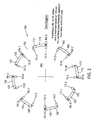
Figure 2 is a schematic illustration of a plurality of segmented waveguides positioned on a stator and a plurality of optical transmitters positioned on the rotor according to the present invention; and -
Figure 3 is a diagram depicting a switcher, encoder and input and output buffers used in the fiber optic rotary joint according to the present invention. - Refer now to
Figure 2 in which a fiber optic rotary joint 100 according to the present invention is depicted. The fiber optic rotary joint includes astator 102 and arotor 104. The fiber optic rotary joint 100 includes eightreceivers RX 0,RX 1 ...RX 7, each on asegmented waveguide assembly reflective surface receiver RX 0,RX 1 ...RX 7, respectively, positioned at one end thereof. Each of thesegmented waveguide assemblies 110 is attached to thestator 102. As depicted inFigure 2 , each of thereceivers Rx 0,RX 1 ...RX 7 is located at the most counterclockwise position for each of the segmented waveguide assemblies 110-180. Each of the segmented waveguides 110-180 is equally circumferentially spaced and there is a gap or area of the existing gantry that is not actively being used for signal transmission. The inactive areas are non-reflective and absorb the transmitted optical signals. For example, there are gaps betweensegmented waveguide assemblies - As depicted in
Figure 2 , there are sixteen transmitters TX A, TX B, TX C . .. TX P which are equally circumferentially spaced on the periphery of therotor 104. - In the position, as depicted in
Figure 2 ,receiver RX 0 will receive an optical signal from transmitter TX A, andreceiver RX 1 will receive an optical signal from transmitter TX C. As therotor 104 to which the transmitters are connected rotates in a clockwise direction as depicted inFigure 2 , for example, an angle 22.5° from the position inFigure 2 , transmitter TX B will be transmitting a signal received byreceiver RX 0 and transmitter TX D will be receiving a signal received byreceiver RX 1. - The present invention can advantageously utilize the inactive areas of the ring (depicted in
Figure 1 ) by using additional sections of waveguide 110-180 with their correspondingpickup fibers RX 0,RX 1 ...RX 7. InFigure 2 , there are eight sectional waveguides 110-180 (22.5° in length, 22.5° spacing), 16source fibers TX 0,TX 1 ... TX P (of equal length, 22.5° spacing), and eightpickup fibers RX 0,RX 1 ... RX 7 (of equal length, positioned at ends of waveguide). At this time, each of the sixteen source fibers TX 0-TX P can transmit the same modulated light source, meaning all eight pickup fibers RX 0 -RX 7 receive the same signal from the same modulated light source. This feature would allow for certain combinations of redundancy in the system and would reduce the amount of optical power required for a particular BER. The received signal could be summed from all of the received signals. - However, the desire is to increase the data rate of the large diameter fiber optic rotary joint 100. The present invention treats each waveguide 112-182 and pickup fiber assembly 110-180 as an individual receiver. Rather than transmitting a single serial data stream through the large fiber optic rotary joint 100 which is limited to the maximum data rate of the sectional waveguide 110-180, the present invention transmits eight individual serial data streams or an eight bit parallel word data stream through the large fiber optic rotary joint 100. By using an encoder or resolver (
Figure 3 ), the position of each source fiber TX 0-TX P relative to the eight waveguides 110-180 can be determined to a very high degree of accuracy. The encoder or resolver signal can be generated be an existing encoder or resolver which is part of the drive mechanism for rotating the rotor in a cat scan machine. If the present invention is used in a device that does not already have an encoder or resolver then one will be provided. The information generated by the encoder orresolver 204 will feed a high speed-switching network 202 ("switcher"). The eight individual channels of data or one eight-bit parallel channel are fed into theswitcher 202. The eight individual channels or one eight-bit parallel channel are described in conjunction with a 40 inch diameter ring. Of course, it should be appreciated that other numbers of channels or bits may be used depending upon various considerations including ring diameter, data rate, etc. Theswitcher 202 is used to route the input data to the appropriate source fiber TX 0-TX P such that continuity is maintained between a specific input channel and a specific waveguide/pickup fiber receiver RX 0-RX 7. Table 1 below shows the degree location, in this example, for turning the transmitter on and off with respect to the input data.TXA TXB TXC TXD TXE TXF TXG TSH THI TXJ TXK TXL BIT O ON 355 332.5 310 287.5 265 242.5 220 197.5 175 152.5 130 107.5 BIT O OFF 22.5 0 337.5 315 292.5 270 247.5 225 202.5 180 157.5 135 BIT 1 ON 40 17.5 355 332.5 310 287.5 265 242.5 220 197.5 175 152.5 BIT 1 OFF 67.5 45 22.5 0 337.5 315 292.5 270 247.5 225 202.5 180 BIT 2 ON 85 62.5 40 17.5 355 332.5 310 287.5 265 242.5 220 197.5 BIT 2 OFF 112.5 90 67.5 45 22.5 0 337.5 315 292.5 270 247.5 225 BIT 3 ON 130 107.5 85 62.5 40 17.5 355 332.5 310 287.5 265 242.5 BIT 3 OFF 157.5 135 112.5 90 67.5 45 22.5 0 337.5 315 292.5 270 BIT 4 ON 175 152.5 130 107.5 85 62.5 40 17.5 355 332.5 310 287.5 BIT 4 OFF 202.5 180 157.5 135 112.5 90 67.5 45 22.5 0 337.5 315 BIT 5 ON 220 197.5 175 152.5 130 107.5 85 62.5 40 17.5 385 332.5 BIT 5 OFF 247.5 225 202.5 180 1575 5 135 112.5 90 67.5 45 22.5 0 BIT 6 ON 265 242.5 220 197.5 175 152.5 130 107.5 85 62.5 40 17.5 BIT 6 OFF 202.5 270 247.5 225 202.5 180 157.5 135 112.5 90 67.5 45 BIT 7 ON 310 287.5 265 242.5 220 197.5 175 152.5 130 107.5 85 62.5 BIT 7 OFF 337.5 315 292.5 270 247.5 225 202.5 180 157.5 135 112.5 90 - This concept is presented in more detail in
Figure 3 . The eight-bit input is connected to the input buffer BUF[0..7]. The contents of the input buffer BUF [0..7] are connected to theswitcher 202 whose control signals are generated by the information from the resolver/encoder 204. In a stationary position, as shown inFigure 2 , theswitcher 202 routes the contents of: - BUF[0] to TX A
- BUF[1] to TX C
- BUF[2] to TX E
- BUF[3] to TX G
- BUF[4] to TX I
- BUF[5] to TX K
- BUF[6] to TX M
- BUF[7] to
TX 0 - BUF[0] to TX B
- BUF[1] to TX D
- BUF[2] to TX F
- BUF[3] to TX H
- BUF [4] to TX J
- BUF [5] to TX L
- BUF [6] to TX N
- BUF [7] to TX P
- It will be readily seen by one of ordinary skill in the art that the present invention fulfills all of the objects set forth above. After reading the foregoing specification, one of ordinary skill will be able to affect various changes, substitutions of equivalents and various other aspects of the invention as broadly disclosed herein. It is therefore intended that the protection granted hereon be limited only by the definition contained in the appended claims and equivalents thereof.
Claims (14)
- A fiber optic rotary joint(100) adapted to be supplied with a plurality of individual data streams, comprising:a stator (102) having a plurality of optical waveguide segments (110, 120, 130, ..., 180) circumferentially spaced thereabout, each of said optical waveguide segments having an optical pickup (RX 0, RX 1, RX 2, ..., RX 7):a rotor (104) mounted for rotation relative to said stator (102), said rotor having a plurality of optical transmitters(TX A, TX B, TX C, ..., TX P) spaced about the periphery of said rotor;a position determining device (204) determining the relative angular position between said transmitters and said optical waveguide segments;a wave division multiplexer for providing multi-bit optical signals to each of the optical transmitters;a switch (202) for routing each Input data stream to the appropriate transmitter that transmits a corresponding optical signal to a predetermined waveguide segment for that determined relative angular position such that each transmitter will transmit an individual optical signal to its associated waveguide at said relative angular position; andwhereby the supplied individual input data streams are transmitted continuously to respective ones of said waveguide segments,wherein said position determining device is one of an encoder and a resolver (204).
- A fiber optic rotary joint as set forth in claim 1 wherein each of said waveguide segments receives an optical signal having a data rate of up to 500 Mbps.
- A fiber optic rotary joint as set forth in claim 1, wherein the maximum data throughput of said rotary joint is 4 Gbps.
- A fiber optic rotary Joint as set forth in claim 1 wherein the maximum data throughput of said rotary joint is 16 Gbps.
- A fiber optic rotary joint as set forth in claim 1 wherein said waveguide segments are spaced equally about said stator inner surface.
- A fiber optic rotary Joint as set forth in claim 1 wherein said transmitters are spaced equally about said rotor.
- A method of transmitting multiple optical signals through a fiber optic rotary joint (100) having a plurality of segmented waveguide segments (110. 120, ... 180) on a stator (102), with each of the segmented waveguide segments having an associated optical receiver (RXO, RX1, ... RX7), and a plurality of optical transmitters (TX A, TX B, ... TX P) on a rotor (104), comprising the steps of:determining the angular position of each optical transmitter relative to each waveguide segment during rotation of the rotor (104);providing multi-bit optical signals to each of the optical transmitters by wave division multiplexing ;routing, based upon the angular position of the optical transmitters,individual data streams to each appropriate transmitter that transmits for that determined angular position corresponding optical signals to a particular waveguide segment; andWherein the step of determining the angular position of each optical transmitter is performed by one of an encoder and a resolver (204).
- The method of claim 7, comprising the further steps of:switching some of the second plurality of optical transmitters on; andswitching the remaining ones of the second plurality of optical transmitters off.
- The method of claim 7, wherein the multiple optical signals is one of a serial data stream and a parallel data stream.
- The method of claim 7, comprising buffering the optical signal before transmission.
- The method of claim 7, wherein alternate ones of the second plurality of optical transmitters are switched on.
- The method of claim 7, and further comprising the additional step of:receiving the multiple optical signals at each of the predetermined optical receivers.
- The method of claim 7, comprising the further step of:reflecting an optical signal off the segmented waveguide into an optical receiver.
- The method of claim 7, comprising the further step of:absorbing reflected optical signals non-reflective segments between segmented waveguides.
Applications Claiming Priority (2)
| Application Number | Priority Date | Filing Date | Title |
|---|---|---|---|
| US629145 | 1984-07-09 | ||
| US09/629,145 US6385367B1 (en) | 2000-07-31 | 2000-07-31 | Parallel data transmission through segmented waveguides of large diameter |
Publications (3)
| Publication Number | Publication Date |
|---|---|
| EP1178338A2 EP1178338A2 (en) | 2002-02-06 |
| EP1178338A3 EP1178338A3 (en) | 2004-04-07 |
| EP1178338B1 true EP1178338B1 (en) | 2008-10-08 |
Family
ID=24521775
Family Applications (1)
| Application Number | Title | Priority Date | Filing Date |
|---|---|---|---|
| EP01118069A Expired - Lifetime EP1178338B1 (en) | 2000-07-31 | 2001-07-25 | Parallel data transmission through segmented waveguides of large diameter |
Country Status (7)
| Country | Link |
|---|---|
| US (1) | US6385367B1 (en) |
| EP (1) | EP1178338B1 (en) |
| JP (2) | JP2002062455A (en) |
| AT (1) | ATE410710T1 (en) |
| CA (1) | CA2352686C (en) |
| DE (1) | DE60136038D1 (en) |
| ES (1) | ES2315251T3 (en) |
Families Citing this family (14)
| Publication number | Priority date | Publication date | Assignee | Title |
|---|---|---|---|---|
| JP3612264B2 (en) * | 2000-07-18 | 2005-01-19 | 株式会社東芝 | Optical transmission device between rotating body and fixed body |
| US6907161B2 (en) * | 2002-11-05 | 2005-06-14 | Moog Components Group Inc. | Fiber optic rotary joint |
| US6980714B2 (en) * | 2003-09-26 | 2005-12-27 | Moog Components Group Inc. | Fiber optic rotary joint and associated reflector assembly |
| US7424634B2 (en) * | 2005-03-14 | 2008-09-09 | Micron Technology, Inc. | System and method for reducing jitter of signals coupled through adjacent signal lines |
| DK2413167T3 (en) | 2006-04-28 | 2014-03-24 | Moog Inc | Methods for mounting the optical rotary joint |
| EP2109235B1 (en) | 2008-04-09 | 2013-05-29 | Siemens Aktiengesellschaft | Rotary joint |
| EP2362948B1 (en) | 2008-12-11 | 2019-02-20 | Moog Inc. | High-power collimating lens assemblies, and methods of reducing the optical power density in collimating lens assemblies |
| JP5385604B2 (en) * | 2008-12-25 | 2014-01-08 | 株式会社トプコン | Optical signal transmission device |
| CA2780481C (en) | 2009-12-03 | 2016-10-25 | Moog Inc. | Fiber optic rotary joints, methods practiced thereby, and fiber optic devices |
| GB2506190B (en) * | 2012-09-25 | 2018-06-27 | Bae Systems Plc | Apparatus and methods for use with optical rotating joint |
| GB2506191B (en) | 2012-09-25 | 2018-06-27 | Bae Systems Plc | Apparatus and methods for use with optical rotating joint |
| CN104467924B (en) * | 2014-12-12 | 2017-05-31 | 北京航星机器制造有限公司 | Method for designing for rotating against data transmission system and system between object |
| US10326561B2 (en) * | 2015-06-24 | 2019-06-18 | Toshiba Medical Systems Corporation | Mirror-ring assembly for bi-directional optical communication between a rotor and a stator |
| US11237336B2 (en) | 2020-04-29 | 2022-02-01 | Northrop Grumman Systems Corporation | Hollow shaft optical rotary joint |
Family Cites Families (22)
| Publication number | Priority date | Publication date | Assignee | Title |
|---|---|---|---|---|
| EP0039475B1 (en) * | 1980-05-05 | 1984-06-13 | International Standard Electric Corporation | Rotary annular signal data coupler |
| EP0115843B1 (en) | 1983-02-04 | 1989-06-28 | Kei Mori | Apparatus for time-sharing light distribution |
| FR2570839B1 (en) | 1984-09-25 | 1986-12-05 | Labo Electronique Physique | COUPLING DEVICE BETWEEN WAVEGUIDES, MONOLITHICALLY INTEGRATED THEREON ONTO A SEMICONDUCTOR SUBSTRATE |
| DE3538035A1 (en) * | 1985-10-25 | 1987-04-30 | Siemens Ag | ROTATING DATA TRANSFER DEVICE |
| US5121419A (en) * | 1986-07-07 | 1992-06-09 | Thomson-Cgr | Computer-aided tomography apparatus |
| US5010254A (en) * | 1989-04-05 | 1991-04-23 | Kabushiki Kaisha Toshiba | System for communicating energy between relatively moving devices |
| IL90853A0 (en) * | 1989-07-03 | 1990-02-09 | Elscint Ltd | Optical communication link |
| FR2670909B1 (en) | 1990-12-21 | 1994-02-11 | Thomson Csf | OPTICAL CONNECTION DEVICE AND DATA PROCESSING APPARATUS PROVIDED WITH OPTICAL TRANSMISSION MEANS. |
| JP3643384B2 (en) * | 1992-01-14 | 2005-04-27 | 株式会社東芝 | X-ray tomography equipment |
| US5239230A (en) | 1992-03-27 | 1993-08-24 | General Electric Company | High brightness discharge light source |
| US5259056A (en) | 1992-03-27 | 1993-11-02 | General Electric Company | Coupler apparatus for use with a high brightness light source |
| US5479545A (en) | 1992-03-27 | 1995-12-26 | General Electric Company | Reverse flared optical coupling member for use with a high brightness light source |
| US5341445A (en) | 1992-03-27 | 1994-08-23 | General Electric Company | Polygonal-shaped optical coupling member for use with a high brightness light source |
| US5420946A (en) * | 1993-03-09 | 1995-05-30 | Tsai; Jian-Hung | Multiple channel optical coupling switch |
| CA2143494C (en) | 1995-02-27 | 2004-09-07 | Takao Tanaka | Light transmitting apparatus |
| US5812713A (en) | 1995-09-20 | 1998-09-22 | General Electric Company | Optical coupling system with bend |
| JPH09308625A (en) * | 1996-05-23 | 1997-12-02 | Toshiba Corp | Optical transmission system |
| DE19728313A1 (en) * | 1997-07-03 | 1999-01-07 | Zf Luftfahrttechnik Gmbh | Angle of rotation sensor |
| DE19728314A1 (en) * | 1997-07-03 | 1999-01-07 | Zf Luftfahrttechnik Gmbh | Signal transmission device |
| US5920667A (en) * | 1997-08-12 | 1999-07-06 | Industrial Technology Research Institute | Switch device for optical fibers |
| US5991478A (en) * | 1997-10-02 | 1999-11-23 | Litton Systems, Incorporated | Fiber optic rotary joint |
| US6104849A (en) * | 1997-10-02 | 2000-08-15 | Litton Systems, Inc. | Fiber optic rotary joint |
-
2000
- 2000-07-31 US US09/629,145 patent/US6385367B1/en not_active Expired - Lifetime
-
2001
- 2001-07-09 CA CA002352686A patent/CA2352686C/en not_active Expired - Fee Related
- 2001-07-25 EP EP01118069A patent/EP1178338B1/en not_active Expired - Lifetime
- 2001-07-25 DE DE60136038T patent/DE60136038D1/en not_active Expired - Lifetime
- 2001-07-25 ES ES01118069T patent/ES2315251T3/en not_active Expired - Lifetime
- 2001-07-25 AT AT01118069T patent/ATE410710T1/en not_active IP Right Cessation
- 2001-07-31 JP JP2001232806A patent/JP2002062455A/en active Pending
-
2013
- 2013-06-26 JP JP2013133369A patent/JP5675901B2/en not_active Expired - Fee Related
Also Published As
| Publication number | Publication date |
|---|---|
| JP2002062455A (en) | 2002-02-28 |
| EP1178338A2 (en) | 2002-02-06 |
| JP2013231989A (en) | 2013-11-14 |
| CA2352686A1 (en) | 2002-01-31 |
| CA2352686C (en) | 2009-09-15 |
| JP5675901B2 (en) | 2015-02-25 |
| EP1178338A3 (en) | 2004-04-07 |
| ES2315251T3 (en) | 2009-04-01 |
| US6385367B1 (en) | 2002-05-07 |
| DE60136038D1 (en) | 2008-11-20 |
| ATE410710T1 (en) | 2008-10-15 |
Similar Documents
| Publication | Publication Date | Title |
|---|---|---|
| JP5675901B2 (en) | Optical fiber rotary joint and optical signal transmission method | |
| EP1019763B1 (en) | Fiber optic rotary joint | |
| CA2540088C (en) | Fiber optic rotary joint and associated reflector assembly | |
| US5991478A (en) | Fiber optic rotary joint | |
| US20080069146A1 (en) | Multi-Channel Data Transmission System for Computer Tomographs | |
| EP1345340B1 (en) | Structure and apparatus for a very short haul, free space interconnect and data link | |
| KR20120093414A (en) | Fiber optic rotary joints, methods practiced thereby, and fiber optic devices | |
| US6937787B2 (en) | Optical high speed rotary joint | |
| US7433556B1 (en) | Optical rotary joint | |
| JP3802589B2 (en) | Bidirectional information transmission and energy simultaneous transmission device | |
| US4898447A (en) | Optoelectronic coupling system | |
| EP1178339B1 (en) | Segmented waveguide for large diameter fiber optic rotary joint | |
| US6856720B2 (en) | Rotating fiber optic switch | |
| US6625339B2 (en) | Optical connection and connection unit for the exchange of data between devices | |
| US5892605A (en) | Optical crossbar using guided spatial division multiplexing | |
| US4973123A (en) | Electro-optical rotary coupling suitable for tape scanners | |
| US6407838B1 (en) | Reconfigurable multi-add/drop module for optical communications | |
| EP1427122B1 (en) | Bidirectional wavelength division multiplexing self-healing ring network | |
| US20030156843A1 (en) | Device for optical signal transmission | |
| US6697184B1 (en) | Method and system for steering a collimated light beam with a pivotable mirror | |
| WO2014049343A1 (en) | Provision of an optical rotating joint installation | |
| US7280760B1 (en) | Upgradeable optical add/drop multiplexer | |
| GB2416258A (en) | Dual optical fibre split data transmission system | |
| EP1294118A4 (en) | DATA TRANSMISSION SYSTEM |
Legal Events
| Date | Code | Title | Description |
|---|---|---|---|
| PUAI | Public reference made under article 153(3) epc to a published international application that has entered the european phase |
Free format text: ORIGINAL CODE: 0009012 |
|
| AK | Designated contracting states |
Kind code of ref document: A2 Designated state(s): AT BE CH CY DE DK ES FI FR GB GR IE IT LI LU MC NL PT SE TR |
|
| AX | Request for extension of the european patent |
Free format text: AL;LT;LV;MK;RO;SI |
|
| RIN1 | Information on inventor provided before grant (corrected) |
Inventor name: PERSAUD, ALEX NALENDRA ARA LIGHT, INC. Inventor name: ROGERS, ROBERT THOMAS |
|
| PUAL | Search report despatched |
Free format text: ORIGINAL CODE: 0009013 |
|
| RIC1 | Information provided on ipc code assigned before grant |
Ipc: 7H 01P 1/06 B Ipc: 7G 02B 6/36 A |
|
| AK | Designated contracting states |
Kind code of ref document: A3 Designated state(s): AT BE CH CY DE DK ES FI FR GB GR IE IT LI LU MC NL PT SE TR |
|
| AX | Request for extension of the european patent |
Extension state: AL LT LV MK RO SI |
|
| RAP1 | Party data changed (applicant data changed or rights of an application transferred) |
Owner name: MOOG COMPONENTS GROUP INC. |
|
| 17P | Request for examination filed |
Effective date: 20040818 |
|
| 17Q | First examination report despatched |
Effective date: 20041105 |
|
| AKX | Designation fees paid |
Designated state(s): AT BE CH CY DE DK ES FI FR GB GR IE IT LI LU MC NL PT SE TR |
|
| GRAP | Despatch of communication of intention to grant a patent |
Free format text: ORIGINAL CODE: EPIDOSNIGR1 |
|
| GRAS | Grant fee paid |
Free format text: ORIGINAL CODE: EPIDOSNIGR3 |
|
| GRAA | (expected) grant |
Free format text: ORIGINAL CODE: 0009210 |
|
| AK | Designated contracting states |
Kind code of ref document: B1 Designated state(s): AT BE CH CY DE DK ES FI FR GB GR IE IT LI LU MC NL PT SE TR |
|
| REG | Reference to a national code |
Ref country code: GB Ref legal event code: FG4D |
|
| REG | Reference to a national code |
Ref country code: CH Ref legal event code: EP |
|
| REG | Reference to a national code |
Ref country code: IE Ref legal event code: FG4D |
|
| REG | Reference to a national code |
Ref country code: CH Ref legal event code: NV Representative=s name: RENTSCH & PARTNER |
|
| REF | Corresponds to: |
Ref document number: 60136038 Country of ref document: DE Date of ref document: 20081120 Kind code of ref document: P |
|
| REG | Reference to a national code |
Ref country code: SE Ref legal event code: TRGR |
|
| REG | Reference to a national code |
Ref country code: ES Ref legal event code: FG2A Ref document number: 2315251 Country of ref document: ES Kind code of ref document: T3 |
|
| PG25 | Lapsed in a contracting state [announced via postgrant information from national office to epo] |
Ref country code: AT Free format text: LAPSE BECAUSE OF FAILURE TO SUBMIT A TRANSLATION OF THE DESCRIPTION OR TO PAY THE FEE WITHIN THE PRESCRIBED TIME-LIMIT Effective date: 20081008 |
|
| PG25 | Lapsed in a contracting state [announced via postgrant information from national office to epo] |
Ref country code: PT Free format text: LAPSE BECAUSE OF FAILURE TO SUBMIT A TRANSLATION OF THE DESCRIPTION OR TO PAY THE FEE WITHIN THE PRESCRIBED TIME-LIMIT Effective date: 20090217 Ref country code: FI Free format text: LAPSE BECAUSE OF FAILURE TO SUBMIT A TRANSLATION OF THE DESCRIPTION OR TO PAY THE FEE WITHIN THE PRESCRIBED TIME-LIMIT Effective date: 20081008 |
|
| PG25 | Lapsed in a contracting state [announced via postgrant information from national office to epo] |
Ref country code: DK Free format text: LAPSE BECAUSE OF FAILURE TO SUBMIT A TRANSLATION OF THE DESCRIPTION OR TO PAY THE FEE WITHIN THE PRESCRIBED TIME-LIMIT Effective date: 20081008 |
|
| PLBE | No opposition filed within time limit |
Free format text: ORIGINAL CODE: 0009261 |
|
| STAA | Information on the status of an ep patent application or granted ep patent |
Free format text: STATUS: NO OPPOSITION FILED WITHIN TIME LIMIT |
|
| 26N | No opposition filed |
Effective date: 20090709 |
|
| PGFP | Annual fee paid to national office [announced via postgrant information from national office to epo] |
Ref country code: ES Payment date: 20090727 Year of fee payment: 9 |
|
| PGFP | Annual fee paid to national office [announced via postgrant information from national office to epo] |
Ref country code: CH Payment date: 20090728 Year of fee payment: 9 Ref country code: SE Payment date: 20090729 Year of fee payment: 9 |
|
| PG25 | Lapsed in a contracting state [announced via postgrant information from national office to epo] |
Ref country code: MC Free format text: LAPSE BECAUSE OF NON-PAYMENT OF DUE FEES Effective date: 20090731 |
|
| PGFP | Annual fee paid to national office [announced via postgrant information from national office to epo] |
Ref country code: IT Payment date: 20090728 Year of fee payment: 9 |
|
| PG25 | Lapsed in a contracting state [announced via postgrant information from national office to epo] |
Ref country code: IE Free format text: LAPSE BECAUSE OF NON-PAYMENT OF DUE FEES Effective date: 20090725 |
|
| PG25 | Lapsed in a contracting state [announced via postgrant information from national office to epo] |
Ref country code: GR Free format text: LAPSE BECAUSE OF FAILURE TO SUBMIT A TRANSLATION OF THE DESCRIPTION OR TO PAY THE FEE WITHIN THE PRESCRIBED TIME-LIMIT Effective date: 20090109 |
|
| PGFP | Annual fee paid to national office [announced via postgrant information from national office to epo] |
Ref country code: FR Payment date: 20100805 Year of fee payment: 10 |
|
| REG | Reference to a national code |
Ref country code: CH Ref legal event code: PL |
|
| PG25 | Lapsed in a contracting state [announced via postgrant information from national office to epo] |
Ref country code: LI Free format text: LAPSE BECAUSE OF NON-PAYMENT OF DUE FEES Effective date: 20100731 Ref country code: CH Free format text: LAPSE BECAUSE OF NON-PAYMENT OF DUE FEES Effective date: 20100731 Ref country code: LU Free format text: LAPSE BECAUSE OF NON-PAYMENT OF DUE FEES Effective date: 20090725 |
|
| PG25 | Lapsed in a contracting state [announced via postgrant information from national office to epo] |
Ref country code: IT Free format text: LAPSE BECAUSE OF NON-PAYMENT OF DUE FEES Effective date: 20100725 |
|
| REG | Reference to a national code |
Ref country code: ES Ref legal event code: FD2A Effective date: 20110818 |
|
| PG25 | Lapsed in a contracting state [announced via postgrant information from national office to epo] |
Ref country code: TR Free format text: LAPSE BECAUSE OF FAILURE TO SUBMIT A TRANSLATION OF THE DESCRIPTION OR TO PAY THE FEE WITHIN THE PRESCRIBED TIME-LIMIT Effective date: 20081008 |
|
| PG25 | Lapsed in a contracting state [announced via postgrant information from national office to epo] |
Ref country code: CY Free format text: LAPSE BECAUSE OF FAILURE TO SUBMIT A TRANSLATION OF THE DESCRIPTION OR TO PAY THE FEE WITHIN THE PRESCRIBED TIME-LIMIT Effective date: 20081008 |
|
| PG25 | Lapsed in a contracting state [announced via postgrant information from national office to epo] |
Ref country code: ES Free format text: LAPSE BECAUSE OF NON-PAYMENT OF DUE FEES Effective date: 20100726 |
|
| REG | Reference to a national code |
Ref country code: FR Ref legal event code: ST Effective date: 20120330 |
|
| PG25 | Lapsed in a contracting state [announced via postgrant information from national office to epo] |
Ref country code: FR Free format text: LAPSE BECAUSE OF NON-PAYMENT OF DUE FEES Effective date: 20110801 |
|
| PG25 | Lapsed in a contracting state [announced via postgrant information from national office to epo] |
Ref country code: SE Free format text: LAPSE BECAUSE OF NON-PAYMENT OF DUE FEES Effective date: 20100726 |
|
| PGFP | Annual fee paid to national office [announced via postgrant information from national office to epo] |
Ref country code: NL Payment date: 20180826 Year of fee payment: 18 Ref country code: DE Payment date: 20180829 Year of fee payment: 18 |
|
| PGFP | Annual fee paid to national office [announced via postgrant information from national office to epo] |
Ref country code: GB Payment date: 20180828 Year of fee payment: 18 Ref country code: BE Payment date: 20180827 Year of fee payment: 18 |
|
| REG | Reference to a national code |
Ref country code: DE Ref legal event code: R119 Ref document number: 60136038 Country of ref document: DE |
|
| GBPC | Gb: european patent ceased through non-payment of renewal fee |
Effective date: 20190725 |
|
| REG | Reference to a national code |
Ref country code: BE Ref legal event code: MM Effective date: 20190731 |
|
| PG25 | Lapsed in a contracting state [announced via postgrant information from national office to epo] |
Ref country code: DE Free format text: LAPSE BECAUSE OF NON-PAYMENT OF DUE FEES Effective date: 20200201 Ref country code: GB Free format text: LAPSE BECAUSE OF NON-PAYMENT OF DUE FEES Effective date: 20190725 Ref country code: NL Free format text: LAPSE BECAUSE OF NON-PAYMENT OF DUE FEES Effective date: 20190801 |
|
| REG | Reference to a national code |
Ref country code: NL Ref legal event code: MM Effective date: 20190801 |
|
| PG25 | Lapsed in a contracting state [announced via postgrant information from national office to epo] |
Ref country code: BE Free format text: LAPSE BECAUSE OF NON-PAYMENT OF DUE FEES Effective date: 20190731 |