EP1178192A2 - Apparatus for controlling supercharging pressure in internal combustion engine - Google Patents
Apparatus for controlling supercharging pressure in internal combustion engine Download PDFInfo
- Publication number
- EP1178192A2 EP1178192A2 EP01118251A EP01118251A EP1178192A2 EP 1178192 A2 EP1178192 A2 EP 1178192A2 EP 01118251 A EP01118251 A EP 01118251A EP 01118251 A EP01118251 A EP 01118251A EP 1178192 A2 EP1178192 A2 EP 1178192A2
- Authority
- EP
- European Patent Office
- Prior art keywords
- supercharging pressure
- engine
- variable
- opening
- vanes
- Prior art date
- Legal status (The legal status is an assumption and is not a legal conclusion. Google has not performed a legal analysis and makes no representation as to the accuracy of the status listed.)
- Granted
Links
- 238000002485 combustion reaction Methods 0.000 title claims abstract description 29
- XLYOFNOQVPJJNP-UHFFFAOYSA-N water Substances O XLYOFNOQVPJJNP-UHFFFAOYSA-N 0.000 claims abstract description 15
- 230000008859 change Effects 0.000 claims abstract description 6
- 230000003134 recirculating effect Effects 0.000 claims description 20
- 239000000295 fuel oil Substances 0.000 abstract description 12
- 238000006073 displacement reaction Methods 0.000 abstract description 8
- 239000007789 gas Substances 0.000 description 28
- 230000001276 controlling effect Effects 0.000 description 17
- 230000014509 gene expression Effects 0.000 description 10
- 238000000034 method Methods 0.000 description 7
- 238000011144 upstream manufacturing Methods 0.000 description 5
- 230000008569 process Effects 0.000 description 4
- 239000000446 fuel Substances 0.000 description 3
- 238000002347 injection Methods 0.000 description 3
- 239000007924 injection Substances 0.000 description 3
- MWUXSHHQAYIFBG-UHFFFAOYSA-N nitrogen oxide Inorganic materials O=[N] MWUXSHHQAYIFBG-UHFFFAOYSA-N 0.000 description 3
- 239000000779 smoke Substances 0.000 description 3
- 230000009467 reduction Effects 0.000 description 2
- 230000001105 regulatory effect Effects 0.000 description 2
- 230000004044 response Effects 0.000 description 2
- 230000001133 acceleration Effects 0.000 description 1
- 230000015572 biosynthetic process Effects 0.000 description 1
- 230000007613 environmental effect Effects 0.000 description 1
- 238000012423 maintenance Methods 0.000 description 1
- 238000009987 spinning Methods 0.000 description 1
Images


Classifications
-
- F—MECHANICAL ENGINEERING; LIGHTING; HEATING; WEAPONS; BLASTING
- F02—COMBUSTION ENGINES; HOT-GAS OR COMBUSTION-PRODUCT ENGINE PLANTS
- F02D—CONTROLLING COMBUSTION ENGINES
- F02D41/00—Electrical control of supply of combustible mixture or its constituents
- F02D41/0025—Controlling engines characterised by use of non-liquid fuels, pluralities of fuels, or non-fuel substances added to the combustible mixtures
- F02D41/0047—Controlling exhaust gas recirculation [EGR]
- F02D41/0065—Specific aspects of external EGR control
-
- F—MECHANICAL ENGINEERING; LIGHTING; HEATING; WEAPONS; BLASTING
- F02—COMBUSTION ENGINES; HOT-GAS OR COMBUSTION-PRODUCT ENGINE PLANTS
- F02B—INTERNAL-COMBUSTION PISTON ENGINES; COMBUSTION ENGINES IN GENERAL
- F02B37/00—Engines characterised by provision of pumps driven at least for part of the time by exhaust
- F02B37/12—Control of the pumps
- F02B37/24—Control of the pumps by using pumps or turbines with adjustable guide vanes
-
- F—MECHANICAL ENGINEERING; LIGHTING; HEATING; WEAPONS; BLASTING
- F02—COMBUSTION ENGINES; HOT-GAS OR COMBUSTION-PRODUCT ENGINE PLANTS
- F02D—CONTROLLING COMBUSTION ENGINES
- F02D23/00—Controlling engines characterised by their being supercharged
- F02D23/02—Controlling engines characterised by their being supercharged the engines being of fuel-injection type
-
- F—MECHANICAL ENGINEERING; LIGHTING; HEATING; WEAPONS; BLASTING
- F02—COMBUSTION ENGINES; HOT-GAS OR COMBUSTION-PRODUCT ENGINE PLANTS
- F02B—INTERNAL-COMBUSTION PISTON ENGINES; COMBUSTION ENGINES IN GENERAL
- F02B3/00—Engines characterised by air compression and subsequent fuel addition
- F02B3/06—Engines characterised by air compression and subsequent fuel addition with compression ignition
-
- F—MECHANICAL ENGINEERING; LIGHTING; HEATING; WEAPONS; BLASTING
- F02—COMBUSTION ENGINES; HOT-GAS OR COMBUSTION-PRODUCT ENGINE PLANTS
- F02D—CONTROLLING COMBUSTION ENGINES
- F02D2200/00—Input parameters for engine control
- F02D2200/02—Input parameters for engine control the parameters being related to the engine
- F02D2200/04—Engine intake system parameters
- F02D2200/0414—Air temperature
-
- F—MECHANICAL ENGINEERING; LIGHTING; HEATING; WEAPONS; BLASTING
- F02—COMBUSTION ENGINES; HOT-GAS OR COMBUSTION-PRODUCT ENGINE PLANTS
- F02D—CONTROLLING COMBUSTION ENGINES
- F02D2200/00—Input parameters for engine control
- F02D2200/70—Input parameters for engine control said parameters being related to the vehicle exterior
- F02D2200/703—Atmospheric pressure
-
- F—MECHANICAL ENGINEERING; LIGHTING; HEATING; WEAPONS; BLASTING
- F02—COMBUSTION ENGINES; HOT-GAS OR COMBUSTION-PRODUCT ENGINE PLANTS
- F02M—SUPPLYING COMBUSTION ENGINES IN GENERAL WITH COMBUSTIBLE MIXTURES OR CONSTITUENTS THEREOF
- F02M26/00—Engine-pertinent apparatus for adding exhaust gases to combustion-air, main fuel or fuel-air mixture, e.g. by exhaust gas recirculation [EGR] systems
- F02M26/02—EGR systems specially adapted for supercharged engines
- F02M26/04—EGR systems specially adapted for supercharged engines with a single turbocharger
- F02M26/05—High pressure loops, i.e. wherein recirculated exhaust gas is taken out from the exhaust system upstream of the turbine and reintroduced into the intake system downstream of the compressor
-
- F—MECHANICAL ENGINEERING; LIGHTING; HEATING; WEAPONS; BLASTING
- F02—COMBUSTION ENGINES; HOT-GAS OR COMBUSTION-PRODUCT ENGINE PLANTS
- F02M—SUPPLYING COMBUSTION ENGINES IN GENERAL WITH COMBUSTIBLE MIXTURES OR CONSTITUENTS THEREOF
- F02M26/00—Engine-pertinent apparatus for adding exhaust gases to combustion-air, main fuel or fuel-air mixture, e.g. by exhaust gas recirculation [EGR] systems
- F02M26/02—EGR systems specially adapted for supercharged engines
- F02M26/09—Constructional details, e.g. structural combinations of EGR systems and supercharger systems; Arrangement of the EGR and supercharger systems with respect to the engine
- F02M26/10—Constructional details, e.g. structural combinations of EGR systems and supercharger systems; Arrangement of the EGR and supercharger systems with respect to the engine having means to increase the pressure difference between the exhaust and intake system, e.g. venturis, variable geometry turbines, check valves using pressure pulsations or throttles in the air intake or exhaust system
-
- Y—GENERAL TAGGING OF NEW TECHNOLOGICAL DEVELOPMENTS; GENERAL TAGGING OF CROSS-SECTIONAL TECHNOLOGIES SPANNING OVER SEVERAL SECTIONS OF THE IPC; TECHNICAL SUBJECTS COVERED BY FORMER USPC CROSS-REFERENCE ART COLLECTIONS [XRACs] AND DIGESTS
- Y02—TECHNOLOGIES OR APPLICATIONS FOR MITIGATION OR ADAPTATION AGAINST CLIMATE CHANGE
- Y02T—CLIMATE CHANGE MITIGATION TECHNOLOGIES RELATED TO TRANSPORTATION
- Y02T10/00—Road transport of goods or passengers
- Y02T10/10—Internal combustion engine [ICE] based vehicles
- Y02T10/12—Improving ICE efficiencies
-
- Y—GENERAL TAGGING OF NEW TECHNOLOGICAL DEVELOPMENTS; GENERAL TAGGING OF CROSS-SECTIONAL TECHNOLOGIES SPANNING OVER SEVERAL SECTIONS OF THE IPC; TECHNICAL SUBJECTS COVERED BY FORMER USPC CROSS-REFERENCE ART COLLECTIONS [XRACs] AND DIGESTS
- Y02—TECHNOLOGIES OR APPLICATIONS FOR MITIGATION OR ADAPTATION AGAINST CLIMATE CHANGE
- Y02T—CLIMATE CHANGE MITIGATION TECHNOLOGIES RELATED TO TRANSPORTATION
- Y02T10/00—Road transport of goods or passengers
- Y02T10/10—Internal combustion engine [ICE] based vehicles
- Y02T10/40—Engine management systems
Definitions
- the present invention relates to an apparatus for controlling supercharging pressure in an internal combustion engine, and more specifically, to an apparatus for controlling supercharging pressure in an intake passage of an internal combustion engine having a variable displacement turbo-charger.
- Japanese Unexamined Patent Publication No. Hei 8-270454 discloses a vehicular internal combustion engine.
- This engine is provided with a variable displacement turbo-charger, which includes a turbine and a built-in variable position vanes, and an exhaust gas recirculator, which includes a recirculating passage and an exhaust gas recirculating valve (EGR valve) located in the recirculating passage.
- the exhaust gas recirculator connects the exhaust passage and the intake passage to each other.
- the variable displacement turbo-charger changes the pressure of the gas in the exhaust passage by changing the opening of the variable vanes. A small opening of the variable vanes increases the pressure of the gas in the exhaust passage; and a large opening of the variable vanes reduces the pressure of the gas in the exhaust passage.
- the exhaust gas recirculator feeds some of the gas in the exhaust passage back to the intake passage, through the EGR valve, based on the difference between the upstream pressure and the downstream pressure of the EGR valve to reduce the combustion temperature in the combustion chamber connected to the intake passage. This inhibits formation of nitrogen oxides (Nox).
- the optimum amount of exhaust gas to be recirculated in accordance with the load of the internal combustion engine is decided by controlling the variable vanes or the EGR valve.
- the supercharging pressure in the intake passage is held at a desired level under feedback control of the variable vanes.
- the opening of the variable vanes is controlled to steer the actual supercharging pressure to the target supercharging pressure.
- variable vanes are used to determine both the quantity of exhaust gas to be recirculated and the supercharging pressure.
- Such an internal combustion engine is extremely useful in that it can recirculate an optimum quantity of exhaust gas under control of the opening of the variable vanes.
- this engine has problems in the process of approximating the actual supercharging pressure to the target supercharging pressure under control of the opening of the variable vanes.
- the upstream pressure of the EGR valve in the above internal combustion engine starts to increase earlier than the downstream pressure thereof. This increases the difference between the upstream pressure and the downstream pressure of the EGR valve. With the increase in the differential pressure, an excessive amount of exhaust gas passes through the recirculating passage, which releases black smoke from the exhaust gas system.
- the opening of the variable vanes is suitably controlled depending on the operational status of the internal combustion engine.
- an apparatus for controlling supercharging pressure in an internal combustion engine includes an exhaust passage, a turbine located in the exhaust passage, an intake passage, a compressor located in the intake passage, a recirculating passage and a control valve located in the recirculating passage.
- the turbine has variable position vanes which open and close to change the flow rate of an exhaust gas through the turbine.
- the exhaust gas applies a driving torque to the turbine.
- the compressor supplies air to the internal combustion engine depending on the driving torque of the turbine.
- the recirculating passage connects the exhaust passage and the intake passage to each other Lo recirculate exhaust gas from the exhaust passage to the intake passage.
- the position of the control valve is varied to adjust the quantity of exhaust gas passing through the recirculating passage.
- the apparatus is characterized in that the position of the variable vanes is controlled according to the position of the control valve.
- Fig. 1 is a schematic view showing pertinent portions of an automotive diesel engine in the present invention.
- a diesel engine 10 which is employed here as the internal combustion engine, has a combustion chamber 12.
- the combustion chamber 12 is connected to an exhaust passage 20 and to an intake passage 22 through a discharge port and a suction port, respectively.
- a fuel injection nozzle 14 is located in the combustion chamber 12.
- a quantity of fuel which depends on the degree of depression of the accelerator pedal, is injected from the fuel injection nozzle 14 toward the combustion chamber 12.
- the diesel engine 10 also has a variable displacement turbo-charger 30 for controlling supercharging pressure.
- the turbo-charger 30 has a turbine 32 attached to the exhaust passage 20 and a compressor 34 attached to the intake passage 22. Torque generated by the turbine 32 drives the compressor 34 to feed compressed air to the intake passage 22. Thus, when exhaust gas is exhausted from the combustion chamber 12 to the exhaust passage 20, a torque, which depends on the pressure of the exhaust gas, is applied to the compressor 34. The compressor 34 is then driven to force compressed air having a predetermined pressure (supercharging pressure) to the intake system of the diesel engine 10.
- the turbine 32 has variable position vanes 36.
- the variable vanes 36 are opened or closed to change the flow rate of the exhaust gas passing through the turbine 32.
- the variable vanes 36 are arranged around the periphery of a rotor (not shown) and are driven by an actuator 40.
- the actuator 40 is connected to a vacuum pump (not shown) serving as a negative pressure source through a vacuum regulating valve (VRV) 42.
- the VRV 42 adjusts the negative pressure generated by the vacuum pump to drive the variable vanes 36 so that they are opened or closed.
- the VN opening the opening, or position, of the variable vanes 36
- a recirculating passage 24 is located between the upstream side of the turbine 32 in the exhaust passage 20 and the downstream side of the compressor 34 in the intake passage 22.
- the recirculating passage 24 communicates with the exhaust passage 20 and the intake passage 22.
- the recirculating passage 24 includes an exhaust gas recirculating valve (EGR valve) 50 for regulating the recirculating passage.
- An actuator (not shown) opens or closes the EGR valve 50.
- the diesel engine 10 in this embodiment is provided with various detectors for detecting the load of the diesel engine and the operational status thereof. More specifically, the diesel engine 10 has a revolution speed sensor 60, a water temperature sensor 62, a supercharging pressure/atmospheric pressure sensor 64 and an atmospheric temperature sensor 68.
- the revolution speed sensor 60 detects the revolution speed N of the engine.
- the water temperature sensor 62 detects the water temperature Tw in the engine.
- the supercharging pressure/atmospheric pressure sensor 64 is located in the intake passage 22 on the downstream side of the compressor 34, through a vacuum switching valve (VSV) 44.
- the supercharging pressure/atmospheric pressure sensor 64 detects either the supercharging pressurc Pb in Lhe engine or the atmospheric pressure Pa by operating the VSV 44.
- the atmospheric temperature sensor 68 which detects the atmospheric temperature Ta, is located in the intake passage 22 on the upstream side of the compressor 34.
- the revolution speed sensor 60, the water temperature sensor 62, the supercharging pressure/atmospheric pressure sensor 64 and the atmospheric temperature sensor 68 are all connected to an electronic control unit (ECU) 70.
- the respective data detected by the sensors are input to the ECU 70.
- control signals based on the input data are output to the variable vanes 36 and to the EGR valve 50.
- Step S10 the engine revolution speed N, the fuel oil consumption rate Q, the engine water temperature Tw, the supercharging pressure Pb, the atmospheric pressure Pa, the atmospheric temperature Ta and the EGR valve opening coefficient Ec are detected.
- the sensors 60, 62, 64 and 68 detect the engine revolution speed N, the engine water temperature Tw, the supercharging pressure Pb, the atmospheric pressure Pa and the atmospheric temperature Ta, respectively, and send the detected data to the ECU 70.
- the ECU 70 reads the fuel oil consumption Q as data for controlling the injection nozzle, and reads the EGR valve opening coefficient Ec as data for controlling the actuator 40 for driving the EGR valve.
- the EGR valve opening coefficient Ec is set depending on the opening position of the EGR valve 50, for example, from 0 to 1 (0 represents a totally closed state and 1 means a fully opened state).
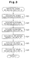
- Step S20 a target VN opening position Vt of the variable vanes 36 is calculated based on the detected data.
- the actuator 40 is controlled based on the target VN opening position Vt, which is calculated to adjust the actual VN opening of the variable vanes 36 to a desired position.
- the opening position of the variable vanes 36 is controlled depending not only on the operational status of the engine, including the engine revolution speed N, the fuel oil consumption Q, engine water temperature Tw, the supercharging pressure Pb, the atmospheric pressure Pa and the atmospheric temperature Ta but also on the position, or opening size, of the EGR valve 50.
- the target VN opening position Vt of the variable vanes 36 shown in Fig. 3 is calculated according to Expressions (1) to (13) shown in Fig. 4.
- map functions based on predetermined maps are represented by f1 to f7, h1, h2 and g1 to g3, respectively.
- a target supercharging pressure Pt is calculated.
- the target supercharging pressure Pt is selected from the smallest of the basic target supercharging pressure Pb1 and the maximum target supercharging pressure Pb3.
- the basic target supercharging pressure Pb1 is set according to a map, which is a function of the engine revolution speed N and the fuel oil consumption Q (see Expression (1) in Fig. 4).
- the maximum target supercharging pressure Pb3 is set by correcting the basic maximum target supercharging pressure Pb2 in the basic target supercharging pressure Pb1 (see Expression (2) in Fig. 4) based on the atmospheric pressure Pa, the engine water temperature Tw and atmospheric temperature Ta (see Expression (3) in Fig. 4).
- the basic target supercharging pressure Pb1 is indicated by the thin solid line (which partly overlaps the thick solid line).
- the basic target supercharging pressure Pb1 is set depending on the correlation between the engine load (engine revolution speed N and fuel oil consumption Q) and the target supercharging pressure. In the range where the engine load is greater than 100%, the basic target supercharging pressure Pb1 is the basic maximum target supercharging pressure Pb2.
- the basic maximum target supercharging pressure Pb2 is the maximum limit of the basic target supercharging pressure Pb1. The limit includes the limit of the revolution speed of the turbine 32 and the limit of the pressure in the cylinders of the engine.
- the basic maximum target supercharging pressure Pb2 is corrected based on the atmospheric pressure Pa, the engine water temperature Tw and the atmospheric temperature Ta to find Pb3.
- the target supercharging pressure Pt is set.
- the target supercharging pressure is set by shifting the basic target supercharging pressure Pb1 (dashed line in Fig. 5) horizontally rightward such that the target supercharging pressure under 100% load coincides with the maximum target supercharging pressure.
- This allows the target supercharging pressure to maintain the maximum limit under 100% load.
- the target supercharging pressure under a low load region of less than 100% becomes lower than the uncorrected preset value.
- Correction is carried out in this embodiment to select the smaller of the basic target supercharging pressure Pb1 and the maximum target supercharging pressure Pb3 as the target supercharging pressure, as indicated by the thick solid line in Fig. 5. This maintains the maintenance of the maximum limit at the maximum target supercharging pressure Pb3 under 100% load and prevents the preset target supercharging pressure from dropping in the low load region.
- this embodiment not only prevents a reduction in the target supercharging pressure in the low load region caused by disturbances including, for example, changes in the atmospheric pressure Pa, changes in the engine water temperature Tw and changes in the atmospheric temperature Ta, but also prevents the turbine 32 from spinning too rapidly and prevents the internal pressure of the cylinders in the engine 10 from becoming too high, which protects the turbo-charger 30 and the diesel engine 10 from damage.
- Step S22 in Fig. 3 the minimum VN opening position Vi of the variable vanes 36 in the opening direction is calculated.
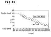
- the minimum VN opening Vi is set according to a map, which is a function of the engine revolution speed N according to Expression (5) in Fig. 4 (see Fig. 10).
- the correlation between the engine revolution speed N (rpm) and the minimum VN opening position Vi (%) gives a limit value in the opening direction of the variable vanes 36, as indicated by the limit value line in Fig. 10.
- the part above the solid line in Fig. 10 is defined as an applicable region.
- the minimum VN opening position Vi when the minimum VN opening position Vi is 0 (%), the variable vanes 36 are opened fully, and when Vi is 100 (%), the variable vanes 36 are totally closed.
- the limit value in the minimum VN opening position Vi in the opening direction the actual supercharging pressure exceeds the target supercharging pressure when the acceleration pedal is because of the residual supercharging pressure, so that the VN opening is controlled in the opening direction. Further, starting up of supercharging again when the engine 10 is reaccelerated is promoted to ensure reacceleration performance.
- Step S23 in Fig. 3 the maximum VN opening Va in the closing direction is calculated.
- the maximum VN opening Va is set according to Expressions (6) to (10) in Fig. 4.
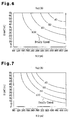
- the maximum VN opening Val when the EGR valve 50 is totally closed and the maximum VN opening Va2 when the EGR valve 50 is opened fully are determined.
- both the maximum VN opening Val and the maximum VN opening Va2 are set according to maps determined respectively as functions of the engine revolution speed N and fuel oil consumption Q (see Figs. 6 and 7). As shown in Figs.6 and 7, the maximum VN opening values Val (%) and Va2 (%) are set depending on the engine revolution speed N (rpm) and the fuel oil consumption Q (mm 3 /stroke). In Figs. 6 and 7, the lines (100 %) represent the state where the variable vanes 36 are totally closed.
- the maximum VN opening Va when the EGR valve 50 has a predetermined degree of opening is calculated based on the EGR valve coefficient Ec (see Equation (10) in Fig. 4).
- the supercharging pressure correction factor Pf in Equation (10) is set up according to a map determined based on the engine revolution speed N and the supercharging pressure difference Pd (see Equation (9) in Fig. 4).
- the supercharging pressure difference Pd is the difference between the target supercharging pressure Pt and the actual supercharging pressure Pb (Equation (8) in Fig. 4).
- the VN opening position is controlled in the closing direction in the transitional phase where the variable vanes 36 are controlled to direct the actual supercharging pressure to the target supercharging pressure. This prevents an excessive amount of exhaust gas from flowing into the recirculating passage 24 and limits the amount of black smoke released from the exhaust system. Further, the limit value set in the direction of closing the variable vanes 36 controls limits of the supercharging pressure and prevents overspeeding of the turbine 32, for example, when the EGR valve 50 is totally closed.
- a VN opening feedback variable Vc is calculated to serve as a feedback control variable.
- the VN opening feedback variable Vc can be obtained by adding the integral (first term), the proportional (second term) and the differential (third term) as shown by Expression (11) in Fig. 4. These terms can be set according to maps determined respectively based on the engine revolution speed N, fuel oil consumption Q, the target supercharging pressure Pt and actual supercharging pressure Pb.
- the gain of the proportional (second term) and that of the differential (third term) are changed depending on the coefficient g2 (N,Q) and the coefficient g3 (N,Q) respectively.
- VN opening feedback variable Vc is corrected to an optimum value depending on the operational status of the diesel engine 10 (e.g., engine load, turbine revolution speed and supercharging pressure). This correction prevents, for example, overspeeding of the turbine 32.
- the variable gains of the proportional and differential enable more suitable control of supercharging pressure than fixed gains.
- a basic VN opening Vb is calculated (see Equation (12) in Fig. 4).
- the basic VN opening Vb is set up according to a map determined based on the engine revolution speed N (rpm) and the fuel oil consumption Q (mm 3 /stroke) (see Fig. 8).
- the 100% line represents the state where the variable vanes are closed totally.
- the target VN opening Vt is calculated.
- the target VN opening Vt is set based on the minimum VN opening Vi, maximum VN opening Va, VN opening feedback variable Vc and basic VN opening Vb calculated in steps S22 to S25 (see Equation (13) in Fig. 4). More specifically, the minimum VN opening Vi is compared with the sum of the basic VN opening Vb and the VN opening feedback variable Vc, and the greater of the two is selected. Further, the selected opening is compared with the maximum VN opening Va, and the smaller of the two is selected as the target VN opening Vt.
- variable vanes 36 are controlled depending on the opening of the EGR valve 50 to adjust the supercharging air pressure. This enables fine control of the supercharging pressure in diesel engines 10 having the function of controlling supercharging pressure and the function of controlling the quantity of exhaust gas to be recirculated.
- the operational range of the variable vanes 36 is limited depending on the opening of the EGR valve 50.
- the VN opening is controlled in the closing direction. This prevents an excessive amount of exhaust gas from flowing through the recirculating passage 24 and minimizes the amount of black smoke released from the exhaust system.
- Setting the limit value in the closing direction of the variable vanes 36 inhibits excessive increase in the supercharging pressure to prevent overspeeding of the turbine 32, for example, when the EGR valve 50 is totally closed.
- the limit value set in the direction of opening the variable vanes 36 promotes the starting up of supercharging upon reacceleration of the engine to improve reacceleration response.
- this embodiment prevents a reduction in the target supercharging pressure Pt caused by disturbances including, for example, changes in atmospheric pressure Pa, changes in engine water temperature Tw and changes in atmospheric temperature Ta, from occurring in the low engine load region. Not only are overspeeding of the turbine 32 and excessive increases in the cylinder pressures in the engine 10 prevented, but the turbo-charger 30 and the diesel engine 10 are protected from damage.
- VN opening feedback variable Vc is corrected to an optimum value depending on the operational status of the diesel engine 10 (including engine load, turbine revolution speed and supercharging pressure), so that overspeeding is prevented from occurring in the turbine 32.
- internal combustion engine includes various kinds of engines including diesel engines and gasoline engines. Therefore, while an apparatus for controlling supercharging pressure in a diesel engine 10 were described in the above embodiment, the present invention can be applied to other types of internal combustion engines.
- the present invention can be applied, for example, to gasoline engines, particularly to a lean-burn engine that exhausts relatively large amounts of unburned components.
- the diesel engine (10) is provided with a variable displacement turbo-charger (30) for adjusting the supercharging air pressure in an intake passage (22).
- the turbo-charger (30) includes a turbine (32) having variable vanes (36).
- the variable vanes (36) open and close to change the flow rate of exhaust gas passing through the turbine (32).
- the variable vanes (36) are controlled based on the operational status of the engine (10), including the engine speed N, the fuel oil consumption Q, the engine water temperature Tw, the supercharging pressure Pb, the atmospheric pressure Pa and the atmospheric temperature Ta, and the position of an EGR valve (50).
- the variable vanes (36) are suitably controlled according to the operational status of the internal combustion engine to achieve fine control of the supercharging pressure.
Landscapes
- Engineering & Computer Science (AREA)
- Chemical & Material Sciences (AREA)
- Combustion & Propulsion (AREA)
- Mechanical Engineering (AREA)
- General Engineering & Computer Science (AREA)
- Supercharger (AREA)
- Exhaust-Gas Circulating Devices (AREA)
Abstract
Description
Claims (6)
- An apparatus for controlling supercharging pressure in an internal combustion engine, wherein the engine includes:the apparatus being characterized in that the position of the variable vanes (36) is controlled according to the position of the control valve (50).an exhaust passage (20);a turbine (32) located in the exhaust passage (20), the turbine (32) having variable position vanes (36), which open and close to change the flow rate of an exhaust gas through the turbine, wherein the exhaust gas applies a driving torque to the turbine (32);an intake passage (22);a compressor (34) located in the intake passage (22), the compressor (34) supplying air to the internal combustion engine depending on the driving torque of the turbine (32);a recirculating passage (24) connecting the exhaust passage (20) and the intake passage (22) to each other to recirculate exhaust gas from the exhaust passage (20) to the intake passage (22); anda control valve (50) located in the recirculating passage (24), wherein position of the valve (50) is varied to adjust the quantity of exhaust gas passing through the recirculating passage (24);
- The apparatus according to Claim 1 characterized in that a limit value (Va) is set to limit the position of the variable vanes (36) when the vanes (36) are being closed.
- The apparatus according to Claim 1 or 2 characterized in that a limit value (Vi) is set to limit the position of the variable vanes (36) when the vanes (36) are being opened.
- The apparatus according to Claim 1 characterized in that the variable vanes (36) are controlled such that the actual supercharging pressure (Pb) is directed to a smaller supercharging pressure (Pt) that is selected from a basic target supercharging pressure (Pb1) and a maximum target supercharging pressure (Pb3), which are determined based on the operational status of the internal combustion engine.
- The apparatus according to Claim 4 characterized in that the maximum target supercharging pressure (Pb3) is set by correcting a maximum value of the basic target supercharging pressure (Pb1) based on the atmospheric pressure (Pa), an engine water temperature (Tw) and the atmospheric temperature (Ta).
- The apparatus according to Claim 1 characterized in that the position of the variable vanes (36) is feedback-controlled, and a gain defining a feedback variable (Vc) changes depending on the supercharging pressure (Pb,Pt).
Applications Claiming Priority (2)
| Application Number | Priority Date | Filing Date | Title |
|---|---|---|---|
| JP2000232022A JP3733281B2 (en) | 2000-07-31 | 2000-07-31 | Supercharging pressure control device and supercharging pressure control method for internal combustion engine |
| JP2000232022 | 2000-07-31 |
Publications (3)
| Publication Number | Publication Date |
|---|---|
| EP1178192A2 true EP1178192A2 (en) | 2002-02-06 |
| EP1178192A3 EP1178192A3 (en) | 2004-09-08 |
| EP1178192B1 EP1178192B1 (en) | 2012-12-19 |
Family
ID=18724765
Family Applications (1)
| Application Number | Title | Priority Date | Filing Date |
|---|---|---|---|
| EP01118251A Expired - Lifetime EP1178192B1 (en) | 2000-07-31 | 2001-07-30 | Apparatus for controlling supercharging pressure in internal combustion engine |
Country Status (2)
| Country | Link |
|---|---|
| EP (1) | EP1178192B1 (en) |
| JP (1) | JP3733281B2 (en) |
Cited By (24)
| Publication number | Priority date | Publication date | Assignee | Title |
|---|---|---|---|---|
| WO2004074660A1 (en) * | 2003-02-20 | 2004-09-02 | Caterpillar Inc. | Compressed engine working on a late clising miller cycle |
| EP1471234A3 (en) * | 2003-04-23 | 2006-07-19 | Robert Bosch Gmbh | Method and device for operating an internal combustion engine |
| EP1375876A3 (en) * | 2002-06-28 | 2007-01-10 | Kabushiki Kaisha Toyota Jidoshokki | Apparatus and method for controlling EGR in an engine |
| US7178492B2 (en) | 2002-05-14 | 2007-02-20 | Caterpillar Inc | Air and fuel supply system for combustion engine |
| WO2007000551A3 (en) * | 2005-06-01 | 2007-02-22 | Renault Sa | Internal combustion engine control method |
| FR2890695A1 (en) * | 2005-09-09 | 2007-03-16 | Renault Sas | METHOD FOR CONTROLLING AN INTERNAL COMBUSTION ENGINE |
| US7191743B2 (en) | 2002-05-14 | 2007-03-20 | Caterpillar Inc | Air and fuel supply system for a combustion engine |
| US7201121B2 (en) | 2002-02-04 | 2007-04-10 | Caterpillar Inc | Combustion engine including fluidically-driven engine valve actuator |
| US7204213B2 (en) | 2002-05-14 | 2007-04-17 | Caterpillar Inc | Air and fuel supply system for combustion engine |
| US7222614B2 (en) | 1996-07-17 | 2007-05-29 | Bryant Clyde C | Internal combustion engine and working cycle |
| US7252054B2 (en) | 2002-05-14 | 2007-08-07 | Caterpillar Inc | Combustion engine including cam phase-shifting |
| US7281527B1 (en) | 1996-07-17 | 2007-10-16 | Bryant Clyde C | Internal combustion engine and working cycle |
| FR2911918A1 (en) * | 2007-01-29 | 2008-08-01 | Renault Sas | Variable geometry type turbocharger controlling system for oil engine of motor vehicle, has control unit including control loops controlling displacement and angular position of blades based on operation point of engine, respectively |
| US7571608B2 (en) * | 2005-11-28 | 2009-08-11 | General Electric Company | Turbocharged engine system and method of operation |
| WO2010115421A1 (en) * | 2009-04-08 | 2010-10-14 | Man Diesel & Turbo Se | Turbocharger system, drive system equipped therewith and method for operating said drive system |
| US8215292B2 (en) | 1996-07-17 | 2012-07-10 | Bryant Clyde C | Internal combustion engine and working cycle |
| FR2982645A1 (en) * | 2011-11-16 | 2013-05-17 | Peugeot Citroen Automobiles Sa | OPERATING CONTROL OF A DIESEL TYPE INTERNAL COMBUSTION ENGINE |
| CN104533559A (en) * | 2014-11-12 | 2015-04-22 | 上海理工大学 | Emission reduction method for retained waste gas in diesel engine in Miller cycle |
| DE102014210026A1 (en) | 2014-05-26 | 2015-11-26 | Volkswagen Aktiengesellschaft | Method and control for controlling a supercharging system for an internal combustion engine |
| DE102017125631A1 (en) * | 2017-11-02 | 2019-05-02 | Volkswagen Aktiengesellschaft | Method for controlling and / or regulating an exhaust gas turbocharger of an internal combustion engine |
| EP3594480A1 (en) | 2018-07-11 | 2020-01-15 | Volkswagen AG | Method for controlling a charging system |
| EP3656994A1 (en) | 2018-11-22 | 2020-05-27 | Volkswagen Aktiengesellschaft | Method for controlling a charging system |
| US10677179B2 (en) | 2016-05-18 | 2020-06-09 | Ford Global Technologies, Llc | Method and system for operating an engine |
| US12584439B1 (en) * | 2025-01-29 | 2026-03-24 | Cummins Inc. | Turbocharger controls |
Families Citing this family (6)
| Publication number | Priority date | Publication date | Assignee | Title |
|---|---|---|---|---|
| KR20020049993A (en) * | 2000-12-20 | 2002-06-26 | 이계안 | Device for compressing egr of a turbocharger |
| US6651432B1 (en) | 2002-08-08 | 2003-11-25 | The United States Of America As Represented By The Administrator Of The Environmental Protection Agency | Controlled temperature combustion engine |
| JP5338344B2 (en) * | 2009-01-30 | 2013-11-13 | トヨタ自動車株式会社 | Control device for internal combustion engine |
| RU2449139C1 (en) * | 2010-10-20 | 2012-04-27 | Открытое акционерное общество Научно-исследовательский и конструкторско-технологический институт подвижного состава (ОАО "ВНИКТИ") | Turbocharging system of diesel locomotive internal combustion engine |
| JP5936369B2 (en) | 2012-01-24 | 2016-06-22 | 三菱重工業株式会社 | Control device for internal combustion engine |
| JP6520369B2 (en) * | 2015-05-12 | 2019-05-29 | いすゞ自動車株式会社 | Method and apparatus for controlling EGR gas amount of a vehicle equipped with VGT turbo |
Family Cites Families (5)
| Publication number | Priority date | Publication date | Assignee | Title |
|---|---|---|---|---|
| JP3430923B2 (en) * | 1998-06-15 | 2003-07-28 | 日産自動車株式会社 | Supercharging control device for internal combustion engine |
| JP4061443B2 (en) * | 1998-06-15 | 2008-03-19 | 三菱自動車工業株式会社 | Variable turbocharger control device |
| JP4258910B2 (en) * | 1998-09-30 | 2009-04-30 | マツダ株式会社 | Control device for turbocharged engine |
| US6076353A (en) * | 1999-01-26 | 2000-06-20 | Ford Global Technologies, Inc. | Coordinated control method for turbocharged diesel engines having exhaust gas recirculation |
| JP3633343B2 (en) * | 1999-02-23 | 2005-03-30 | 日産自動車株式会社 | Diesel engine control device |
-
2000
- 2000-07-31 JP JP2000232022A patent/JP3733281B2/en not_active Expired - Fee Related
-
2001
- 2001-07-30 EP EP01118251A patent/EP1178192B1/en not_active Expired - Lifetime
Cited By (33)
| Publication number | Priority date | Publication date | Assignee | Title |
|---|---|---|---|---|
| US8215292B2 (en) | 1996-07-17 | 2012-07-10 | Bryant Clyde C | Internal combustion engine and working cycle |
| US7281527B1 (en) | 1996-07-17 | 2007-10-16 | Bryant Clyde C | Internal combustion engine and working cycle |
| US7222614B2 (en) | 1996-07-17 | 2007-05-29 | Bryant Clyde C | Internal combustion engine and working cycle |
| US7201121B2 (en) | 2002-02-04 | 2007-04-10 | Caterpillar Inc | Combustion engine including fluidically-driven engine valve actuator |
| US7204213B2 (en) | 2002-05-14 | 2007-04-17 | Caterpillar Inc | Air and fuel supply system for combustion engine |
| US7191743B2 (en) | 2002-05-14 | 2007-03-20 | Caterpillar Inc | Air and fuel supply system for a combustion engine |
| US7178492B2 (en) | 2002-05-14 | 2007-02-20 | Caterpillar Inc | Air and fuel supply system for combustion engine |
| US7252054B2 (en) | 2002-05-14 | 2007-08-07 | Caterpillar Inc | Combustion engine including cam phase-shifting |
| EP1375876A3 (en) * | 2002-06-28 | 2007-01-10 | Kabushiki Kaisha Toyota Jidoshokki | Apparatus and method for controlling EGR in an engine |
| WO2004074660A1 (en) * | 2003-02-20 | 2004-09-02 | Caterpillar Inc. | Compressed engine working on a late clising miller cycle |
| EP1471234A3 (en) * | 2003-04-23 | 2006-07-19 | Robert Bosch Gmbh | Method and device for operating an internal combustion engine |
| US7966814B2 (en) | 2005-06-01 | 2011-06-28 | Emmanuel Buis | Internal combustion engine control method |
| WO2007000551A3 (en) * | 2005-06-01 | 2007-02-22 | Renault Sa | Internal combustion engine control method |
| FR2890695A1 (en) * | 2005-09-09 | 2007-03-16 | Renault Sas | METHOD FOR CONTROLLING AN INTERNAL COMBUSTION ENGINE |
| US7571608B2 (en) * | 2005-11-28 | 2009-08-11 | General Electric Company | Turbocharged engine system and method of operation |
| FR2911918A1 (en) * | 2007-01-29 | 2008-08-01 | Renault Sas | Variable geometry type turbocharger controlling system for oil engine of motor vehicle, has control unit including control loops controlling displacement and angular position of blades based on operation point of engine, respectively |
| WO2010115421A1 (en) * | 2009-04-08 | 2010-10-14 | Man Diesel & Turbo Se | Turbocharger system, drive system equipped therewith and method for operating said drive system |
| FR2982645A1 (en) * | 2011-11-16 | 2013-05-17 | Peugeot Citroen Automobiles Sa | OPERATING CONTROL OF A DIESEL TYPE INTERNAL COMBUSTION ENGINE |
| WO2013072590A1 (en) * | 2011-11-16 | 2013-05-23 | Peugeot Citroen Automobiles Sa | Controlling the operation of a diesel internal combustion engine |
| DE102014210026B4 (en) * | 2014-05-26 | 2025-10-09 | Volkswagen Aktiengesellschaft | Method and control for controlling a charging system for an internal combustion engine |
| DE102014210026A1 (en) | 2014-05-26 | 2015-11-26 | Volkswagen Aktiengesellschaft | Method and control for controlling a supercharging system for an internal combustion engine |
| CN104533559A (en) * | 2014-11-12 | 2015-04-22 | 上海理工大学 | Emission reduction method for retained waste gas in diesel engine in Miller cycle |
| US10677179B2 (en) | 2016-05-18 | 2020-06-09 | Ford Global Technologies, Llc | Method and system for operating an engine |
| US11053872B2 (en) | 2016-05-18 | 2021-07-06 | Ford Global Technologies, Llc | Method and system for operating an engine |
| US11371422B2 (en) | 2017-11-02 | 2022-06-28 | Volkswagen Aktiengesellschaft | Method for open-loop and/or closed-loop control of an exhaust-gas turbocharger of an internal combustion engine motor vehicle |
| DE102017125631A1 (en) * | 2017-11-02 | 2019-05-02 | Volkswagen Aktiengesellschaft | Method for controlling and / or regulating an exhaust gas turbocharger of an internal combustion engine |
| EP3594480A1 (en) | 2018-07-11 | 2020-01-15 | Volkswagen AG | Method for controlling a charging system |
| DE102018211538A1 (en) | 2018-07-11 | 2020-01-16 | Volkswagen Aktiengesellschaft | Method for controlling a charging system |
| US10876468B2 (en) | 2018-07-11 | 2020-12-29 | Volkswagen Aktiengesellschaft | Method for controlling a turbocharging system |
| EP3656994A1 (en) | 2018-11-22 | 2020-05-27 | Volkswagen Aktiengesellschaft | Method for controlling a charging system |
| DE102018220094A1 (en) | 2018-11-22 | 2020-05-28 | Volkswagen Aktiengesellschaft | Method for controlling a charging system |
| US11015538B2 (en) | 2018-11-22 | 2021-05-25 | Volkswagen Aktiengesellschaft | Method for controlling a supercharging system |
| US12584439B1 (en) * | 2025-01-29 | 2026-03-24 | Cummins Inc. | Turbocharger controls |
Also Published As
| Publication number | Publication date |
|---|---|
| JP3733281B2 (en) | 2006-01-11 |
| EP1178192B1 (en) | 2012-12-19 |
| JP2002047942A (en) | 2002-02-15 |
| EP1178192A3 (en) | 2004-09-08 |
Similar Documents
| Publication | Publication Date | Title |
|---|---|---|
| EP1178192B1 (en) | Apparatus for controlling supercharging pressure in internal combustion engine | |
| JP4534514B2 (en) | Diesel engine control device | |
| JP3430923B2 (en) | Supercharging control device for internal combustion engine | |
| EP2128407B1 (en) | Egr controller for internal combustion engine | |
| US6973785B2 (en) | Apparatus and method for controlling EGR in an engine | |
| US8001953B2 (en) | Exhaust gas recirculation system for internal combustion engine and method for controlling the same | |
| US7953540B2 (en) | Air intake control device of V-diesel engine | |
| US6945240B2 (en) | Device and method for exhaust gas circulation of internal combustion engine | |
| JPH051363B2 (en) | ||
| EP3348818B1 (en) | Exhaust gas recirculation control method and exhaust gas recirculation control device | |
| JPWO2007055094A1 (en) | Control device for internal combustion engine | |
| JP4258910B2 (en) | Control device for turbocharged engine | |
| JPH08270454A (en) | Variable capacity turbocharger | |
| CN109661511B (en) | Method and device for controlling internal combustion engine | |
| JP2001107736A (en) | Control system for variable displacement turbocharged engine | |
| EP1876333B1 (en) | Variable vane type turbo charger control device | |
| JPH09151805A (en) | E.g.r. device for diesel engine | |
| JP4468874B2 (en) | Supercharging pressure control device and supercharging pressure control method for internal combustion engine | |
| JP3821517B2 (en) | Engine supercharging pressure control device | |
| JP2005299570A (en) | Premixed combustion control system for compression ignition internal combustion engine | |
| JP2007303380A (en) | Exhaust control device for internal combustion engine | |
| JP2006299892A (en) | Internal combustion engine with a supercharger | |
| JPH08177597A (en) | Exhaust gas recirculation controller for supercharged engine | |
| JP3344165B2 (en) | Control device for internal combustion engine | |
| JP2605053B2 (en) | Engine boost pressure control device |
Legal Events
| Date | Code | Title | Description |
|---|---|---|---|
| PUAI | Public reference made under article 153(3) epc to a published international application that has entered the european phase |
Free format text: ORIGINAL CODE: 0009012 |
|
| 17P | Request for examination filed |
Effective date: 20010730 |
|
| AK | Designated contracting states |
Kind code of ref document: A2 Designated state(s): AT BE CH CY DE DK ES FI FR GB GR IE IT LI LU MC NL PT SE TR |
|
| AX | Request for extension of the european patent |
Free format text: AL;LT;LV;MK;RO;SI |
|
| PUAL | Search report despatched |
Free format text: ORIGINAL CODE: 0009013 |
|
| AK | Designated contracting states |
Kind code of ref document: A3 Designated state(s): AT BE CH CY DE DK ES FI FR GB GR IE IT LI LU MC NL PT SE TR |
|
| AX | Request for extension of the european patent |
Extension state: AL LT LV MK RO SI |
|
| AKX | Designation fees paid |
Designated state(s): DE FR GB |
|
| 17Q | First examination report despatched |
Effective date: 20070807 |
|
| APAZ | Date of receipt of statement of grounds of appeal deleted |
Free format text: ORIGINAL CODE: EPIDOSDNOA3E |
|
| APBK | Appeal reference recorded |
Free format text: ORIGINAL CODE: EPIDOSNREFNE |
|
| APBN | Date of receipt of notice of appeal recorded |
Free format text: ORIGINAL CODE: EPIDOSNNOA2E |
|
| APBR | Date of receipt of statement of grounds of appeal recorded |
Free format text: ORIGINAL CODE: EPIDOSNNOA3E |
|
| APBR | Date of receipt of statement of grounds of appeal recorded |
Free format text: ORIGINAL CODE: EPIDOSNNOA3E |
|
| APAK | Date of receipt of statement of grounds of an appeal modified |
Free format text: ORIGINAL CODE: EPIDOSCNOA3E |
|
| APAF | Appeal reference modified |
Free format text: ORIGINAL CODE: EPIDOSCREFNE |
|
| APBX | Invitation to file observations in appeal sent |
Free format text: ORIGINAL CODE: EPIDOSNOBA2E |
|
| APBZ | Receipt of observations in appeal recorded |
Free format text: ORIGINAL CODE: EPIDOSNOBA4E |
|
| APBT | Appeal procedure closed |
Free format text: ORIGINAL CODE: EPIDOSNNOA9E |
|
| GRAP | Despatch of communication of intention to grant a patent |
Free format text: ORIGINAL CODE: EPIDOSNIGR1 |
|
| RAP1 | Party data changed (applicant data changed or rights of an application transferred) |
Owner name: TOYOTA JIDOSHA KABUSHIKI KAISHA Owner name: KABUSHIKI KAISHA TOYOTA JIDOSHOKKI |
|
| RIN1 | Information on inventor provided before grant (corrected) |
Inventor name: TSUZUKI, NAOYUKI, C/O TOYOTA JIDOSHA K.K. Inventor name: KINUHATA, HIROKI, C/O TOYOTA JIDOSHA K.K. Inventor name: IKEDA, YUZURU, K.K. TOYOTA JIDOSHOKKI |
|
| GRAS | Grant fee paid |
Free format text: ORIGINAL CODE: EPIDOSNIGR3 |
|
| GRAA | (expected) grant |
Free format text: ORIGINAL CODE: 0009210 |
|
| AK | Designated contracting states |
Kind code of ref document: B1 Designated state(s): DE FR GB |
|
| REG | Reference to a national code |
Ref country code: GB Ref legal event code: FG4D |
|
| RAP2 | Party data changed (patent owner data changed or rights of a patent transferred) |
Owner name: KABUSHIKI KAISHA TOYOTA JIDOSHOKKI Owner name: TOYOTA JIDOSHA KABUSHIKI KAISHA |
|
| REG | Reference to a national code |
Ref country code: DE Ref legal event code: R096 Ref document number: 60147496 Country of ref document: DE Effective date: 20130307 |
|
| PLBE | No opposition filed within time limit |
Free format text: ORIGINAL CODE: 0009261 |
|
| STAA | Information on the status of an ep patent application or granted ep patent |
Free format text: STATUS: NO OPPOSITION FILED WITHIN TIME LIMIT |
|
| 26N | No opposition filed |
Effective date: 20130920 |
|
| REG | Reference to a national code |
Ref country code: DE Ref legal event code: R097 Ref document number: 60147496 Country of ref document: DE Effective date: 20130920 |
|
| REG | Reference to a national code |
Ref country code: FR Ref legal event code: PLFP Year of fee payment: 15 |
|
| PGFP | Annual fee paid to national office [announced via postgrant information from national office to epo] |
Ref country code: GB Payment date: 20150729 Year of fee payment: 15 |
|
| PGFP | Annual fee paid to national office [announced via postgrant information from national office to epo] |
Ref country code: FR Payment date: 20150629 Year of fee payment: 15 |
|
| GBPC | Gb: european patent ceased through non-payment of renewal fee |
Effective date: 20160730 |
|
| REG | Reference to a national code |
Ref country code: DE Ref legal event code: R084 Ref document number: 60147496 Country of ref document: DE |
|
| PG25 | Lapsed in a contracting state [announced via postgrant information from national office to epo] |
Ref country code: FR Free format text: LAPSE BECAUSE OF NON-PAYMENT OF DUE FEES Effective date: 20160801 |
|
| REG | Reference to a national code |
Ref country code: FR Ref legal event code: ST Effective date: 20170331 |
|
| PG25 | Lapsed in a contracting state [announced via postgrant information from national office to epo] |
Ref country code: GB Free format text: LAPSE BECAUSE OF NON-PAYMENT OF DUE FEES Effective date: 20160730 |
|
| PGFP | Annual fee paid to national office [announced via postgrant information from national office to epo] |
Ref country code: DE Payment date: 20200714 Year of fee payment: 20 |
|
| REG | Reference to a national code |
Ref country code: DE Ref legal event code: R071 Ref document number: 60147496 Country of ref document: DE |