EP1177960A2 - Vehicular brake control apparatus - Google Patents
Vehicular brake control apparatus Download PDFInfo
- Publication number
- EP1177960A2 EP1177960A2 EP01118925A EP01118925A EP1177960A2 EP 1177960 A2 EP1177960 A2 EP 1177960A2 EP 01118925 A EP01118925 A EP 01118925A EP 01118925 A EP01118925 A EP 01118925A EP 1177960 A2 EP1177960 A2 EP 1177960A2
- Authority
- EP
- European Patent Office
- Prior art keywords
- pressure
- control
- pump
- operating fluid
- brakes
- Prior art date
- Legal status (The legal status is an assumption and is not a legal conclusion. Google has not performed a legal analysis and makes no representation as to the accuracy of the status listed.)
- Granted
Links
- 239000012530 fluid Substances 0.000 claims abstract description 94
- 238000004891 communication Methods 0.000 claims description 33
- 230000001133 acceleration Effects 0.000 claims description 13
- 230000007257 malfunction Effects 0.000 description 13
- 238000012545 processing Methods 0.000 description 13
- 238000000034 method Methods 0.000 description 12
- 230000008569 process Effects 0.000 description 8
- 238000010276 construction Methods 0.000 description 7
- 238000011156 evaluation Methods 0.000 description 7
- 230000008859 change Effects 0.000 description 6
- 238000001514 detection method Methods 0.000 description 5
- 101100208381 Caenorhabditis elegans tth-1 gene Proteins 0.000 description 4
- 230000007246 mechanism Effects 0.000 description 4
- 230000004044 response Effects 0.000 description 4
- 230000000881 depressing effect Effects 0.000 description 3
- 230000000630 rising effect Effects 0.000 description 3
- 238000010586 diagram Methods 0.000 description 2
- 230000005540 biological transmission Effects 0.000 description 1
- 230000007423 decrease Effects 0.000 description 1
- 230000000994 depressogenic effect Effects 0.000 description 1
- 238000005259 measurement Methods 0.000 description 1
- 238000012986 modification Methods 0.000 description 1
- 230000004048 modification Effects 0.000 description 1
- 230000002093 peripheral effect Effects 0.000 description 1
- 229920000747 poly(lactic acid) Polymers 0.000 description 1
- 238000004549 pulsed laser deposition Methods 0.000 description 1
- 230000002123 temporal effect Effects 0.000 description 1
- 230000007704 transition Effects 0.000 description 1
Images


Classifications
-
- B—PERFORMING OPERATIONS; TRANSPORTING
- B60—VEHICLES IN GENERAL
- B60T—VEHICLE BRAKE CONTROL SYSTEMS OR PARTS THEREOF; BRAKE CONTROL SYSTEMS OR PARTS THEREOF, IN GENERAL; ARRANGEMENT OF BRAKING ELEMENTS ON VEHICLES IN GENERAL; PORTABLE DEVICES FOR PREVENTING UNWANTED MOVEMENT OF VEHICLES; VEHICLE MODIFICATIONS TO FACILITATE COOLING OF BRAKES
- B60T8/00—Arrangements for adjusting wheel-braking force to meet varying vehicular or ground-surface conditions, e.g. limiting or varying distribution of braking force
- B60T8/32—Arrangements for adjusting wheel-braking force to meet varying vehicular or ground-surface conditions, e.g. limiting or varying distribution of braking force responsive to a speed condition, e.g. acceleration or deceleration
- B60T8/34—Arrangements for adjusting wheel-braking force to meet varying vehicular or ground-surface conditions, e.g. limiting or varying distribution of braking force responsive to a speed condition, e.g. acceleration or deceleration having a fluid pressure regulator responsive to a speed condition
- B60T8/36—Arrangements for adjusting wheel-braking force to meet varying vehicular or ground-surface conditions, e.g. limiting or varying distribution of braking force responsive to a speed condition, e.g. acceleration or deceleration having a fluid pressure regulator responsive to a speed condition including a pilot valve responding to an electromagnetic force
- B60T8/3615—Electromagnetic valves specially adapted for anti-lock brake and traction control systems
- B60T8/363—Electromagnetic valves specially adapted for anti-lock brake and traction control systems in hydraulic systems
- B60T8/365—Electromagnetic valves specially adapted for anti-lock brake and traction control systems in hydraulic systems combining a plurality of functions in one unit, e.g. pressure relief
-
- B—PERFORMING OPERATIONS; TRANSPORTING
- B60—VEHICLES IN GENERAL
- B60T—VEHICLE BRAKE CONTROL SYSTEMS OR PARTS THEREOF; BRAKE CONTROL SYSTEMS OR PARTS THEREOF, IN GENERAL; ARRANGEMENT OF BRAKING ELEMENTS ON VEHICLES IN GENERAL; PORTABLE DEVICES FOR PREVENTING UNWANTED MOVEMENT OF VEHICLES; VEHICLE MODIFICATIONS TO FACILITATE COOLING OF BRAKES
- B60T13/00—Transmitting braking action from initiating means to ultimate brake actuator with power assistance or drive; Brake systems incorporating such transmitting means, e.g. air-pressure brake systems
- B60T13/10—Transmitting braking action from initiating means to ultimate brake actuator with power assistance or drive; Brake systems incorporating such transmitting means, e.g. air-pressure brake systems with fluid assistance, drive, or release
- B60T13/66—Electrical control in fluid-pressure brake systems
- B60T13/662—Electrical control in fluid-pressure brake systems characterised by specified functions of the control system components
-
- B—PERFORMING OPERATIONS; TRANSPORTING
- B60—VEHICLES IN GENERAL
- B60T—VEHICLE BRAKE CONTROL SYSTEMS OR PARTS THEREOF; BRAKE CONTROL SYSTEMS OR PARTS THEREOF, IN GENERAL; ARRANGEMENT OF BRAKING ELEMENTS ON VEHICLES IN GENERAL; PORTABLE DEVICES FOR PREVENTING UNWANTED MOVEMENT OF VEHICLES; VEHICLE MODIFICATIONS TO FACILITATE COOLING OF BRAKES
- B60T13/00—Transmitting braking action from initiating means to ultimate brake actuator with power assistance or drive; Brake systems incorporating such transmitting means, e.g. air-pressure brake systems
- B60T13/10—Transmitting braking action from initiating means to ultimate brake actuator with power assistance or drive; Brake systems incorporating such transmitting means, e.g. air-pressure brake systems with fluid assistance, drive, or release
- B60T13/66—Electrical control in fluid-pressure brake systems
- B60T13/68—Electrical control in fluid-pressure brake systems by electrically-controlled valves
- B60T13/686—Electrical control in fluid-pressure brake systems by electrically-controlled valves in hydraulic systems or parts thereof
-
- B—PERFORMING OPERATIONS; TRANSPORTING
- B60—VEHICLES IN GENERAL
- B60T—VEHICLE BRAKE CONTROL SYSTEMS OR PARTS THEREOF; BRAKE CONTROL SYSTEMS OR PARTS THEREOF, IN GENERAL; ARRANGEMENT OF BRAKING ELEMENTS ON VEHICLES IN GENERAL; PORTABLE DEVICES FOR PREVENTING UNWANTED MOVEMENT OF VEHICLES; VEHICLE MODIFICATIONS TO FACILITATE COOLING OF BRAKES
- B60T7/00—Brake-action initiating means
- B60T7/12—Brake-action initiating means for automatic initiation; for initiation not subject to will of driver or passenger
- B60T7/22—Brake-action initiating means for automatic initiation; for initiation not subject to will of driver or passenger initiated by contact of vehicle, e.g. bumper, with an external object, e.g. another vehicle, or by means of contactless obstacle detectors mounted on the vehicle
-
- B—PERFORMING OPERATIONS; TRANSPORTING
- B60—VEHICLES IN GENERAL
- B60T—VEHICLE BRAKE CONTROL SYSTEMS OR PARTS THEREOF; BRAKE CONTROL SYSTEMS OR PARTS THEREOF, IN GENERAL; ARRANGEMENT OF BRAKING ELEMENTS ON VEHICLES IN GENERAL; PORTABLE DEVICES FOR PREVENTING UNWANTED MOVEMENT OF VEHICLES; VEHICLE MODIFICATIONS TO FACILITATE COOLING OF BRAKES
- B60T8/00—Arrangements for adjusting wheel-braking force to meet varying vehicular or ground-surface conditions, e.g. limiting or varying distribution of braking force
- B60T8/32—Arrangements for adjusting wheel-braking force to meet varying vehicular or ground-surface conditions, e.g. limiting or varying distribution of braking force responsive to a speed condition, e.g. acceleration or deceleration
- B60T8/34—Arrangements for adjusting wheel-braking force to meet varying vehicular or ground-surface conditions, e.g. limiting or varying distribution of braking force responsive to a speed condition, e.g. acceleration or deceleration having a fluid pressure regulator responsive to a speed condition
- B60T8/36—Arrangements for adjusting wheel-braking force to meet varying vehicular or ground-surface conditions, e.g. limiting or varying distribution of braking force responsive to a speed condition, e.g. acceleration or deceleration having a fluid pressure regulator responsive to a speed condition including a pilot valve responding to an electromagnetic force
- B60T8/3615—Electromagnetic valves specially adapted for anti-lock brake and traction control systems
- B60T8/3655—Continuously controlled electromagnetic valves
-
- B—PERFORMING OPERATIONS; TRANSPORTING
- B60—VEHICLES IN GENERAL
- B60T—VEHICLE BRAKE CONTROL SYSTEMS OR PARTS THEREOF; BRAKE CONTROL SYSTEMS OR PARTS THEREOF, IN GENERAL; ARRANGEMENT OF BRAKING ELEMENTS ON VEHICLES IN GENERAL; PORTABLE DEVICES FOR PREVENTING UNWANTED MOVEMENT OF VEHICLES; VEHICLE MODIFICATIONS TO FACILITATE COOLING OF BRAKES
- B60T8/00—Arrangements for adjusting wheel-braking force to meet varying vehicular or ground-surface conditions, e.g. limiting or varying distribution of braking force
- B60T8/32—Arrangements for adjusting wheel-braking force to meet varying vehicular or ground-surface conditions, e.g. limiting or varying distribution of braking force responsive to a speed condition, e.g. acceleration or deceleration
- B60T8/34—Arrangements for adjusting wheel-braking force to meet varying vehicular or ground-surface conditions, e.g. limiting or varying distribution of braking force responsive to a speed condition, e.g. acceleration or deceleration having a fluid pressure regulator responsive to a speed condition
- B60T8/40—Arrangements for adjusting wheel-braking force to meet varying vehicular or ground-surface conditions, e.g. limiting or varying distribution of braking force responsive to a speed condition, e.g. acceleration or deceleration having a fluid pressure regulator responsive to a speed condition comprising an additional fluid circuit including fluid pressurising means for modifying the pressure of the braking fluid, e.g. including wheel driven pumps for detecting a speed condition, or pumps which are controlled by means independent of the braking system
- B60T8/404—Control of the pump unit
-
- B—PERFORMING OPERATIONS; TRANSPORTING
- B60—VEHICLES IN GENERAL
- B60T—VEHICLE BRAKE CONTROL SYSTEMS OR PARTS THEREOF; BRAKE CONTROL SYSTEMS OR PARTS THEREOF, IN GENERAL; ARRANGEMENT OF BRAKING ELEMENTS ON VEHICLES IN GENERAL; PORTABLE DEVICES FOR PREVENTING UNWANTED MOVEMENT OF VEHICLES; VEHICLE MODIFICATIONS TO FACILITATE COOLING OF BRAKES
- B60T8/00—Arrangements for adjusting wheel-braking force to meet varying vehicular or ground-surface conditions, e.g. limiting or varying distribution of braking force
- B60T8/32—Arrangements for adjusting wheel-braking force to meet varying vehicular or ground-surface conditions, e.g. limiting or varying distribution of braking force responsive to a speed condition, e.g. acceleration or deceleration
- B60T8/34—Arrangements for adjusting wheel-braking force to meet varying vehicular or ground-surface conditions, e.g. limiting or varying distribution of braking force responsive to a speed condition, e.g. acceleration or deceleration having a fluid pressure regulator responsive to a speed condition
- B60T8/48—Arrangements for adjusting wheel-braking force to meet varying vehicular or ground-surface conditions, e.g. limiting or varying distribution of braking force responsive to a speed condition, e.g. acceleration or deceleration having a fluid pressure regulator responsive to a speed condition connecting the brake actuator to an alternative or additional source of fluid pressure, e.g. traction control systems
- B60T8/4809—Traction control, stability control, using both the wheel brakes and other automatic braking systems
- B60T8/4827—Traction control, stability control, using both the wheel brakes and other automatic braking systems in hydraulic brake systems
- B60T8/4863—Traction control, stability control, using both the wheel brakes and other automatic braking systems in hydraulic brake systems closed systems
- B60T8/4872—Traction control, stability control, using both the wheel brakes and other automatic braking systems in hydraulic brake systems closed systems pump-back systems
Definitions
- the invention relates to a brake control apparatus for a vehicle wherein braking forces are applied to wheels automatically by controlling a pressure of operating fluid in addition to braking operation by a driver.
- a brake control apparatus applies braking forces automatically under a predetermined condition in addition to a braking operation by a driver.
- a brake control apparatus is usually provided with a fluid pressure actuator capable of controlling a pressure of operating fluid supplied to wheel cylinders in addition to the braking operation by a driver. By performing operation control of the fluid pressure actuator, desired braking forces are generated.
- a fluid pressure actuator is for example composed of a pump that force-feeds operating fluid and a control valve that switches over oil passages or controls a flow rate of the operating fluid.
- the fluid pressure actuator controls braking forces automatically using the pump for force-feeding operating fluid as a fluid pressure source.
- a time period of ten seconds to 100 seconds is required to electrically detect the malfunction. Meanwhile, the pressure of the operating fluid supplied to the wheel cylinders may rise unnecessarily.
- the invention provides a vehicular brake control apparatus capable of preventing an unnecessary rise in the pressure of the operating fluid supplied to the wheel cylinders where a malfunction occurs in a fluid pressure actuator during automatic control of the braking forces.
- a vehicular brake control apparatus comprises brakes that apply braking forces corresponding to a pressure of supplied operating fluid to wheels, a pump that force-feeds operating fluid, a valve that adjusts a pressure of operating fluid force-fed from the pump, and a controller.
- the controller performs operation control of the pump and the valve and controls a pressure of the operating fluid to be supplied to the brakes.
- the controller also controls a pressure-increasing gradient of the fluid pressure by controlling both the pump and the valve during pressure-increasing control for increasing the fluid pressure in the brakes.
- valve may be connected to a suction port of the pump to control an opening state of communication of an operating fluid passage.
- the amount of flow of operating fluid sucked by the pump via the operating fluid passage as a circulating passage is controlled by the valve.
- the pump may be duty-driven, and the opening and closing of the valve may also be duty-driven.
- a vehicular brake control apparatus comprises a master cylinder that changes a pressure of operating fluid in accordance with a brake operating force, brakes that apply braking forces corresponding to a pressure of operating fluid supplied from the master cylinder to the wheels, a pump that force-feeds operating fluid, control valves that are provided in communication passages between the master cylinder and the brakes and that control an opening state of the communication passage.
- An introduction passage is provided for introducing operating fluid that has been force-fed from the pump to the communication passages between the control valves and the brakes, and a controller performs operation control of the pump and the control valves and controls a pressure of operating fluid to be supplied to the brakes. The controller closes the control valves and stops operation of the pump during pressure-holding control for holding fluid pressure in the brakes.
- the control valves are closed, whereby the communication passages between the master cylinder and the brakes are shut off.
- the operating fluid that has been delivered from the pump is encapsulated between the pump and the brakes.
- a stopped state of the pump is maintained during pressure-holding control.
- a vehicular brake control apparatus comprises a master cylinder that changes a pressure of operating fluid in accordance with a brake operating force, brakes that apply braking forces corresponding to a pressure of operating fluid supplied from the master cylinder to wheels, a pump that force-feeds operating fluid, control valves are provided in communication passages between the master cylinder and the brakes and control an opening state of the communication passages.
- An introduction passage is disposed for introducing operating fluid that has been force-fed from the pump into the communication passages between the control valves and the brakes, and a controller performs operation control of the pump and the control valves and controls a pressure of operating fluid to be supplied to the brakes.
- the controller opens the control valves and stops operation of the pump during pressure-reducing control for reducing fluid pressures in the brakes.
- control valves are opened during pressure-reducing control for reducing fluid pressure in the brakes, whereby the operating fluid encapsulated between the pump and the brakes flows toward the master cylinder. While the control valves are open, a stopped state of the pump is maintained.
- an unnecessary rise in fluid pressure in the brakes can be reliably prevented because the pump is out of operation.
- aspects of the invention should not be limited to the vehicular brake control apparatuses as described above.
- other aspects of the invention include a vehicle equipped with a vehicular brake control apparatus and a method of controlling a vehicular brake control apparatus.
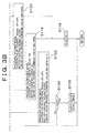
- Fig. 1 schematically shows an overall construction of a brake unit.
- hydraulic pressures are generated in two separate pressure chambers 2F, 2R of a master cylinder 2.
- a reservoir 3 is connected to the pressure chambers 2F, 2R of the master cylinder 2.
- a state of communication between the pressure chambers 2F, 2R and the reservoir 3 changes depending on the position of a piston in the master cylinder 2.
- the pressure chamber 2F of the master cylinder 2 is connected to wheel cylinders 6FL, 6FR constituting a brake mechanism for front-left and front-right wheels via a later-described brake actuator 100.
- the pressure chamber 2R of the master cylinder 2 is connected to wheel cylinders 6RL, 6RR constituting a brake mechanism for rear-left and rear-right wheels also via the brake actuator 100.
- a control valve 10F is provided in a pipe conduit 101F that constitutes a hydraulic system on the side of front wheels FR, FL and that connects the pressure chamber 2F to the wheel cylinders 6FL, 6FR.
- the control valve 10F has a linear valve port and a communication port.
- the linear valve port is provided with a linear valve mechanism capable of linearly controlling a hydraulic pressure by preventing pressure oil from flowing from the pressure chamber 2F toward the wheel cylinders 6FL, 6FR and adjusting flow of pressure oil from the wheel cylinders 6FL, 6FR toward the pressure chamber 2F.
- the control valve 10F is in communication with the pipe conduit 101F via the communication port.
- a control valve 10R is in communication with a pipe conduit 101R via the communication port.
- the linear valve port and the communication port can be switched over by a command from a control unit 200.
- a check valve 12F that allows pressure oil to flow toward the wheel cylinders 6FL, 6FR and that prevents pressure oil from flowing toward the pressure chamber 2F is provided in parallel with the control valve 10F.
- Pressure-holding valves 20FR, 20FL that can encapsulate pressure oil on the side of the wheel cylinders 6FL, 6FR when being closed are provided in the conduit 101F between the control valve 10F and the wheel cylinders 6FL, 6FR respectively.
- Check valves 22FR, 22FL that prevent pressure oil from flowing toward the wheel cylinders 6FL, 6FR are provided in parallel with the pressure-holding valves 20FR, 20FL respectively.
- a fluid pressure pump 30F that is rotationally driven by a motor M functions as a fluid pressure source in automatically controlling a braking force.
- a discharge port of the fluid pressure pump 30F is connected to the conduit 101F between the control valve 10F and the wheel cylinders 6FL, 6FR via an introduction duct 102F. Because of this pipe arrangement, the pressure oil that has been force-fed by the fluid pressure pump 30F can be supplied to the wheel cylinders 6FL, 6FR via the introduction ducts 102F, 101F respectively.
- the fluid pressure pump 30F is connected on the side of its suction port to an accumulator 40F via a pipe conduit 103F.
- Check valves 32F, 33F that prevent pressure oil from flowing in a counter-suction direction are disposed in the pipe conduit 103F.
- a check valve 31F that prevents pressure oil from flowing in a counter-discharge direction is provided in an introduction pipe conduit 102F connected to a discharge port of the fluid pressure pump 30F.
- the pipe conduit 103F between the check valves 32F, 33F is connected to the reservoir 3 via a suction pipe conduit 105.
- the suction pipe conduit 105 extends across a suction valve 50F capable of changing a state of communication of the suction pipe conduit 105.
- the suction valve 50F is constructed of an open-close valve that is opened and closed in response to an ON-OFF signal. By controlling the duty ratio of a control signal as the ON-OFF signal, the suction valve 50F is duty-driven in such a manner as to be opened and closed at intervals of a predetermined period.
- pipe conduit 101F and the suction pipe conduit 105 are connected by a pipe conduit 106F.
- the pipe conduit 106F is provided with a suction valve 52F that controls a state of predetermined oil that has been sucked from the pipe conduit 101F as a normal brake line.
- the pipe conduit 101F between the pressure-holding valves 20FR, 20FL and the wheel cylinders 6FL, 6FR and the accumulator 40F are connected by a pressure-reducing pipe conduit 104F.
- the pressure-reducing pipe conduit 104F is provided with pressure-reducing valves 60FR, 60FL that can reduce pressure in the wheel cylinders 6FL, 6FR by switching over the pressure-reducing pipe conduit 104F between its communication state and its shut-off state.
- a hydraulic system that is on the side of the rear wheels RR, RL and that is between the pressure chamber 2R and the wheel cylinders 6RL, 6RR is constructed in the same manner as the hydraulic system on the side of the front wheels FR, FL.
- reference symbols "F” annexed to the components on the side of the front wheels FR, FL are replaced by "R”, whereby corresponding components of the hydraulic system on the side of the rear wheels RR, RL are denoted. The description thereof will be omitted.
- the brake pedal 1 has a brake switch 4 that detects that the brake pedal 1 has been depressed to a predetermined position. Further, the pipe conduit 101R is provided with a master pressure sensor 5 that detects a hydraulic pressure generated in the master cylinder 2.
- the control unit 200 performs operation control of the brake actuator 100 that is composed of a pump and various valve gears.
- the control unit 200 is supplied with detection results from the brake switch 4, the master pressure sensor 5, a radar sensor 6 for detecting a vehicle-to-vehicle distance from a vehicle running in front and so on, wheel speed sensors 7 for detecting rotational speeds of the wheels, an acceleration sensor 8 for detecting a longitudinal acceleration applied to the vehicle, and so on.
- the control unit 200 is supplied with detection results from a yaw rate sensor for detecting a yaw rate, an accelerator pedal sensor for detecting a depression amount of an accelerator pedal, and shift position sensor for detecting a speed-change stage of a transmission.
- the control unit 200 performs ABS (anti-lock brake system) control for preventing the wheels from being locked, traction control for suppressing an accelerated slip tendency, VSC (vehicle stability control) control for suppressing a spin/drift-out tendency, BA (brake assist) control for generating a greater braking force at the time of emergency braking, vehicle-to-vehicle distance control for maintaining a predetermined vehicle-to-vehicle distance from a vehicle running in front, and so on. In accordance with various control processings, the control unit 200 performs operation control of the brake actuator 100.
- vehicle-to-vehicle distance control which is one of the control operations performed by the control unit 200, will be described using a flowchart shown in Fig. 3A and 3B and with reference to Figs. 1, 7.
- This vehicle-to-vehicle distance control is started if a predetermined condition for performance has been fulfilled, e.g., if constant-speed running control is being performed on an expressway or the like.
- "*" in the flowchart indicates either F or R and that "**" indicates one of FR, FL, RR, and RL.
- step 102 operation proceeds to step 102 where the control valves 10F, 10R are switched over to their linear valve ports to perform vehicle-to-vehicle distance control. Also, the pressure-holding valves 20FR, 20FL, 20RR, 20RL are opened, the pressure-reducing valves 60FR, 60FL, 60RR, 60RL are closed, and the suction valves 52F, 52R are closed. These valves are maintained in their respective positions until vehicle-to-vehicle distance control is terminated.
- step 104 an acceleration G that is obtained from a detection result of the acceleration sensor 8 and a vehicle-to-vehicle distance X that is obtained from a detection result of the radar sensor 6 are read.
- an evaluation function A is calculated based on the vehicle-to-vehicle distance X that has been read in step 104.
- Fig. 4 shows a relation between X and f(X).
- Fig. 5 shows a relation between dX/dt and g(dX/dt).
- step 108 if the result in step 108 is "YES", i.e., if the evaluation function A that has been calculated in step 106 assumes a value equal to or greater than the threshold As, operation proceeds to S110.
- S110 a brake requirement for applying brake automatically is made to indicate that a condition for operation of automatic brake has been fulfilled.
- step 112 a target vehicle acceleration Gm corresponding to the value of the evaluation function A that has been calculated in step 106 is set based on a map shown in Fig. 6.
- step 114 the target acceleration Gm that has been set in step 112 and the acceleration G that has been read in step 104 are compared with each other. If the detected acceleration G is smaller than the target acceleration Gm ("YES" in S114), operation proceeds to step 116.
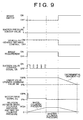
- step 116 control is performed in the pressure-increasing mode wherein hydraulic pressure supplied to the wheel cylinders 6FL, 6FR, 6RL, 6RR is increased.
- the suction valves 50F, 50R are open for an ON-level control signal SR, and are closed for an OFF-level control signal SR.
- a control signal SR having a prescribed ON-OFF pattern that changes with time is outputted.
- the suction valves 50F, 50R are duty-driven.
- the motor M for the hydraulic pumps 30F, 30R is duty-driven.
- a control signal Du indicating a duty ratio also has a prescribed pattern that changes with time. As shown in Fig.
- step 118 a flag F is set as 1.
- the present routine is then terminated. Accordingly, as long as the pressure-increasing mode has been established, processings of outputting the control signals SR, Du and the command value SM are also continued in the routines that follow.
- the suction valves 50F, 50R are duty-driven, whereby the amount of pressure oil to be sucked by the hydraulic pumps 30F, 30R is limited.
- the hydraulic pumps 30F, 30R are drivingly controlled at a low duty ratio.
- the hydraulic pumps 30F, 30R are drivingly controlled at a low duty ratio. Therefore, hydraulic pressure supplied to the wheel cylinders 6FL, 6FR, 6RL, 6RR can be prevented from rising unnecessarily.
- the hydraulic pumps 30F, 30R and the motor M are also used to perform other brake control operations for automatically controlling braking forces, such as ABS control, VSC control, and so on.
- braking forces are applied relatively gently.
- a fluid pressure pump that has a larger capacity than the hydraulic pumps and so on required by the control is controlled.
- such a control method is adopted as to limit the discharge amount of pressure oil individually based on both the amount of pressure oil sucked by the pump and the rotational speed of the pump motor.
- an increase in hydraulic pressure resulting from the occurrence of a malfunction can be suppressed effectively.
- step 120 control makes a transition to the pressure-holding mode (constant-pressure mode) wherein hydraulic pressure supplied to the wheel cylinders 6FL, 6FR, 6RL, 6RR is held constant.
- pressure oil is encapsulated between the hydraulic pumps 30F, 30R and the wheel cylinders 6FL, 6FR, 6RL, 6RR.
- hydraulic pressures in the wheel cylinders 6FL, 6FR, 6RL, 6RR are held constant. Because a control method of maintaining turned-off states of the hydraulic pumps 30F, 30R is adopted in the pressure-holding mode, an unnecessary rise in hydraulic pressure resulting from the occurrence of a malfunction, which may be caused while the hydraulic pumps 30F, 30R are in operation, can be prevented.
- step 108 If the result in step 108 has become "NO", i.e., if the evaluation function A calculated in step 106 has assumed a value smaller than the threshold
- step 122 a braking requirement is canceled.
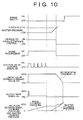
- step 132 control is performed in the pressure-reducing mode wherein hydraulic pressure supplied to the wheel cylinders 6FL, 6FR, 6RL, 6RR is reduced.
- the control signal SR for the suction valves are held on the OFF level to close the suction valves 50F, 50R.
- the opening command value SM decreases at the constant decremental gradient (-k1), whereby the linear valves (the control valves 10F, 10R) are opened gradually.
- the pressure oil that has been encapsulated between the hydraulic pumps 30F, 30R and the wheel cylinders 6FL, 6FR, 6RL, 6RR flows toward the master cylinder 2, and hydraulic pressure in the wheel cylinders 6FL, 6FR, 6RL, 6RR is reduced gradually. Because the hydraulic pumps 30F, 30R remain stopped during the pressure-reducing mode, an unnecessary rise in hydraulic pressure, which may be caused if operation control of the hydraulic pumps 30F, 30R has been performed, can be prevented.
- step 134 If the result in step 134 is "YES", i.e., if the count value T of the timer has become equal to or greater than the predetermined threshold Ts, operation proceeds to step 136.
- the flags F1, F2 are reset as 0, and the timer is reset for the next measurement.
- the threshold Ts has been predetermined as a period in which hydraulic pressure in the wheel cylinders 6FL, 6FR, 6RL, 6RR could be zero if the opening command value SM for the linear valves (the control valves 10F, 10R) has been reduced using the decremental gradient (-k1).
- the embodiment has been described as to brake control in the case where braking forces are applied to the four wheels. In the case of a two-wheel-drive vehicle, however, the embodiment can also be applied only to driven wheels, i.e., either front wheels or rear wheels.
- the second embodiment handles a process of terminating brake control to give priority to braking operation by a driver in the case where the driver has performed braking operation during brake control wherein braking forces are applied automatically as described in the first embodiment.
- this process will be described with reference to a flowchart shown in Fig. 8A and 8B.
- step 202 it is determined whether or not a hydraulic pressure P of the master cylinder 2 detected by the master pressure sensor 5 is greater than a threshold Pth. If the result in step 202 is "NO”, operation proceeds to step 204 where it is further determined whether or not the brake switch 4 has been turned on. If the result in step 204 is "NO”, braking operation by the driver has not been detected. The present routine is then terminated immediately. Namely, the already-described brake control shown in Fig. 3A and 3B is continued.
- step 202 and step 204 are "NO" and "YES” respectively, and operation proceeds to step 206.
- step 206 it is determined that a condition for interruption of the brake control shown in Fig. 3A and 3B has been fulfilled.
- the brake control shown in Fig. 3A and 3B is suspended immediately, and a control process shown in Fig. 8A and 8B is performed by priority.
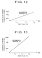
- step 210 an opening command value SMo for the linear valves constituting the control valves 10F, 10R is read.
- a timer value Tth2 corresponding to the opening command value SMo is set based on a map shown in Fig. 12.
- step 216 the same processing as in the aforementioned pressure-reducing mode is performed.
- the suction valve control signal SR is held on the OFF level to close the suction valves 50F, 50R.
- the linear valve opening command value SM is then outputted.
- step 218 the count value T2 of the timer is read.
- step 220 it is determined whether or not the count value T2 of the timer has exceeded the timer value Tth2 that has been set in step 212. If the result in step 220 is "NO", operation proceeds to the aforementioned step 216 where the same processing is repeated.
- the master cylinder 2 is in communication with the reservoir 3 that is at a pressure close to the atmospheric pressure. If the control valves 10F, 10R have been switched over to their communication ports immediately in such a circumstance, hydraulic pressures in the wheel cylinders 6FL, 6FR, 6RL, 6RR change immediately. This influence emerges as changes in deceleration and may cause a sense of incongruity to the driver.
- step 202 if the depression amount of the brake pedal 1 operated by the driver is great, the hydraulic pressure P in the master cylinder 2 may be increased to a pressure equal to or higher than the threshold Pth before the brake switch 4 is turned on. In such a case, the result in step 202 is "YES" and operation proceeds to step 230 where it is determined that a condition for interruption of the aforementioned brake control shown in Fig. 3A and 3B has been fulfilled.
- the brake control shown in Fig. 3A and 3B is suspended immediately, and the control process shown in Fig. 8A and 8B is performed by priority.
- an opening command value SMo for the linear valves constituting the control valves 10F, 10R is read.
- a timer value Tth1 corresponding to the opening command value SMo is set based on a map shown in Fig. 13.
- step 240 Operation then proceeds to step 240 where the same processing as in the aforementioned pressure-reducing mode is performed.
- the linear valve opening command value SM is then output.
- step 242 the count value T1 of the timer is read.
- step 244 it is determined whether or not the count value T1 of the timer has exceeded the timer value Tth1 that has been set in step 236. If the result in step 244 is "NO", operation proceeds to the aforementioned step 240 where the same processing is repeated.
- the master cylinder 2 has been shut off from the reservoir 3. If the control valves 10F, 10R have been switched over to their communication ports immediately in such a circumstance, hydraulic pressures in the wheel cylinders 6FL, 6FR, 6RL, 6RR are supplied to the master cylinder 2, so that the hydraulic pressure in the master cylinder 2 rises instantaneously. The vibrations generated at this moment are conveyed to the brake pedal 1 and cause a sense of incongruity to the driver who is performing braking operation.
- the hydraulic pressure P in the master cylinder 2 may increase to a pressure equal to or higher than the threshold Pth after the brake switch 4 has been turned on.
- the flowchart shown in Fig. 8A and 8B is also applied directly to this case. That is, if the brake switch 4 has been turned on (if the result in step 202 is "NO” and if the result in step 204 is "YES"), the processing in step 216 using the relatively gentle decremental gradient (-k3) is performed repeatedly.
- step 240 using the relatively great decremental gradient (-k2) is started.
- the linear valves constituting the control valves 10F, 10R are constructed for example of valve gears having needle valves with a controllable valve opening.
- the linear valves can also be constructed of open-close valves that are opened and closed in response to ON/OFF signals. In this case, the ON/OFF operation is duty-driven, whereby the differential pressure therebetween can be controlled.
- suction valves 50F, 50R are exemplified as open-close valves that are opened and closed in response to ON/OFF signals, they may also be constructed of valve gears with a controllable valve opening.
- the brake switch 4 and the master pressure sensor 5 are exemplified as mechanisms for detecting braking operation by the driver, it is also possible to additionally employ a stroke sensor for detecting a stroke of the brake pedal, a sensor or a switch for detecting a depressing force, and so on.
- the vehicular brake control apparatus adopts a construction wherein the pressure-increasing gradient of operating fluid is controlled by controlling both a pressure-increasing pump and a fluid pressure adjuster for adjusting a pressure of operating fluid force-fed from the pump.
- the pressure-increasing gradient of operating fluid is controlled by controlling both a pressure-increasing pump and a fluid pressure adjuster for adjusting a pressure of operating fluid force-fed from the pump.
- the vehicular brake control apparatus adopts a construction wherein operating fluid that has been force-fed from the pump is introduced into the communication passages between the control valves and the brakes, wherein the control valves are closed during pressure-holding control for holding fluid pressures in the brakes, and wherein the controller for stopping operation of the pump is provided.
- the vehicular brake control apparatus adopts a construction wherein operating fluid that has been force-fed from the pump is introduced into the communication passages between the control valves and the brakes, wherein the control valves are opened during pressure-reducing control for reducing fluid pressures in the brakes, and wherein the controller for stopping operation of the pump is provided.
- pressure-reducing control is performed by stopping the pump and opening the control valves, an unnecessary rise in fluid pressures in the brakes can be prevented.
- the controller 200 is implemented as a programmed general purpose computer. It will be appreciated by those skilled in the art that the controller can be implemented using a single special purpose integrated circuit (e.g., ASIC) having a main or central processor section for overall, system-level control, and separate sections dedicated to performing various different specific computations, functions and other processes under control of the central processor section.
- the controller can be a plurality of separate dedicated or programmable integrated or other electronic circuits or devices (e.g., hardwired electronic or logic circuits such as discrete element circuits, or programmable logic devices such as PLDs, PLAs, PALs or the like).
- the controller can be implemented using a suitably programmed general purpose computer, e.g., a microprocessor, microcontroller or other processor device (CPU or MPU), either alone or in conjunction with one or more peripheral (e.g., integrated circuit) data and signal processing devices.
- a suitably programmed general purpose computer e.g., a microprocessor, microcontroller or other processor device (CPU or MPU)
- CPU or MPU processor device
- peripheral e.g., integrated circuit
- a distributed processing architecture can be used for maximum data/signal processing capability and speed.
Landscapes
- Engineering & Computer Science (AREA)
- Physics & Mathematics (AREA)
- Transportation (AREA)
- Mechanical Engineering (AREA)
- Fluid Mechanics (AREA)
- Electromagnetism (AREA)
- Regulating Braking Force (AREA)
- Control Of Driving Devices And Active Controlling Of Vehicle (AREA)
- Braking Systems And Boosters (AREA)
Abstract
Description
Claims (11)
- A vehicular brake control apparatus having brakes (6FL, 6FR, 6RL, 6RR) that apply braking forces corresponding to a pressure of a supplied operating fluid to wheels, a pump (30F, 30R) that force-feeds the operating fluid, and a valve (50F, 50R) that adjusts the pressure of the operating fluid that is force-fed from the pump (30F, 30R), the contol apparatus characterized by comprising:a control means (200) for performing an operation control of the pump (30F, 30R) and the valve (50F, 50R) to control the pressure of the operating fluid to be supplied to the brakes (6FL, 6FR, 6RL, 6RR) when the control means (200, S108, S110) determines that the braking forces are to be applied to the vehicle,in that the control means (200, S116) controls a pressure-increasing gradient of a fluid pressure by controlling both the pump (30F, 30R) and the valve (50F, 50R) during a pressure-increasing control for increasing the pressure in the brakes (6FL, 6FR, 6RL, 6RR).
- The control apparatus according to claim 1, characterized in that:the valve (50F, 50R) is connected to a suction port of the pump (30F, 30R) and adjusts the pressure of the operating fluid to be force-fed from the pump (30F, 30R) by controlling an amount of the operating fluid to be supplied to the pump (30F, 30R).
- The control apparatus according to claim 1 or 2, characterized in that:the control means (200, S116) controls the pressure-increasing gradient of the fluid pressure by performing a duty-driving operation of the pump (30F, 30R) and a duty-driving operation of the opening and closing of the valve (50F, 50R) during the pressure-increasing control.
- The control apparatus according to any one of claims 1 to 3,
characterized in that:the control means (S108) determines that braking forces are to be applied to the vehicle, if a vehicle-to-vehicle distance from another vehicle running in front satisfies a predetermined condition. - The control apparatus according to any one of claims 1 to 4,
characterized by further comprising:a master cylinder (2) that changes the pressure of the operating fluid in accordance with a brake operating force;control valves (10F, 10R) provided in communication passages (101F, 101R) between the master cylinder (2) and the brakes (6FL, 6FR, 6RL, 6RR) to control the opening state of the communication passages (101F, 101R); andan introduction passage (102F, 102R) that introduces the operating fluid that has been force-fed from the pump (30F, 30R) into the communication passages (101F, 101R) between the control valves (10F, 10R) and the brakes (6FL, 6FR, 6RL, 6RR),in that the control means (200, S202, S204, S206, S216, S230, S240) suspends the pressure-increasing gradient control of the fluid pressure, opens the control valves (10F, 10R), and stops the operation of the pump (30F, 30R) if the braking operation has been indicated by the driver. - The control apparatus according to claim 5, characterized in that:the control means (200, S202, S204, S206, S216, S230, S240) changes an opening speed of the control valves (10F, 10R) in accordance with a hydraulic pressure in the master cylinder (2) if the braking operation has been indicated by a driver.
- A vehicular brake control apparatus having a master cylinder (2) that changes a pressure of an operating fluid in accordance with a brake operating force, brakes (6FL, 6FR, 6RL, 6RR) that apply the brake operating force corresponding to the pressure of the operating fluid supplied from the master cylinder (2) to wheels, a pump (30F, 30R) that force-feeds the operating fluid, control valves (10F, 10R) provided in communication passages (101F, 101R) between the master cylinder (2) and the brakes (6FL, 6FR, 6RL, 6RR) to control an opening state of the communication passages (101F, 101R), and an introduction passage (102F, 102R) that introduces the operating fluid that has been force-fed from the pump (30F, 30R) to the communication passages (101F, 101R) between the control valves (10F, 10R) and the brakes (6FL, 6FR, 6RL, 6RR), the control apparatus characterized by comprising:a control means (200) for performing an operation control of the pump (30F, 30R) and the control valves (10F, 10R) to control the pressure of the operating fluid to be supplied to the brakes (6FL, 6FR, 6RL, 6RR) when the control means (S108, S110) determines that the braking forces are to be applied to the vehicle,in that the control means (200, S120) closes the control valves and stops the operation of the pump (30F, 30R) during a pressure-holding control for holding the operating fluid pressure in the brakes (6FL, 6FR, 6RL, 6RR).
- The control apparatus according to claim 7, characterized in that:the control means (200, S202, S204, S206, S216, S230, S240) opens the control valves (10F, 10R) and maintains a stopped state of operation of the pump (30F, 30R) if the braking operation has been indicated by a driver.
- A brake control apparatus for a vheicle having a master cylinder (2) that changes a pressure of an operating fluid in accordance with a brake operating force, brakes (6FL, 6FR, 6RL, 6RR) that apply the brake operating force corresponding to the pressure of the operating fluid supplied from the master cylinder (2) to wheels, a pump (30F, 30R) that force-feeds the operating fluid, control valves (10F, 10R) provided in communication passages (101F, 101R) between the master cylinder (2) and the brakes (6FL, 6FR, 6RL, 6RR) to control an opening state of the communication passages (102F, 102R), and an introduction passage (102F, 102R) that introduces the operating fluid that has been force-fed from the pump (30F, 30R) into the communication passages (102F, 102R) between the control valves (10F, 10R) and the brakes (6FL, 6FR, 6RL, 6RR), the control appratus characterized by comprising:a control means (200) for performing an operation control of the pump (30F, 30R) and the control valves (10F, 10R) to control the pressure of the operating fluid to be supplied to the brakes (6FL, 6FR, 6RL, 6RR) when the control means (S108, S110) determines that the braking forces are to be applied to the vehicle,in that the control means (200, S132) opens the control valves (10F, 10R) and stops the operation of the pump (30F, 30R) during a pressure-reducing control for reducing the operating fluid pressure in the brakes (6FL, 6FR, 6RL, 6RR).
- The control apparatus according to claim 11, characterized in that:the control means (200, S202, S204, S206, S216, S230, S240) changes an opening speed of the control valves (10F, 10R) in accordance with a hydraulic pressure in the master cylinder if the braking operation has been indicated by a driver.
- The control apparatus according to any one of claims 1 to 10,
characterized in that:the control means (200) selects one of a pressure-increasing control mode, a pressure-reducing control mode, and a pressure-holding mode in accordance with a vehicle-to-vehicle distance from another vehicle running in front and an acceleration of the vehicle and controls the fluid pressure in the brakes in the selected mode.
Applications Claiming Priority (2)
| Application Number | Priority Date | Filing Date | Title |
|---|---|---|---|
| JP2000237456A JP3651372B2 (en) | 2000-08-04 | 2000-08-04 | Brake control device for vehicle |
| JP2000237456 | 2000-08-04 |
Publications (3)
| Publication Number | Publication Date |
|---|---|
| EP1177960A2 true EP1177960A2 (en) | 2002-02-06 |
| EP1177960A3 EP1177960A3 (en) | 2003-09-17 |
| EP1177960B1 EP1177960B1 (en) | 2005-10-26 |
Family
ID=18729315
Family Applications (1)
| Application Number | Title | Priority Date | Filing Date |
|---|---|---|---|
| EP01118925A Expired - Lifetime EP1177960B1 (en) | 2000-08-04 | 2001-08-03 | Vehicular brake control apparatus |
Country Status (4)
| Country | Link |
|---|---|
| US (1) | US6582034B2 (en) |
| EP (1) | EP1177960B1 (en) |
| JP (1) | JP3651372B2 (en) |
| DE (1) | DE60114316T2 (en) |
Cited By (3)
| Publication number | Priority date | Publication date | Assignee | Title |
|---|---|---|---|---|
| WO2009031009A1 (en) * | 2007-09-04 | 2009-03-12 | Toyota Jidosha Kabushiki Kaisha | Brake apparatus and method for controlling the brake apparatus |
| GB2555881A (en) * | 2017-06-09 | 2018-05-16 | Liberty Vehicle Tech Limited | Fluidic control system |
| US11619244B2 (en) | 2017-06-09 | 2023-04-04 | Liberty Vehicle Technologies Limited | Fluidic control system |
Families Citing this family (10)
| Publication number | Priority date | Publication date | Assignee | Title |
|---|---|---|---|---|
| JP2003285726A (en) * | 2002-03-26 | 2003-10-07 | Robert Bosch Gmbh | Method of controlling brake pressure acting on wheel brake and brake device |
| DE10232792A1 (en) * | 2002-07-19 | 2004-02-12 | Wabco Gmbh & Co. Ohg | Braking method for a vehicle |
| JP4276485B2 (en) | 2003-08-18 | 2009-06-10 | 株式会社日立製作所 | Vehicle attitude control device |
| US20070142884A1 (en) * | 2005-12-16 | 2007-06-21 | Acoustx Corporation | Methods and apparatuses for treating an esophageal disorder such as gastroesophageal reflux disease |
| DE102005060321A1 (en) * | 2005-12-16 | 2007-06-21 | Robert Bosch Gmbh | Method and device for reducible production of a predefinable final pressure in a brake system |
| US7475953B2 (en) * | 2006-02-03 | 2009-01-13 | Kelsey-Hayes Company | Soft-stop braking control |
| JP5024515B2 (en) * | 2006-06-28 | 2012-09-12 | 株式会社アドヴィックス | Brake fluid pressure control device for vehicle |
| JP5103924B2 (en) | 2007-02-09 | 2012-12-19 | 株式会社アドヴィックス | Vehicle motion control device |
| JP4769233B2 (en) * | 2007-06-29 | 2011-09-07 | 日信工業株式会社 | Brake hydraulic pressure control device for vehicles |
| US10106137B2 (en) * | 2017-01-06 | 2018-10-23 | Ford Global Technologies, Llc | Adjustment of maximum brake pump speed based on rate of change of target deceleration |
Citations (1)
| Publication number | Priority date | Publication date | Assignee | Title |
|---|---|---|---|---|
| JPH11321619A (en) | 1998-03-31 | 1999-11-24 | Robert Bosch Gmbh | Apparatus and method for controlling at least one driving dynamic variable of a vehicle |
Family Cites Families (29)
| Publication number | Priority date | Publication date | Assignee | Title |
|---|---|---|---|---|
| JPS6035646A (en) * | 1983-08-09 | 1985-02-23 | Nippon Denso Co Ltd | Antiskid controller |
| DE3418520A1 (en) | 1984-05-18 | 1985-11-21 | Teves Gmbh Alfred | SLIP-CONTROLLED BRAKE SYSTEM FOR ROAD VEHICLES WITH ALL-WHEEL DRIVE |
| JP2717251B2 (en) * | 1988-02-09 | 1998-02-18 | マツダ株式会社 | Anti-lock device |
| DE4010411A1 (en) * | 1990-03-31 | 1991-10-02 | Bosch Gmbh Robert | HYDRAULIC TWO-CIRCUIT BRAKE SYSTEM |
| FR2669883B1 (en) * | 1990-11-29 | 1993-01-29 | Bendix Europ Services Tech | AUTOMATIC BRAKING DEVICE FOR VEHICLE. |
| DE4134427A1 (en) * | 1991-10-18 | 1993-04-22 | Teves Gmbh Alfred | BLOCK-PROTECTED HYDRAULIC BRAKE SYSTEM |
| US5358320A (en) * | 1992-02-28 | 1994-10-25 | Atsugi Unisia Corporation | Anti-skid brake control system for automotive vehicles |
| DE4214685A1 (en) * | 1992-05-02 | 1993-11-04 | Teves Gmbh Alfred | CIRCUIT ARRANGEMENT FOR A BRAKE SYSTEM WITH DRIVE-SLIP CONTROL |
| DE4317760A1 (en) * | 1993-05-28 | 1994-12-01 | Teves Gmbh Alfred | Brake system for motor vehicles with a device for regulating both the brake and the drive slip |
| JPH0858553A (en) * | 1994-08-26 | 1996-03-05 | Nippondenso Co Ltd | Brake pressure control device for vehicle |
| JP3612745B2 (en) * | 1994-09-20 | 2005-01-19 | 株式会社デンソー | Vehicle motion characteristic control device |
| DE4438721A1 (en) * | 1994-10-29 | 1996-05-02 | Teves Gmbh Alfred | Hydraulic skid-control braking system for motor vehicle with ASR |
| DE4440517B4 (en) | 1994-11-12 | 2004-04-15 | Robert Bosch Gmbh | Method and device for controlling a return pump |
| WO1996015926A1 (en) * | 1994-11-24 | 1996-05-30 | Robert Bosch Gmbh | Electromagnetic valve arrangement |
| JP3138603B2 (en) * | 1994-11-30 | 2001-02-26 | 三菱電機株式会社 | Anti-skid control device |
| DE19501760B4 (en) * | 1995-01-21 | 2005-11-03 | Robert Bosch Gmbh | Method and device for controlling an ABS / ASR system |
| US5609401A (en) * | 1995-02-21 | 1997-03-11 | General Motors Corporation | Proportional braking system with dual poppet valves |
| US5683149A (en) * | 1995-04-05 | 1997-11-04 | Toyota Jidosha Kabushiki Kaisha | Hydraulic pressure control apparatus having device for estimating amount of fluid in reservoir to which the fluid is discharged to reduce cylinder pressure |
| JPH0948335A (en) * | 1995-08-09 | 1997-02-18 | Akebono Brake Ind Co Ltd | Antilock hydraulic control device |
| DE19529363A1 (en) * | 1995-08-10 | 1997-02-13 | Bosch Gmbh Robert | Controllable valve |
| DE19601268A1 (en) * | 1996-01-16 | 1997-07-17 | Teves Gmbh Alfred | Hydraulic brake system with traction control |
| DE19615449B4 (en) * | 1996-04-19 | 2009-12-31 | Robert Bosch Gmbh | Method and device for controlling the brake system of a vehicle |
| DE19625919B4 (en) * | 1996-06-28 | 2007-12-13 | Robert Bosch Gmbh | System for controlling the braking effect in a motor vehicle |
| JPH1067311A (en) * | 1996-08-27 | 1998-03-10 | Aisin Seiki Co Ltd | Wheel brake fluid pressure control device |
| DE19712889A1 (en) * | 1997-03-27 | 1998-10-01 | Bosch Gmbh Robert | Method and device for determining a quantity describing the system pressure in a brake circuit |
| JPH1134860A (en) * | 1997-07-23 | 1999-02-09 | Jidosha Kiki Co Ltd | Abnormality detector and safety device for hydraulic brake booster |
| EP1077847B1 (en) * | 1998-05-12 | 2003-03-05 | Continental Teves AG & Co. oHG | Hydraulic brake system for regulated and comfortable braking |
| EP0965477B2 (en) * | 1998-06-18 | 2007-01-03 | Nissan Motor Company, Limited | Apparatus and method for cruise control with regulation of vehicle spacing |
| WO2000002753A2 (en) * | 1998-07-09 | 2000-01-20 | Continental Teves Ag & Co. Ohg | Method and device for adjusting brake pressure and for opening an inlet valve |
-
2000
- 2000-08-04 JP JP2000237456A patent/JP3651372B2/en not_active Expired - Fee Related
-
2001
- 2001-07-30 US US09/916,283 patent/US6582034B2/en not_active Expired - Fee Related
- 2001-08-03 EP EP01118925A patent/EP1177960B1/en not_active Expired - Lifetime
- 2001-08-03 DE DE60114316T patent/DE60114316T2/en not_active Expired - Fee Related
Patent Citations (1)
| Publication number | Priority date | Publication date | Assignee | Title |
|---|---|---|---|---|
| JPH11321619A (en) | 1998-03-31 | 1999-11-24 | Robert Bosch Gmbh | Apparatus and method for controlling at least one driving dynamic variable of a vehicle |
Cited By (6)
| Publication number | Priority date | Publication date | Assignee | Title |
|---|---|---|---|---|
| WO2009031009A1 (en) * | 2007-09-04 | 2009-03-12 | Toyota Jidosha Kabushiki Kaisha | Brake apparatus and method for controlling the brake apparatus |
| CN101557972B (en) * | 2007-09-04 | 2013-03-27 | 丰田自动车株式会社 | Method for controlling brake apparatus |
| US8506022B2 (en) | 2007-09-04 | 2013-08-13 | Toyota Jidosha Kabushiki Kaisha | Brake apparatus and method for controlling the brake apparatus |
| GB2555881A (en) * | 2017-06-09 | 2018-05-16 | Liberty Vehicle Tech Limited | Fluidic control system |
| GB2555881B (en) * | 2017-06-09 | 2018-10-24 | Liberty Vehicle Tech Limited | Fluidic control system |
| US11619244B2 (en) | 2017-06-09 | 2023-04-04 | Liberty Vehicle Technologies Limited | Fluidic control system |
Also Published As
| Publication number | Publication date |
|---|---|
| JP3651372B2 (en) | 2005-05-25 |
| DE60114316D1 (en) | 2005-12-01 |
| JP2002046588A (en) | 2002-02-12 |
| US20020021044A1 (en) | 2002-02-21 |
| US6582034B2 (en) | 2003-06-24 |
| EP1177960A3 (en) | 2003-09-17 |
| EP1177960B1 (en) | 2005-10-26 |
| DE60114316T2 (en) | 2006-07-27 |
Similar Documents
| Publication | Publication Date | Title |
|---|---|---|
| KR100374091B1 (en) | Method and apparatus for controlling an anti-braking system and an anti-slip regulation system | |
| EP1177960B1 (en) | Vehicular brake control apparatus | |
| US6880900B2 (en) | Brake control system and method for vehicle | |
| EP0919444B1 (en) | Brake force control device | |
| EP1125809B1 (en) | Vehicular brake control apparatus and vehicular brake control method | |
| US6349995B1 (en) | Brake control system for a vehicle | |
| JPH06206532A (en) | Hydraulic vehicle brake system with skid control device | |
| JP4013314B2 (en) | Electronically controlled brake device for vehicles | |
| US5249849A (en) | Anti-skid control system for a part time four-wheel drive vehicle | |
| JP3651373B2 (en) | Brake control device for vehicle | |
| US6961649B2 (en) | Vehicle motion control apparatus | |
| EP0803421B1 (en) | Brake apparatus for a vehicle | |
| EP0738638B1 (en) | Hydraulic braking pressure control system for an automotive vehicle | |
| US6863355B2 (en) | Brake control device for a vehicle | |
| JP4389294B2 (en) | Brake control device for vehicle | |
| US6533368B2 (en) | Vehicle motion control system | |
| US5700069A (en) | Anti-skid control system for an automotive vehicle | |
| US6422660B2 (en) | Brake control system for a vehicle | |
| EP0503873B1 (en) | Braking system for vehicle | |
| US6120112A (en) | Brake pressure control device for vehicle | |
| JP3885361B2 (en) | Brake control device for vehicle | |
| US5971502A (en) | Secondary braking control | |
| JP3769969B2 (en) | Abnormality detection method for vehicle braking force control device | |
| JP2756507B2 (en) | Vehicle traction control method | |
| JP4089042B2 (en) | Brake control device for vehicle |
Legal Events
| Date | Code | Title | Description |
|---|---|---|---|
| PUAI | Public reference made under article 153(3) epc to a published international application that has entered the european phase |
Free format text: ORIGINAL CODE: 0009012 |
|
| 17P | Request for examination filed |
Effective date: 20010903 |
|
| AK | Designated contracting states |
Kind code of ref document: A2 Designated state(s): AT BE CH CY DE DK ES FI FR GB GR IE IT LI LU MC NL PT SE TR |
|
| AX | Request for extension of the european patent |
Free format text: AL;LT;LV;MK;RO;SI |
|
| PUAL | Search report despatched |
Free format text: ORIGINAL CODE: 0009013 |
|
| AK | Designated contracting states |
Kind code of ref document: A3 Designated state(s): AT BE CH CY DE DK ES FI FR GB GR IE IT LI LU MC NL PT SE TR |
|
| AX | Request for extension of the european patent |
Extension state: AL LT LV MK RO SI |
|
| 17Q | First examination report despatched |
Effective date: 20031202 |
|
| AKX | Designation fees paid |
Designated state(s): DE FR GB |
|
| GRAP | Despatch of communication of intention to grant a patent |
Free format text: ORIGINAL CODE: EPIDOSNIGR1 |
|
| GRAS | Grant fee paid |
Free format text: ORIGINAL CODE: EPIDOSNIGR3 |
|
| GRAA | (expected) grant |
Free format text: ORIGINAL CODE: 0009210 |
|
| AK | Designated contracting states |
Kind code of ref document: B1 Designated state(s): DE FR GB |
|
| REG | Reference to a national code |
Ref country code: GB Ref legal event code: FG4D |
|
| REF | Corresponds to: |
Ref document number: 60114316 Country of ref document: DE Date of ref document: 20051201 Kind code of ref document: P |
|
| ET | Fr: translation filed | ||
| PLBE | No opposition filed within time limit |
Free format text: ORIGINAL CODE: 0009261 |
|
| STAA | Information on the status of an ep patent application or granted ep patent |
Free format text: STATUS: NO OPPOSITION FILED WITHIN TIME LIMIT |
|
| 26N | No opposition filed |
Effective date: 20060727 |
|
| PGFP | Annual fee paid to national office [announced via postgrant information from national office to epo] |
Ref country code: DE Payment date: 20080814 Year of fee payment: 8 |
|
| PGFP | Annual fee paid to national office [announced via postgrant information from national office to epo] |
Ref country code: FR Payment date: 20080818 Year of fee payment: 8 |
|
| PGFP | Annual fee paid to national office [announced via postgrant information from national office to epo] |
Ref country code: GB Payment date: 20080813 Year of fee payment: 8 |
|
| GBPC | Gb: european patent ceased through non-payment of renewal fee |
Effective date: 20090803 |
|
| REG | Reference to a national code |
Ref country code: FR Ref legal event code: ST Effective date: 20100430 |
|
| PG25 | Lapsed in a contracting state [announced via postgrant information from national office to epo] |
Ref country code: FR Free format text: LAPSE BECAUSE OF NON-PAYMENT OF DUE FEES Effective date: 20090831 Ref country code: DE Free format text: LAPSE BECAUSE OF NON-PAYMENT OF DUE FEES Effective date: 20100302 |
|
| PG25 | Lapsed in a contracting state [announced via postgrant information from national office to epo] |
Ref country code: GB Free format text: LAPSE BECAUSE OF NON-PAYMENT OF DUE FEES Effective date: 20090803 |