EP1177929A2 - Torque transmission device - Google Patents
Torque transmission device Download PDFInfo
- Publication number
- EP1177929A2 EP1177929A2 EP01118273A EP01118273A EP1177929A2 EP 1177929 A2 EP1177929 A2 EP 1177929A2 EP 01118273 A EP01118273 A EP 01118273A EP 01118273 A EP01118273 A EP 01118273A EP 1177929 A2 EP1177929 A2 EP 1177929A2
- Authority
- EP
- European Patent Office
- Prior art keywords
- helical gear
- gear
- axis
- cos
- shaft
- Prior art date
- Legal status (The legal status is an assumption and is not a legal conclusion. Google has not performed a legal analysis and makes no representation as to the accuracy of the status listed.)
- Withdrawn
Links
Images


Classifications
-
- F—MECHANICAL ENGINEERING; LIGHTING; HEATING; WEAPONS; BLASTING
- F16—ENGINEERING ELEMENTS AND UNITS; GENERAL MEASURES FOR PRODUCING AND MAINTAINING EFFECTIVE FUNCTIONING OF MACHINES OR INSTALLATIONS; THERMAL INSULATION IN GENERAL
- F16H—GEARING
- F16H1/00—Toothed gearings for conveying rotary motion
- F16H1/02—Toothed gearings for conveying rotary motion without gears having orbital motion
- F16H1/20—Toothed gearings for conveying rotary motion without gears having orbital motion involving more than two intermeshing members
-
- B—PERFORMING OPERATIONS; TRANSPORTING
- B60—VEHICLES IN GENERAL
- B60K—ARRANGEMENT OR MOUNTING OF PROPULSION UNITS OR OF TRANSMISSIONS IN VEHICLES; ARRANGEMENT OR MOUNTING OF PLURAL DIVERSE PRIME-MOVERS IN VEHICLES; AUXILIARY DRIVES FOR VEHICLES; INSTRUMENTATION OR DASHBOARDS FOR VEHICLES; ARRANGEMENTS IN CONNECTION WITH COOLING, AIR INTAKE, GAS EXHAUST OR FUEL SUPPLY OF PROPULSION UNITS IN VEHICLES
- B60K6/00—Arrangement or mounting of plural diverse prime-movers for mutual or common propulsion, e.g. hybrid propulsion systems comprising electric motors and internal combustion engines
- B60K6/20—Arrangement or mounting of plural diverse prime-movers for mutual or common propulsion, e.g. hybrid propulsion systems comprising electric motors and internal combustion engines the prime-movers consisting of electric motors and internal combustion engines, e.g. HEVs
- B60K6/22—Arrangement or mounting of plural diverse prime-movers for mutual or common propulsion, e.g. hybrid propulsion systems comprising electric motors and internal combustion engines the prime-movers consisting of electric motors and internal combustion engines, e.g. HEVs characterised by apparatus, components or means specially adapted for HEVs
- B60K6/36—Arrangement or mounting of plural diverse prime-movers for mutual or common propulsion, e.g. hybrid propulsion systems comprising electric motors and internal combustion engines the prime-movers consisting of electric motors and internal combustion engines, e.g. HEVs characterised by apparatus, components or means specially adapted for HEVs characterised by the transmission gearings
-
- B—PERFORMING OPERATIONS; TRANSPORTING
- B60—VEHICLES IN GENERAL
- B60K—ARRANGEMENT OR MOUNTING OF PROPULSION UNITS OR OF TRANSMISSIONS IN VEHICLES; ARRANGEMENT OR MOUNTING OF PLURAL DIVERSE PRIME-MOVERS IN VEHICLES; AUXILIARY DRIVES FOR VEHICLES; INSTRUMENTATION OR DASHBOARDS FOR VEHICLES; ARRANGEMENTS IN CONNECTION WITH COOLING, AIR INTAKE, GAS EXHAUST OR FUEL SUPPLY OF PROPULSION UNITS IN VEHICLES
- B60K6/00—Arrangement or mounting of plural diverse prime-movers for mutual or common propulsion, e.g. hybrid propulsion systems comprising electric motors and internal combustion engines
- B60K6/20—Arrangement or mounting of plural diverse prime-movers for mutual or common propulsion, e.g. hybrid propulsion systems comprising electric motors and internal combustion engines the prime-movers consisting of electric motors and internal combustion engines, e.g. HEVs
- B60K6/42—Arrangement or mounting of plural diverse prime-movers for mutual or common propulsion, e.g. hybrid propulsion systems comprising electric motors and internal combustion engines the prime-movers consisting of electric motors and internal combustion engines, e.g. HEVs characterised by the architecture of the hybrid electric vehicle
- B60K6/46—Series type
-
- F—MECHANICAL ENGINEERING; LIGHTING; HEATING; WEAPONS; BLASTING
- F16—ENGINEERING ELEMENTS AND UNITS; GENERAL MEASURES FOR PRODUCING AND MAINTAINING EFFECTIVE FUNCTIONING OF MACHINES OR INSTALLATIONS; THERMAL INSULATION IN GENERAL
- F16H—GEARING
- F16H57/00—General details of gearing
- F16H57/02—Gearboxes; Mounting gearing therein
- F16H57/021—Shaft support structures, e.g. partition walls, bearing eyes, casing walls or covers with bearings
-
- B—PERFORMING OPERATIONS; TRANSPORTING
- B60—VEHICLES IN GENERAL
- B60K—ARRANGEMENT OR MOUNTING OF PROPULSION UNITS OR OF TRANSMISSIONS IN VEHICLES; ARRANGEMENT OR MOUNTING OF PLURAL DIVERSE PRIME-MOVERS IN VEHICLES; AUXILIARY DRIVES FOR VEHICLES; INSTRUMENTATION OR DASHBOARDS FOR VEHICLES; ARRANGEMENTS IN CONNECTION WITH COOLING, AIR INTAKE, GAS EXHAUST OR FUEL SUPPLY OF PROPULSION UNITS IN VEHICLES
- B60K1/00—Arrangement or mounting of electrical propulsion units
- B60K1/02—Arrangement or mounting of electrical propulsion units comprising more than one electric motor
-
- Y—GENERAL TAGGING OF NEW TECHNOLOGICAL DEVELOPMENTS; GENERAL TAGGING OF CROSS-SECTIONAL TECHNOLOGIES SPANNING OVER SEVERAL SECTIONS OF THE IPC; TECHNICAL SUBJECTS COVERED BY FORMER USPC CROSS-REFERENCE ART COLLECTIONS [XRACs] AND DIGESTS
- Y02—TECHNOLOGIES OR APPLICATIONS FOR MITIGATION OR ADAPTATION AGAINST CLIMATE CHANGE
- Y02T—CLIMATE CHANGE MITIGATION TECHNOLOGIES RELATED TO TRANSPORTATION
- Y02T10/00—Road transport of goods or passengers
- Y02T10/60—Other road transportation technologies with climate change mitigation effect
- Y02T10/62—Hybrid vehicles
-
- Y—GENERAL TAGGING OF NEW TECHNOLOGICAL DEVELOPMENTS; GENERAL TAGGING OF CROSS-SECTIONAL TECHNOLOGIES SPANNING OVER SEVERAL SECTIONS OF THE IPC; TECHNICAL SUBJECTS COVERED BY FORMER USPC CROSS-REFERENCE ART COLLECTIONS [XRACs] AND DIGESTS
- Y10—TECHNICAL SUBJECTS COVERED BY FORMER USPC
- Y10S—TECHNICAL SUBJECTS COVERED BY FORMER USPC CROSS-REFERENCE ART COLLECTIONS [XRACs] AND DIGESTS
- Y10S903/00—Hybrid electric vehicles, HEVS
- Y10S903/902—Prime movers comprising electrical and internal combustion motors
- Y10S903/903—Prime movers comprising electrical and internal combustion motors having energy storing means, e.g. battery, capacitor
- Y10S903/904—Component specially adapted for hev
- Y10S903/909—Gearing
-
- Y—GENERAL TAGGING OF NEW TECHNOLOGICAL DEVELOPMENTS; GENERAL TAGGING OF CROSS-SECTIONAL TECHNOLOGIES SPANNING OVER SEVERAL SECTIONS OF THE IPC; TECHNICAL SUBJECTS COVERED BY FORMER USPC CROSS-REFERENCE ART COLLECTIONS [XRACs] AND DIGESTS
- Y10—TECHNICAL SUBJECTS COVERED BY FORMER USPC
- Y10T—TECHNICAL SUBJECTS COVERED BY FORMER US CLASSIFICATION
- Y10T74/00—Machine element or mechanism
- Y10T74/19—Gearing
- Y10T74/19628—Pressure distributing
-
- Y—GENERAL TAGGING OF NEW TECHNOLOGICAL DEVELOPMENTS; GENERAL TAGGING OF CROSS-SECTIONAL TECHNOLOGIES SPANNING OVER SEVERAL SECTIONS OF THE IPC; TECHNICAL SUBJECTS COVERED BY FORMER USPC CROSS-REFERENCE ART COLLECTIONS [XRACs] AND DIGESTS
- Y10—TECHNICAL SUBJECTS COVERED BY FORMER USPC
- Y10T—TECHNICAL SUBJECTS COVERED BY FORMER US CLASSIFICATION
- Y10T74/00—Machine element or mechanism
- Y10T74/19—Gearing
- Y10T74/19642—Directly cooperating gears
-
- Y—GENERAL TAGGING OF NEW TECHNOLOGICAL DEVELOPMENTS; GENERAL TAGGING OF CROSS-SECTIONAL TECHNOLOGIES SPANNING OVER SEVERAL SECTIONS OF THE IPC; TECHNICAL SUBJECTS COVERED BY FORMER USPC CROSS-REFERENCE ART COLLECTIONS [XRACs] AND DIGESTS
- Y10—TECHNICAL SUBJECTS COVERED BY FORMER USPC
- Y10T—TECHNICAL SUBJECTS COVERED BY FORMER US CLASSIFICATION
- Y10T74/00—Machine element or mechanism
- Y10T74/19—Gearing
- Y10T74/19642—Directly cooperating gears
- Y10T74/19647—Parallel axes or shafts
-
- Y—GENERAL TAGGING OF NEW TECHNOLOGICAL DEVELOPMENTS; GENERAL TAGGING OF CROSS-SECTIONAL TECHNOLOGIES SPANNING OVER SEVERAL SECTIONS OF THE IPC; TECHNICAL SUBJECTS COVERED BY FORMER USPC CROSS-REFERENCE ART COLLECTIONS [XRACs] AND DIGESTS
- Y10—TECHNICAL SUBJECTS COVERED BY FORMER USPC
- Y10T—TECHNICAL SUBJECTS COVERED BY FORMER US CLASSIFICATION
- Y10T74/00—Machine element or mechanism
- Y10T74/19—Gearing
- Y10T74/19642—Directly cooperating gears
- Y10T74/19647—Parallel axes or shafts
- Y10T74/19651—External type
Definitions
- This invention relates to a structure for supporting an intermediate shaft for transmitting torque of a prime mover to a drive shaft of a vehicle.
- Tokkai Hei 11-82653 published by the Japanese Patent Office in 1999 discloses a torque transmission device for a vehicle wherein an intermediate shaft is disposed between an output shaft of a transmission and a drive shaft of a differential, and power is transmitted between the transmission and drive shaft via an idler gear and reduction gear fixed to the intermediate shaft.
- the idler gear meshes with an output gear fixed to the output shaft of the transmission, and the reduction gear meshes with a final drive gear fixed to the drive shaft.
- These gears are all helical gears.
- the prestressed tapered roller bearing however increases the frictional loss of the intermediate shaft.
- the prestressed bearing brings another problem.
- the prestress is generally given by gripping a shim or spring between the outer race of the tapered roller bearing and a casing of the torque transmission device.
- a shim When a shim is used, its dimensions have to be precisely controlled in order to generate a designed prestress.
- control of the prestress is easier, but an exclusive space is required to install the spring.
- the prestressed bearing makes the assembly of the torque transmission device complex, and leads to increase in the size of the casing.
- a vehicle drive train comprises an electrical transmission 2, a differential 12 and a torque transmission device interposed therebetween.
- the electrical transmission 2 is provided with two motor/generators 20, 23.
- the motor/generator 20 comprises a rotor 20 and stator 21.
- the rotor 20 is joined to the crankshaft of an engine, not shown, via an input shaft 3.
- the idler shaft 5 is disposed parallel to the input shaft 3 and output shaft 4.
- a reduction gear 6 is arranged on the idler shaft 5 so as to rotate together with the idler gear 7.
- the reduction gear 6 comprises a sleeve -shaped extension part 6A, and the inner circumference of the idler gear 7 is spline-jointed to the outer circumference of the extension part 6A.
- the reduction gear 6 is supported on the outer circumference of the idler shaft 5 by radial bearings 8, 9, each comprising a needle bearing.
- a retainer 18 is fixed to one end of the extension part 6A.
- the retainer 18 is supported on the cover 16 via a thrust bearing 10 comprising a needle bearing and a fixing member 17 fixed to the cover 16.
- the opposite end of the reduction gear 6 is supported on a bracket 29 by a thrust bearing 11 comprising a needle bearing.
- the tooth trace direction of the output gear 40, idler gear 7, reduction gear 6 and the final drive gear 13, all of which are helical gears, is set as follows.
- the tooth trace of the output gear 40 is a right-hand helix while the tooth trace of the idler gear 7 is a left-hand helix.
- the tooth trace of the reduction gear 6 is a right-hand helix while the tooth trace of the final drive gear 13 is a left-hand helix.
- a moment tending to incline the idler shaft 5 acts according to the magnitude of the thrust force Ka1 acting on the idler gear 7 and the magnitude of the thrust force Ka2 acting on the reduction gear 6.
- the thrust bearing 10 prevents tilt of the idler shaft 5 by generating a reaction force opposing this moment.
- the thrust forces Ka1, Ka2 may be extremely different depending on the relation between the meshing position of the idler gear 7 and output gear 40 and the meshing position of the reduction gear 6 and final drive gear 13, the spiral angle of the helical teeth of the idler gear 7 and reduction gear 6, or the difference in pitch diameters thereof.
- FIGs. 4A and 4B show models describing the relation between the helical gear meshing position and the application point of the reaction exerted by the thrust bearing 10.
- the idler shaft 5 is supported as a cantilever and the idler gear 7 and reduction gear 6 are formed in one piece.
- the force acting on the helical gear 6 or 7 may be split into a tangential load Kt along a tangent to the pitch circle, a central load Ks , and an axial load Ka .
- the idler gear 7 meshes with the output gear 40 at a point A, and the reduction gear 6 meshes with the final gear 13 at a point B.
- the axial load acting on the idler gear 7 is defined as Ka1
- the central load acting on the idler gear 7 is defined as Ks1
- the tangential load acting on the idler gear 7 is defined as Kt1 , respectively.
- the axial load acting on the reduction gear 6 is defined as Ka2
- the central load acting on the reduction gear 6 is defined as Ks2
- the tangential load acting on the reduction gear 6 is defined as Kt2, respectively.
- a load acting on a radial bearing 9 is defined as Fb
- a load acting on the radial bearing 10 is defined as Fa
- a load acting on the thrust bearing 10 is defined as Fc.
- the center axis of the idler shaft 5 is taken as the Z axis
- the axis passing through the mesh point A and the center of the idler shaft 5 is taken as the X axis
- the axis perpendicular to the X axis is taken as the Y axis.
- the pressure angle and the spiral angle of the teeth of the idler gear 7 are defined as ⁇ 1 and ⁇ 1 respectively.
- the pressure angle and the spiral angle of the teeth of the reduction gear 6 are defined as ⁇ 2 and ⁇ 2 respectively.
- the transmission torque of the idler shaft 5 is defined as T.
- the condition that the idler shaft 5 does not tilt is that the application point of the reaction exerted by the thrust bearing 10 on the gears 6 and 7 must be inside the average radius R of the thrust bearing 10.
- the average radius R of the thrust bearing 10 can be calculated so that the idler shaft 5 does not tilt.
- FIG. 9 shows the three-dimensional forces shown in FIG. 9 into two-dimensional forces to consider the forces acting on the idler shaft 5.
- FIG. 10A shows the forces acting in a plane specified by the Y axis and Z axis.
- FIG. 10B shows the forces acting on a plane specified by the X axis and Z axis.
- FIG. 10C shows the forces acting on a plane specified by the X axis and Y axis.
- the X axis is set parallel to the load in the central direction acting on the mesh point A of the idler gear 7
- the Y axis is set parallel to the load in the tangential central direction acting on the mesh point A of the idler gear 7
- the Z axis is set parallel to the load in the axial direction acting on the mesh point A of the idler gear 7.
- the load on the idler shaft 5 is first calculated without including the load of the reduction gear 6.
- the load acting on the idler shaft 5 due to the load of the reduction gear 6 is calculated.
- the total moment acting on the idler shaft 5 is calculated by summing these calculation results.
- ⁇ Mx Kt1 ⁇ Z1 + Fa ⁇ sin ⁇ a ⁇ Za + Fb ⁇ sin ⁇ b ⁇ Zb-Fc ⁇ R ⁇ sin ⁇ c
- ⁇ My Ks1 ⁇ Z1-Ka1 ⁇ R1 - Fa ⁇ cos ⁇ a ⁇ Za-Fb ⁇ cos ⁇ b ⁇ Zb + Fc ⁇ R ⁇ cos ⁇ c
- the load on the idler shaft 5 due to the reduction gear 6 may be split into the tangential load Kt2, central load Ks2 and axial load Ka2 as shown in FIGs. 11A - 11C.
- the distances in the X axis, Y axis and Z axis directions from the center of the thrust bearing 10 to the mesh point B of the reduction gear 6 and final drive gear 13 are as follows.
- the components of the central load Ks2 in the X axis, Y axis and Z axis directions are as follows.
- the components of the axial load Ka2 in the X axis, Y axis and Z axis directions are as follows.
- Equation (2) can be rewritten as follows.
- Fc ⁇ R ⁇ sin ⁇ c Ka2 ⁇ R2 ⁇ sin ⁇ 2
- Equation (3) can be rewritten as follows.
- Fc ⁇ R ⁇ cos ⁇ c Ka1 ⁇ R1 + Ka2 ⁇ R2 ⁇ cos ⁇ 2
- Equation (6) can be rewritten as follows.
- Fc Ka1 + Ka2
- R ( Ka2 ⁇ R2 ⁇ sin ⁇ 2 ) 2 + ( Ka1 ⁇ R1 + Ka2 ⁇ R2cos ⁇ 2 ) 2 Ka1 + Ka2
- sin ⁇ c Ka2 ⁇ R2 ⁇ sin ⁇ 2 Fc ⁇ R
- cos ⁇ c Ka1 ⁇ R1 + Ka2 ⁇ R2 ⁇ cos ⁇ 2 Fc ⁇ R .
- equations (14) and (15) can be rewritten as the following equations (14A) and (15A).
- equation (18) can be rewritten as equation (23).
- Fa ⁇ sin ⁇ a ( Ks1 + Kt2 ⁇ cos ⁇ 2 + Ks2 ⁇ sin ⁇ 2 ) - Fb ⁇ sin ⁇ b
- equation (15) if ( Ks1 ⁇ Z1 - Kt2 ⁇ Z2 ⁇ sin ⁇ 2 + Ks2 ⁇ Z2 ⁇ cos ⁇ 2 ) is defined as D , equation (15A) can be rewritten as equation (15B).
- equation (20) specifies the relations shown in FIG. 12 concerning the average radius R of the thrust bearings 10, 11, and the angle ⁇ 2 subtended by the mesh points A and B.
- the average radius R of the thrust bearings 10, 11 can be made small.
- ball bearings or roller bearings may be used for the radial bearings 8 and 9.
Landscapes
- Engineering & Computer Science (AREA)
- Mechanical Engineering (AREA)
- General Engineering & Computer Science (AREA)
- Chemical & Material Sciences (AREA)
- Combustion & Propulsion (AREA)
- Transportation (AREA)
- Gear Transmission (AREA)
- General Details Of Gearings (AREA)
- Rolling Contact Bearings (AREA)
Abstract
Description
- This invention relates to a structure for supporting an intermediate shaft for transmitting torque of a prime mover to a drive shaft of a vehicle.
- Tokkai Hei 11-82653 published by the Japanese Patent Office in 1999 discloses a torque transmission device for a vehicle wherein an intermediate shaft is disposed between an output shaft of a transmission and a drive shaft of a differential, and power is transmitted between the transmission and drive shaft via an idler gear and reduction gear fixed to the intermediate shaft.
- The idler gear meshes with an output gear fixed to the output shaft of the transmission, and the reduction gear meshes with a final drive gear fixed to the drive shaft. These gears are all helical gears.
- Due to the meshing of these helical gears, a thrust load is mutually exerted according to the tooth trace direction. This thrust load acts by means of a gripping part of the helical gears which is offset from the rotation axis of the helical gears. Therefore, a moment acts on the intermediate shaft according to the offset distance of the application point of the thrust load. To support this moment exerted by the idler gear and reduction gear on the intermediate shaft, the intermediate shaft is supported by a tapered roller bearing which can support the thrust load and a radial load. Further, in the design stage of the torque transmission device, the moment which acts on the intermediate shaft in operation is estimated, and a prestress which opposes the estimated moment is applied to the taper roller bearing when it is fitted to the torque transmission device. This prestress cancels the moment acting on the intermediate shaft during torque transmission, and helps to reduce the noise due to the meshing of the gears.
- The prestressed tapered roller bearing however increases the frictional loss of the intermediate shaft.
- Further, the prestressed bearing brings another problem. The prestress is generally given by gripping a shim or spring between the outer race of the tapered roller bearing and a casing of the torque transmission device. When a shim is used, its dimensions have to be precisely controlled in order to generate a designed prestress. When a spring is used control of the prestress is easier, but an exclusive space is required to install the spring. As a result, the prestressed bearing makes the assembly of the torque transmission device complex, and leads to increase in the size of the casing.
- It is therefore an object of this invention to suppress noise produced due to meshing of helical gears without applying a prestress to the bearing.
- In order to achieve the above object, this invention provides a torque transmission device, comprising a first rotating shaft supporting a first helical gear, a second rotating shaft supporting a second helical gear, a rotation body comprising a third helical gear which meshes with the first helical gear and a fourth helical gear which meshes with the second helical gear, an intermediate shaft which supports the rotation body, and a thrust bearing which supports the rotation body in a direction along the intermediate shaft. The second rotating shaft and the intermediate shaft are disposed parallel to the first rotating shaft. The thrust bearing is set to have an average radius R specified by the following equation:where,
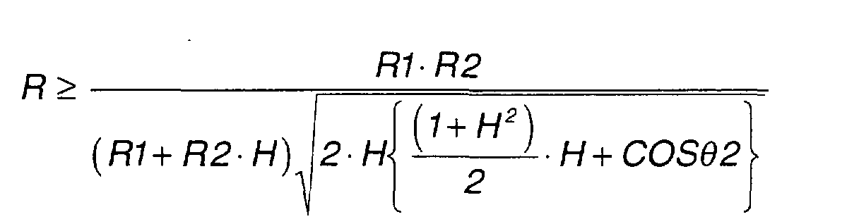
- H =
- tan β1 / tan β2,
- R1 =
- pitch circle radius of the third helical gear,
- R2 =
- pitch circle radius of the fourth helical gear,
- β1 =
- spiral angle of the third helical gear,
- β2 =
- spiral angle of the fourth helical gear, and
- 2 =
- angle subtended by the mesh point of the first helical gear and third helical gear, and the mesh point of the second helical gear and fourth helical gear, with the intermediate shaft as center.
- The details as well as other features and advantages of this invention are set forth in the remainder of the specification and are shown in the accompanying drawings.
-
- FIG. 1 is a schematic cross-sectional view of a vehicle drive train mechanism including a torque transmission device according to this invention.
- FIG. 2 is an enlarged longitudinal sectional view of the torque transmission device.
- FIG. 3 is a schematic diagram of the torque transmission device.
- FIGs. 4A and 4B are a schematic longitudinal sectional view of the torque transmission device describing loads acting on the device.
- FIG. 5 is a perspective view of one of two helical gears with which the torque transmission device is provided, describing a force acting on a tooth surface of the gear.
- FIG. 6 is a side view of the gear describing the force acting on the tooth surface of the gear.
- FIG. 7 is a schematic side view of the torque transmission device describing supporting forces acting on the device when a drive force is transmitted.
- FIG. 8 is a schematic front view of the helical gears describing loads acting on the gears when they transmit the drive force.
- FIG. 9 is a three -dimensional diagram describing the location of the two helical gears and a thrust bearing according to this invention.
- FIGs. 10A-10C are two-dimensional representations of the three-dimensional diagram of FIG. 9.
- FIGs. 11A-11C are two-dimensional diagrams describing the load acting on one of the gears.
- FIG. 12 is a diagram describing a relation between an average radius R of the thrust bearing and an angle 2 subtended by two mesh points of the gears.
-
- Referring to FIG. 1 of the drawings, a vehicle drive train comprises an
electrical transmission 2, adifferential 12 and a torque transmission device interposed therebetween. - The
electrical transmission 2 is provided with two motor/generators - The motor/
generator 20 comprises arotor 20 andstator 21. Therotor 20 is joined to the crankshaft of an engine, not shown, via aninput shaft 3. - The motor/
generator 23 comprises arotor 24 andstator 25. Therotor 24 is joined to a sleeve-shaped output shaft 4 disposed coaxially on the outside of thetransmission input shaft 3. Thestators casing 15. - In the
transmission 2, electric power is generated by the motor/generator 20 due to rotation of theinput shaft 3 driven by the engine, and the generated power drives the motor/generator 23 so as to rotate theoutput shaft 4. The speed ratio is controlled via an inverter, not shown. - The
output shaft 4 is supported in thecasing 15 viabearings bearing holder 26. Anoutput gear 40 is formed on the outer circumference of one end of theoutput shaft 4 on the right-hand side of FIG. 1. Theoutput gear 40 meshes with anidler gear 7 which rotates around anidler shaft 5. - The
idler shaft 5 is disposed parallel to theinput shaft 3 andoutput shaft 4. - Referring to FIG. 2, one end of the
idler shaft 5 is fixed to abracket 29 formed in one piece with the bearingholder 26. The other end of theidler shaft 5 is fixed to acover 16 of thecasing 15 via a fixingmember 17. - A
reduction gear 6 is arranged on theidler shaft 5 so as to rotate together with theidler gear 7. Thereduction gear 6 comprises a sleeve -shapedextension part 6A, and the inner circumference of theidler gear 7 is spline-jointed to the outer circumference of theextension part 6A. Thereduction gear 6 is supported on the outer circumference of theidler shaft 5 byradial bearings retainer 18 is fixed to one end of theextension part 6A. Theretainer 18 is supported on thecover 16 via athrust bearing 10 comprising a needle bearing and a fixingmember 17 fixed to thecover 16. The opposite end of thereduction gear 6 is supported on abracket 29 by athrust bearing 11 comprising a needle bearing. - The
reduction gear 6 meshes with afinal drive gear 13 of the differential 12. The rotation of thefinal drive gear 13 is output to left andright drive shafts 14 via the differential 12. - The
transmission output shaft 4 corresponds to a first rotation shaft, thedrive shafts 14 correspond to a second rotation shaft and theidler shaft 5 corresponds to a third rotation shaft. Theoutput gear 40 corresponds to a first helical gear, thefinal drive gear 13 corresponds to a second helical gear, theidler gear 7 corresponds to a third helical gear and thereduction gear 6 corresponds to a fourth helical gear. - Next, referring to FIG. 3, the tooth trace direction of the
output gear 40,idler gear 7,reduction gear 6 and thefinal drive gear 13, all of which are helical gears, is set as follows. - Specifically, the tooth trace of the
output gear 40 is a right-hand helix while the tooth trace of theidler gear 7 is a left-hand helix. The tooth trace of thereduction gear 6 is a right-hand helix while the tooth trace of thefinal drive gear 13 is a left-hand helix. As a result, when torque is transmitted from theoutput shaft 4 to thedrive shafts 14, a thrust force Ka2 acts on thereduction gear 6 on theidler shaft 5 and a thrust force Ka1 acts on theidler gear 7, both these forces acting toward thecover 16. - Next, referring to FIG. 4A, a moment tending to incline the
idler shaft 5 acts according to the magnitude of the thrust force Ka1 acting on theidler gear 7 and the magnitude of the thrust force Ka2 acting on thereduction gear 6. Thethrust bearing 10 prevents tilt of theidler shaft 5 by generating a reaction force opposing this moment. - The thrust forces Ka1, Ka2 may be extremely different depending on the relation between the meshing position of the
idler gear 7 andoutput gear 40 and the meshing position of thereduction gear 6 andfinal drive gear 13, the spiral angle of the helical teeth of theidler gear 7 andreduction gear 6, or the difference in pitch diameters thereof. - Referring to FIG. 4B, when for example the thrust force Ka1 is much larger than the thrust force Ka2, and the application point of the thrust force Ka1 is situated further outside than the application point of the reaction of the
thrust bearing 10, it is impossible to stop the tilt of theidler shaft 5 only by thethrust bearing 10. - FIGs. 4A and 4B show models describing the relation between the helical gear meshing position and the application point of the reaction exerted by the
thrust bearing 10. In these figures, to simplify the description, theidler shaft 5 is supported as a cantilever and theidler gear 7 andreduction gear 6 are formed in one piece. - In this torque transmission device, tilt of the
idler shaft 5 is prevented by specifying the relation between the helical gear meshing position and the application point of the reaction exerted by the thrust bearing 10 in the following way. - For the purpose of this specification, loads and positional relations are defined as follows.
- As shown in FIGs. 5 and 6, the force acting on the
helical gear - FIGs. 7 - 9 show dynamic models when the
idler shaft 5 is supported on one side by thecover 16 via thethrust bearing 10. - The
idler gear 7 meshes with theoutput gear 40 at a point A, and thereduction gear 6 meshes with thefinal gear 13 at a point B. At the point A, the axial load acting on theidler gear 7 is defined as Ka1, the central load acting on theidler gear 7 is defined as Ks1 and the tangential load acting on theidler gear 7 is defined as Kt1, respectively. At the point B, the axial load acting on thereduction gear 6 is defined as Ka2, the central load acting on thereduction gear 6 is defined as Ks2, and the tangential load acting on thereduction gear 6 is defined as Kt2, respectively. - A load acting on a
radial bearing 9 is defined as Fb, a load acting on theradial bearing 10 is defined as Fa, and a load acting on thethrust bearing 10 is defined as Fc. Further, the center axis of theidler shaft 5 is taken as the Z axis, the axis passing through the mesh point A and the center of theidler shaft 5 is taken as the X axis, and the axis perpendicular to the X axis is taken as the Y axis. - The angle subtended by the mesh point A and the mesh point B at the center of the Z axis, is defined as the angle 2.
- The pitch circle radius of the
idler gear 7 is defined as R1, the pitch circle radius of thereduction gear 6 is defined as R2, the average radius of thethrust bearing 10 is defined as R, the distance from the thrust bearing 10 to theidler gear 7 is defined as Z1, and the distance from the thrust bearing 10 to thereduction gear 6 is defined as Z2. - The pressure angle and the spiral angle of the teeth of the
idler gear 7 are defined as α1 and β1 respectively. The pressure angle and the spiral angle of the teeth of thereduction gear 6 are defined as α2 and β2 respectively. The transmission torque of theidler shaft 5 is defined as T. - Using the above definitions, the loads acting on the
idler shaft 7 are as follows. - The loads acting on the
reduction gear 6 are as follows. - Solving the above equations, considering that the sum of the moments around the X axis, Y axis and Z axis is 0, and the sum of the forces along each axis is also 0, the magnitude and direction of the reaction exerted by the
bearings gears - Here, the condition that the
idler shaft 5 does not tilt is that the application point of the reaction exerted by the thrust bearing 10 on thegears thrust bearing 10. - If the average radius R of the
thrust bearing 10 satisfies the following conditional equation (1), tilt of thethrust shaft 5 is prevented.where, H = tan β1 / tan β2.
- Therefore, if the pitch circle radius R1 of the
idler gear 7, the spiral angle β1, the pitch circle radius R2 of thereduction gear 6 and the spiral angle β2 are set based on the angle 2 to satisfy equation (1), the average radius R of thethrust bearing 10 can be calculated so that theidler shaft 5 does not tilt. - For example, in FIGs. 7 - 9, the conditions are set as follows.
- R1=0.07361 (m)
- β1 =29.3166 (deg)
- R2=0.03215 (m)
- β2 = 27 (deg)
- 2 = 110 (deg)
-
- If these data are substituted in equation (1), R≥0.0262 (m) is obtained.
- If the magnitude of R is set to satisfy this condition, tilt of the
idler shaft 5 can be prevented. For example, if the outer diameter of the thrust bearing 10 (11) is set to 60 mm and the inner diameter is set to 40 mm, this condition will definitely be satisfied. - There is no need to subject the
thrust bearings idler shaft 5 can be prevented while suppressing frictional losses. - Next, referring to FIGs. 10A - 10C and FIGs. 11A - 11C, the angle 2, and the forces and moments exerted by the
reduction gear 6 andidler gear 7 on theidler shaft 5 will be described. - First, the three-dimensional forces shown in FIG. 9 will be split into two-dimensional forces to consider the forces acting on the
idler shaft 5. FIG. 10A shows the forces acting in a plane specified by the Y axis and Z axis. FIG. 10B shows the forces acting on a plane specified by the X axis and Z axis. FIG. 10C shows the forces acting on a plane specified by the X axis and Y axis. - Here, the X axis is set parallel to the load in the central direction acting on the mesh point A of the
idler gear 7, the Y axis is set parallel to the load in the tangential central direction acting on the mesh point A of theidler gear 7, and the Z axis is set parallel to the load in the axial direction acting on the mesh point A of theidler gear 7. - Therefore, the axial components of the tangential load Kt2 and central load Ks2 of the
reduction gear 6 appearing on the planes in FIGs. 10A-10C vary according to the magnitude of the angle 2. - Hence, the load on the
idler shaft 5 is first calculated without including the load of thereduction gear 6. Next, the load acting on theidler shaft 5 due to the load of thereduction gear 6 is calculated. Finally, the total moment acting on theidler shaft 5 is calculated by summing these calculation results. - In this calculation, it is considered that the thrust load acting on the
idler shaft 5 and the moment due to the thrust load are all supported by thethrust bearing 10. - In the calculation, let the sum of the moments around the X axis be ΣMx, the sum of the moments around the Y axis be ΣMy, and the sum of the moments around the Z axis be ΣMz. Further, let the sum of the forces in the X axis direction be ΣFx, the sum of the forces in the Y axis direction be ΣFy, and the sum of the forces in the Z axis direction be ΣFz.
- Let the distance from the thrust bearing 10 to the
radial bearing 8 be Za, and the distance from the thrust bearing 10 to theradial bearing 9 be Zb. - With the above assumptions, the moments and forces on the axes not including the load of the
reduction gear 6 are shown by the following equations (2) - (7). - Next, the load on the
idler shaft 5 due to thereduction gear 6 may be split into the tangential load Kt2, central load Ks2 and axial load Ka2 as shown in FIGs. 11A - 11C. - First, referring to FIG. 11A, the components of the tangential load Kt2 in the X axis, Y axis and Z axis directions are as follows.
- Component in X axis direction = Kt2 · sin 2
- Component in Y axis direction = -Kt2 · cos 2
- Component in Z axis direction = 0
-
- The distances in the X axis, Y axis and Z axis directions from the center of the thrust bearing 10 to the mesh point B of the
reduction gear 6 andfinal drive gear 13 are as follows. - Distance along X axis = R2· cos 2
- Distance along Y axis = R2· sin 2
- Distance along Z axis = Z2
-
- The moments Mx, My, Mz around the X axis, Y axis and Z axis exerted by the tangential load Kt2 on the
idler shaft 5, are as follows. - Mx = -Kt2 · Z2 · cos 2
- My = -Kt2 · Z2 · sin 2
- Mz = - Kt2 · R2
-
- Next, referring to FIG. 11B, the components of the central load Ks2 in the X axis, Y axis and Z axis directions are as follows.
- Component in X axis direction = -Ks2 · cos 2
- Component in Y axis direction = -Kt2 · sin 2
- Component in Z axis direction = 0
-
- The distances in the X axis, Y axis and Z axis directions from the center of the thrust bearing 10 to the mesh point B have already been calculated.
- The moments Mx, My, Mz around the X axis, Y axis and Z axis exerted by the central load Kt2 on the
idler shaft 5, are as follows. - Mx=-Ks2 · Z2 · sin2
- My=-Ks2 · Z2 · cos 2
- Mz = 0
-
- Next, referring to FIG. 11C, the components of the axial load Ka2 in the X axis, Y axis and Z axis directions are as follows.
- Component in X axis direction = 0
- Component in Y axis direction = 0
- Component in Z axis direction = -Ka2
-
- The distances in the X axis, Y axis and Z axis directions from the center of the thrust bearing 10 to the mesh point B have already been calculated.
- The moments Mx, My, Mz around the X axis, Y axis and Z axis exerted by the axial load Ka2 on the
idler shaft 5, are as follows. - Mx=Ks2 · R2 · sin 2
- My=-Ka2 · R2 · cos 2
- Mz= 0
-
- Therefore, the sum of the directional components of the forces and moments exerted by the
reduction gear 6 on theidler shaft 5 are given by the following equations (8) - (13). - Adding equations (8) - (13) representing the moments and forces due to the load of the
reduction gear 6 to equations (2) - (7) representing the calculation results not including the load due to thereduction gear 6, the following equations (14) - (19) are obtained. - Considering that the thrust forces and moments exerted by the
gears idler shaft 5 are supported by thethrust bearing 10, equation (2) can be rewritten as follows. - Similarly, equation (3) can be rewritten as follows.
- Equation (6) can be rewritten as follows.
- Therefore, the following equation (20) is satisfied.
- The average radius R of the
thrust bearing 10 is given by the following equation (21). - Due to the above relations, equations (14) and (15) can be rewritten as the following equations (14A) and (15A).
- Equation (17) can be rewritten as the following equation (22).
- Here, if (Ks1 - Kt2 · sin2 + Ks2 · cos2) in equation (22) is defined as A, equation (22) can be rewritten as equation (22A).
- Next, equation (18) can be rewritten as equation (23).
- Here, if (Kt1 + Kt2 · cos2 + Ks2 · sin2) in equation (23) is defined as B, equation (23) can be rewritten as equation (23A).
- Further, dividing equation (23A) by equation (22A), the following equation (24) is obtained.
- In equation (14A), if (- Kt1 · Z1 - Kt2 · Z2 · cos2 - Ks2 · Z2 · sin2) is defined as C, equation (14A) can be rewritten as equation (14B).
- In equation (15), if (Ks1 · Z1 - Kt2 · Z2 · sin 2 + Ks2 · Z2 · cos2) is defined as D, equation (15A) can be rewritten as equation (15B).
- Substituting equation (22A) into equation (15B), the following equation (15C) is obtained.
- Therefore, the following equation (25) is satisfied.
- Similarly, substituting equation (23A) into equation (14B), the following equation (14C) is obtained.
- Therefore, the following equation (26) is satisfied.
- From equations (25) and (26), the load Fb supported by the
radial bearing 9 is given by the following equation (27). - Further, from equations (22A) and (23A), the load Fa supported by the
radial bearing 10 is given by the following equation (28). - Solving the relational expressions that the sum ΣM of moments around the axes and the sum ΣF of forces in the axial directions are respectively zero, the reactions of the bearings and their directions of action can be calculated.
- Next, equation (20) specifies the relations shown in FIG. 12 concerning the average radius R of the
thrust bearings - Specifically, when the thrust load acting on the idler the
gear 7 and the thrust load acting on thereduction gear 6 are in the same direction as shown in FIG. 3, the average radius R of the thrust bearing 10 (11) is a maximum at 2 = 0, and a minimum at 2 = π (rad). - Here, the average radius R when the thrust loads on the
idler gear 7 andreduction gear 6 are in the same direction, and the average radius R when they are in opposite directions, are equal when the angle 2 is equal to the angle 3. This angle 3 is given by the following equation (29).
- Hence, when the angle 2 of the mesh points A and B is larger than the angle 3 in the range from zero to π (rad), by setting the spiral angle β2 of the
reduction gear 6 and the spiral angle β1 of theidler gear 7 so that the thrust forces act in the same direction, the average radius R of thethrust bearings - Conversely, when the angle 2 at the mesh points A and B is less than the angle 3 within a range from zero to π (rad), by setting the spiral angle β2 of the
reduction gear 6 and the spiral angle β1 of theidler gear 7 so that the thrust forces act in opposite directions, the average radius R of thethrust bearings - The contents of Tokugan 2000-233017, with a filing date of August 1, 2000 in Japan, are hereby incorporated by reference.
- Although the invention has been described above by reference to certain embodiments of the invention, the invention is not limited to the embodiments described above. Modifications and variations of the embodiments described above will occur to those skilled in the art, in light of the above teachings.
- For example, ball bearings or roller bearings may be used for the
radial bearings - The embodiments of this invention in which an exclusive property or privilege is claimed are defined as follows:
Claims (6)
- A torque transmission device, comprising:where,a first rotating shaft (4) supporting a first helical gear (40);a second rotating shaft (14) supporting a second helical gear (13), the second rotating shaft (14) being disposed parallel to the first rotating shaft (4);a rotation body (6,7) comprising a third helical gear (7) which meshes with the first helical gear (40), and a fourth helical gear (6) which meshes with the second helical gear (13);an intermediate shaft (5) which supports the rotation body (6, 7), the intermediate shaft (5) being disposed parallel to the first rotating shaft (4); anda thrust bearing (10, 11) which supports the rotation body (6,7) in a direction along the intermediate shaft (5), the thrust bearing (6, 7) having an average radius R specified by the following equation:
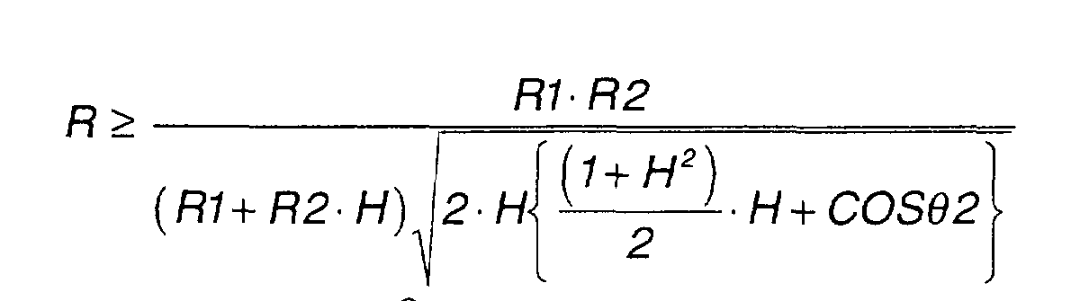
- H =
- tan β1 / tan β2,
- R1 =
- pitch circle radius of the third helical gear (7),
- R2 =
- pitch circle radius of the fourth helical gear (6),
- β1 =
- spiral angle of the third helical gear (7),
- β2 =
- spiral angle of the fourth helical gear (6), and
- 2 =
- angle subtended by the mesh point of the first helical gear (40) and third helical gear (7), and the mesh point of the second helical gear (13) and fourth helical gear, with the intermediate shaft (5) as center.
- The torque transmission device as defined in Claim 1, wherein beta 1 and β2 are set a value which gives a negative value to H, and the angle 2 is set to be less than a predetermined value 3 given by the following equation:where,
 R1 = pitch circle radius of the third helical gear (7), andR2 = pitch circle radius of the fourth helical gear (6).
 - The torque transmission device as defined in Claim 1, wherein beta 1 and β2 are set a value which gives a positive value to H, and the angle 2 is set to be larger than a predetermined value 3 given by the following equation:where,
 R1= pitch circle radius of the third helical gear (7), andR2 = pitch circle radius of the fourth helical gear (6).
 - The torque transmission device as defined in one of Claims 1 through 3, wherein the thrust bearing (10, 11) comprises a needle bearing.
- The torque transmission device as defined in one of Claims 1 through 4, wherein the device further comprises a radial bearing (8, 9) which supports the rotation body (6, 7) on the intermediate shaft (5).
- The torque transmission device as defined in Claim 5, wherein the radial bearing (8, 9) comprises a needle bearing.
Applications Claiming Priority (2)
| Application Number | Priority Date | Filing Date | Title |
|---|---|---|---|
| JP2000233017A JP3856085B2 (en) | 2000-08-01 | 2000-08-01 | Power transmission device for vehicle |
| JP2000233017 | 2000-08-01 |
Publications (2)
| Publication Number | Publication Date |
|---|---|
| EP1177929A2 true EP1177929A2 (en) | 2002-02-06 |
| EP1177929A3 EP1177929A3 (en) | 2003-06-11 |
Family
ID=18725610
Family Applications (1)
| Application Number | Title | Priority Date | Filing Date |
|---|---|---|---|
| EP01118273A Withdrawn EP1177929A3 (en) | 2000-08-01 | 2001-07-30 | Torque transmission device |
Country Status (3)
| Country | Link |
|---|---|
| US (1) | US6666103B2 (en) |
| EP (1) | EP1177929A3 (en) |
| JP (1) | JP3856085B2 (en) |
Cited By (3)
| Publication number | Priority date | Publication date | Assignee | Title |
|---|---|---|---|---|
| WO2009074429A1 (en) * | 2007-12-12 | 2009-06-18 | Zf Friedrichshafen Ag | Electric drive for a mobile vehicle |
| CN104913029A (en) * | 2015-06-16 | 2015-09-16 | 南京高精齿轮集团有限公司 | Herringbone gear pair capable of bearing additional axial force and application of herringbone gear pair to gear box |
| EP3674582A4 (en) * | 2017-08-21 | 2021-04-14 | LG Innotek Co., Ltd. | GEARBOX AND ACTUATOR INCLUDING THE SAID GEARBOX |
Families Citing this family (20)
| Publication number | Priority date | Publication date | Assignee | Title |
|---|---|---|---|---|
| JP4346059B2 (en) * | 2000-09-08 | 2009-10-14 | 本田技研工業株式会社 | Vehicle transmission |
| DE10325647A1 (en) * | 2003-06-06 | 2004-02-05 | Daimlerchrysler Ag | Dual clutch transmission, comprising components all positioned in order to achieve unit of compact size |
| TWI228576B (en) * | 2003-10-29 | 2005-03-01 | Benq Corp | Gear assembly |
| KR100598874B1 (en) * | 2003-11-17 | 2006-07-10 | 현대자동차주식회사 | Automatic transmission |
| US6983990B2 (en) * | 2004-02-03 | 2006-01-10 | L&P Property Management Company | Dual drive power actuator |
| JP2007028883A (en) * | 2005-06-16 | 2007-02-01 | Sumitomo Heavy Ind Ltd | Geared motor and shaft member for the same |
| US7789191B2 (en) * | 2007-04-24 | 2010-09-07 | Sona Koyo Steering Systems Ltd. | Electric power assist module for steering system |
| DE102008013983B3 (en) * | 2008-03-12 | 2009-08-13 | Jahnel-Kestermann Getriebewerke Gmbh & Co. Kg | Method for adjusting a tooth flank position of a toothed wheel, which is frictionally connected to a double helical pinion shaft |
| JP5053314B2 (en) * | 2009-03-10 | 2012-10-17 | 本田技研工業株式会社 | Seat belt retractor |
| SI2284420T1 (en) * | 2009-08-10 | 2012-08-31 | Zf Wind Power Antwerpen Nv | Parallel gear unit for a gearbox for a wind turbine |
| EP2531746B1 (en) | 2010-02-02 | 2014-07-16 | Harrier Technologies Inc. | Improvement in helical gear sets |
| KR101283187B1 (en) | 2010-07-19 | 2013-07-05 | 기아자동차주식회사 | Gear Structure for Transmission |
| US20130068057A1 (en) * | 2011-09-16 | 2013-03-21 | Hamilon Sundstrand Corporation | Idler gear assembly for a generator |
| US10030711B2 (en) | 2013-01-07 | 2018-07-24 | Ford Global Technologies, Llc | Preventing noise from mating spline teeth |
| JP6453700B2 (en) * | 2015-04-20 | 2019-01-16 | Ntn株式会社 | Two-motor vehicle drive device |
| EP3429412B1 (en) * | 2016-03-15 | 2025-05-28 | NIKE Innovate C.V. | Transmission for motorized tensioning system for footwear |
| WO2019142701A1 (en) * | 2018-01-16 | 2019-07-25 | Ntn株式会社 | In-wheel motor drive device |
| JP2019123496A (en) * | 2018-01-16 | 2019-07-25 | Ntn株式会社 | In-wheel motor driving device |
| CN108801639B (en) * | 2018-07-26 | 2024-02-02 | 索特传动设备有限公司 | Bearing test tool and system |
| JP7395380B2 (en) * | 2020-02-17 | 2023-12-11 | キヤノン株式会社 | Drive device and fixing device |
Citations (1)
| Publication number | Priority date | Publication date | Assignee | Title |
|---|---|---|---|---|
| JPH1182653A (en) | 1997-08-29 | 1999-03-26 | Aichi Mach Ind Co Ltd | Continuously variable transmission |
Family Cites Families (12)
| Publication number | Priority date | Publication date | Assignee | Title |
|---|---|---|---|---|
| US1551565A (en) * | 1925-09-01 | Helicai | ||
| US3513715A (en) * | 1967-11-20 | 1970-05-26 | Joseph E Whitfield | Speed changing mechanism |
| US4361058A (en) * | 1980-05-19 | 1982-11-30 | The Falk Corporation | Divided thrust apparatus |
| JPS644783Y2 (en) * | 1980-06-02 | 1989-02-07 | ||
| JP2920250B2 (en) | 1988-03-18 | 1999-07-19 | トヨタ自動車株式会社 | Automatic transmission |
| JP3017759B2 (en) | 1989-11-15 | 2000-03-13 | アイシン・エィ・ダブリュ株式会社 | Bearing lubrication structure for rotating members of automatic transmission |
| US5169370A (en) * | 1991-07-25 | 1992-12-08 | Zexel-Gleason Usa, Inc. | End-thrust design for parallel-axis differential |
| US5339707A (en) * | 1992-12-31 | 1994-08-23 | Arbus William J | Compound automotive transmission for light trucks |
| JP3661296B2 (en) | 1996-08-20 | 2005-06-15 | アイシン・エィ・ダブリュ株式会社 | Automatic transmission for vehicles |
| JP3219016B2 (en) | 1997-03-21 | 2001-10-15 | トヨタ自動車株式会社 | Gear device and power output device including the same |
| JP3473471B2 (en) * | 1999-01-27 | 2003-12-02 | 日産自動車株式会社 | Transmission ratio infinitely variable transmission |
| KR100349319B1 (en) * | 1999-01-27 | 2002-08-21 | 닛산 지도우샤 가부시키가이샤 | Non-finite speed ratio continuously variable transmission |
-
2000
- 2000-08-01 JP JP2000233017A patent/JP3856085B2/en not_active Expired - Fee Related
-
2001
- 2001-07-05 US US09/897,806 patent/US6666103B2/en not_active Expired - Fee Related
- 2001-07-30 EP EP01118273A patent/EP1177929A3/en not_active Withdrawn
Patent Citations (1)
| Publication number | Priority date | Publication date | Assignee | Title |
|---|---|---|---|---|
| JPH1182653A (en) | 1997-08-29 | 1999-03-26 | Aichi Mach Ind Co Ltd | Continuously variable transmission |
Cited By (5)
| Publication number | Priority date | Publication date | Assignee | Title |
|---|---|---|---|---|
| WO2009074429A1 (en) * | 2007-12-12 | 2009-06-18 | Zf Friedrichshafen Ag | Electric drive for a mobile vehicle |
| US8439786B2 (en) | 2007-12-12 | 2013-05-14 | Zf Friedrichshafen Ag | Electric drive for a mobile vehicle |
| CN104913029A (en) * | 2015-06-16 | 2015-09-16 | 南京高精齿轮集团有限公司 | Herringbone gear pair capable of bearing additional axial force and application of herringbone gear pair to gear box |
| EP3674582A4 (en) * | 2017-08-21 | 2021-04-14 | LG Innotek Co., Ltd. | GEARBOX AND ACTUATOR INCLUDING THE SAID GEARBOX |
| US11133726B2 (en) | 2017-08-21 | 2021-09-28 | Lg Innotek Co., Ltd. | Gearbox and actuator |
Also Published As
| Publication number | Publication date |
|---|---|
| EP1177929A3 (en) | 2003-06-11 |
| US20020033061A1 (en) | 2002-03-21 |
| JP2002048221A (en) | 2002-02-15 |
| JP3856085B2 (en) | 2006-12-13 |
| US6666103B2 (en) | 2003-12-23 |
Similar Documents
| Publication | Publication Date | Title |
|---|---|---|
| US6666103B2 (en) | Torque transmission device | |
| EP1992841B1 (en) | Differential apparatus for vehicle | |
| EP0474897B1 (en) | Planetary speed changing device | |
| CN104723860A (en) | Hybrid vehicle driving apparatus | |
| EP3399211A1 (en) | Cycloid speed reducer | |
| CN110154752A (en) | Vehicle propulsion system | |
| US10788097B2 (en) | Friction damper | |
| JP2008298231A (en) | Final reduction gear | |
| EP4141287B1 (en) | Transmission mechanism | |
| US20140243145A1 (en) | Planetary gear device for vehicle power transmission device | |
| CN107664203B (en) | Rotary support structure for planetary gear set of power transmission system | |
| JP2007039000A (en) | Power transmission device for hybrid vehicle | |
| EP1188956A2 (en) | Infinitely variable transmission | |
| US11421766B2 (en) | Gear train and vehicle installing gear train | |
| CN111828550A (en) | Reducers and Robots | |
| EP2246593A1 (en) | Friction roller type power transmission device | |
| US6306059B1 (en) | Infinite speed ratio transmission device | |
| US20240263691A1 (en) | Power transmission device | |
| JP2003127683A (en) | Vehicle drive system | |
| EP1024316A2 (en) | Infinite speed ratio transmission device | |
| CN113412377A (en) | Power transmission device | |
| EP0707161A2 (en) | Differential apparatus | |
| EP1063118B1 (en) | Power train system for a vehicle | |
| JP5434550B2 (en) | Power transmission device | |
| JP5130194B2 (en) | Power transmission device |
Legal Events
| Date | Code | Title | Description |
|---|---|---|---|
| PUAI | Public reference made under article 153(3) epc to a published international application that has entered the european phase |
Free format text: ORIGINAL CODE: 0009012 |
|
| 17P | Request for examination filed |
Effective date: 20010730 |
|
| AK | Designated contracting states |
Kind code of ref document: A2 Designated state(s): AT BE CH CY DE DK ES FI FR GB GR IE IT LI LU MC NL PT SE TR |
|
| AX | Request for extension of the european patent |
Free format text: AL;LT;LV;MK;RO;SI |
|
| PUAL | Search report despatched |
Free format text: ORIGINAL CODE: 0009013 |
|
| AK | Designated contracting states |
Designated state(s): AT BE CH CY DE DK ES FI FR GB GR IE IT LI LU MC NL PT SE TR |
|
| AX | Request for extension of the european patent |
Extension state: AL LT LV MK RO SI |
|
| RIC1 | Information provided on ipc code assigned before grant |
Ipc: 7F 16H 57/02 B Ipc: 7F 16H 1/18 B Ipc: 7B 60K 6/04 A |
|
| AKX | Designation fees paid |
Designated state(s): DE FR GB |
|
| 17Q | First examination report despatched |
Effective date: 20060316 |
|
| STAA | Information on the status of an ep patent application or granted ep patent |
Free format text: STATUS: THE APPLICATION IS DEEMED TO BE WITHDRAWN |
|
| 18D | Application deemed to be withdrawn |
Effective date: 20070630 |