EP1177921A2 - Vehicle attitude control device and relative operating method - Google Patents
Vehicle attitude control device and relative operating method Download PDFInfo
- Publication number
- EP1177921A2 EP1177921A2 EP01118464A EP01118464A EP1177921A2 EP 1177921 A2 EP1177921 A2 EP 1177921A2 EP 01118464 A EP01118464 A EP 01118464A EP 01118464 A EP01118464 A EP 01118464A EP 1177921 A2 EP1177921 A2 EP 1177921A2
- Authority
- EP
- European Patent Office
- Prior art keywords
- vehicle
- shock absorber
- attitude
- regulation strategy
- control device
- Prior art date
- Legal status (The legal status is an assumption and is not a legal conclusion. Google has not performed a legal analysis and makes no representation as to the accuracy of the status listed.)
- Withdrawn
Links
- 238000011017 operating method Methods 0.000 title description 3
- 239000006096 absorbing agent Substances 0.000 claims abstract description 74
- 230000035939 shock Effects 0.000 claims abstract description 72
- 238000013016 damping Methods 0.000 claims abstract description 17
- 238000000034 method Methods 0.000 claims description 22
- 230000009347 mechanical transmission Effects 0.000 claims description 17
- 230000005540 biological transmission Effects 0.000 description 9
- 230000001276 controlling effect Effects 0.000 description 6
- 239000000725 suspension Substances 0.000 description 5
- 230000001133 acceleration Effects 0.000 description 4
- 230000000694 effects Effects 0.000 description 4
- 230000001105 regulatory effect Effects 0.000 description 2
- 230000000712 assembly Effects 0.000 description 1
- 238000000429 assembly Methods 0.000 description 1
- 238000013178 mathematical model Methods 0.000 description 1
- 238000012544 monitoring process Methods 0.000 description 1
Images


Classifications
-
- B—PERFORMING OPERATIONS; TRANSPORTING
- B60—VEHICLES IN GENERAL
- B60G—VEHICLE SUSPENSION ARRANGEMENTS
- B60G17/00—Resilient suspensions having means for adjusting the spring or vibration-damper characteristics, for regulating the distance between a supporting surface and a sprung part of vehicle or for locking suspension during use to meet varying vehicular or surface conditions, e.g. due to speed or load
- B60G17/06—Characteristics of dampers, e.g. mechanical dampers
-
- B—PERFORMING OPERATIONS; TRANSPORTING
- B60—VEHICLES IN GENERAL
- B60G—VEHICLE SUSPENSION ARRANGEMENTS
- B60G2400/00—Indexing codes relating to detected, measured or calculated conditions or factors
- B60G2400/05—Attitude
-
- B—PERFORMING OPERATIONS; TRANSPORTING
- B60—VEHICLES IN GENERAL
- B60G—VEHICLE SUSPENSION ARRANGEMENTS
- B60G2400/00—Indexing codes relating to detected, measured or calculated conditions or factors
- B60G2400/50—Pressure
- B60G2400/51—Pressure in suspension unit
- B60G2400/518—Pressure in suspension unit in damper
-
- B—PERFORMING OPERATIONS; TRANSPORTING
- B60—VEHICLES IN GENERAL
- B60G—VEHICLE SUSPENSION ARRANGEMENTS
- B60G2500/00—Indexing codes relating to the regulated action or device
- B60G2500/10—Damping action or damper
-
- B—PERFORMING OPERATIONS; TRANSPORTING
- B60—VEHICLES IN GENERAL
- B60G—VEHICLE SUSPENSION ARRANGEMENTS
- B60G2800/00—Indexing codes relating to the type of movement or to the condition of the vehicle and to the end result to be achieved by the control action
- B60G2800/01—Attitude or posture control
Definitions
- the present invention relates to a vehicle attitude control device.
- the present invention relates to a device for controlling the attitude of a vehicle equipped with a robot-operated mechanical transmission, to which the following description refers purely by way of example.
- the electronic central control unit can operate either fully automatically, i.e. itself deciding independently when and how to shift gear; or manually, i.e. by performing the commands entered directly by the driver, after first determining they are mechanically compatible.
- robot-operated mechanical transmissions of the above type when effecting any gear shift, produce variations in the attitude of the vehicle, which, albeit of brief duration, may at times impair driving comfort. Such variations are caused by the necessity to release the clutch of the robot-operated mechanical transmission before effecting any gear shift, thus resulting in a sudden fall in the drive torque transmitted to the wheels, and in an unstable attitude of the vehicle.
- robot-operated mechanical transmissions of the above type require a zero, or near-zero, drive torque at the input of the main transmission shaft.
- robot-operated mechanical transmissions of the above type temporarily alter the attitude of the vehicle, producing a longitudinal oscillating or so-called "pitching" movement which the driver finds particularly annoying, especially when the robot-operated mechanical transmission is operating in automatic.
- gear shifting is controlled directly by the electronic central control unit of the transmission, so that the longitudinal oscillating movements of the vehicle occur one after another with no warning, i.e. without allowing the driver to prepare psychologically for the resulting variation in the attitude of the vehicle.
- a vehicle attitude control device comprising a number of electronically controlled shock absorbers, and an electronic central control unit for driving said electronically controlled shock absorbers so as to regulate, instant by instant, the damping capacity of each;
- said electronic central control unit comprises control means for determining when a gear shift is about to be made; selecting means for determining a shock absorber regulation strategy best suited to counteract the onset of attitude variations produced by the pending gear shift; and shock absorber drive means for controlling the electronically controlled shock absorbers in such a manner as to implement the shock absorber regulation strategy selected by the selecting means.
- the present invention also relates to a vehicle attitude control method.
- a method of controlling the attitude of a vehicle equipped with electronically controlled shock absorbers capable of varying damping capacity on command comprising the steps of determining the start of the gear shift procedure; selecting a shock absorber regulation strategy best suited to counteract the onset of attitude variations produced by the pending gear shift; and implementing said regulation strategy when shifting gear.
- Number 1 in Figure 1 indicates as a whole a vehicle attitude control device which can be installed, preferably though not necessarily, on vehicles 2 equipped with a known robot-operated mechanical transmission (not shown).
- Attitude control device 1 comprises a number of electronically controlled shock absorbers 3 preferably, though not necessarily, integrated in the suspensions 4 of vehicle 2; and an electronic central control unit 5 for driving electronically controlled shock absorbers 3 so as to regulate, instant by instant, the damping capacity of each. More specifically, electronic central control unit 5 controls the damping capacity of electronically controlled shock absorbers 3 when making any gear shift, so as to prevent, by eliminating or at least minimizing, any shift-induced variations in attitude.
- vehicle 2 comprises four wheels, each connected to the vehicle body by a respective known fourbar-linkage suspension 4; and attitude control device 1 comprises four electronically controlled shock absorbers 3, each integrated in the spring-shock absorber assembly of a respective suspension 4.
- the spring-shock absorber assemblies are obviously known, and have a first end hinged to one of the movable elements of suspension 4 - in the example shown, the bottom arm of suspension 4 - and a second end hinged to the body of vehicle 2.
- each electronically controlled shock absorber 3 is defined by a known electronically controlled hydraulic shock absorber having at least one electrically controlled shutter valve (not shown) for regulating oil flow into the body of the shock absorber in known manner and so controlling its damping capacity.
- electronic central control unit 5 comprises: a control circuit 6 for determining when a gear shift is about to be made; a storage module 7 in which are memorized a number of regulation strategies by which to regulate the damping capacity of electronically controlled shock absorbers 3; a selection circuit 8 for determining, on the basis of the information detected by control circuit 6, the best shock absorber regulation strategy of all those memorized in storage module 7; and a shock absorber drive circuit 9 for controlling the shutter valve/s of each electronically controlled shock absorber 3 instant by instant, so as to implement the best shock absorber regulation strategy selected by selection circuit 8.
- attitude control device 1 also comprises a given number of acceleration sensors 10 appropriately distributed on vehicle 2, and which provide for measuring, instant by instant, the values of the forces to which vehicle 2 is subjected when running, and for communicating said values to electronic central control unit 5, which is thus able to process and implement a regulation strategy by which to regulate the damping capacity of electronically controlled shock absorbers 3 and restore an optimum attitude of vehicle 2 as quickly as possible.
- electronic central control unit 5 in this case, also comprises a dynamic attitude control circuit 11 for analyzing the signals from acceleration sensors 10 instant by instant, and real-time processing a shock absorber regulation strategy capable of restoring the initial attitude of vehicle 2 as quickly as possible.
- the strategy may be selected from a number of shock absorber regulation strategies - in which case, electronic central control unit 5 comprises a second storage module 12 in which to memorize the strategies - or may be processed on the basis of a mathematical model of the performance of vehicle 2, also memorized in a second storage module 12.
- electronic central control unit 5 also comprises a comparing circuit 13 for determining, instant by instant, which of the two shock absorber regulation strategies selected by selection circuit 8 and attitude control circuit 11 is the more conservative - i.e. provides for a greater damping capacity of electronically controlled shock absorbers 3 - and for implementing said strategy via drive circuit 9.
- storage module 7 and selection circuit 8 of electronic central control unit 5 will only be activated when shifting gear, so as to prevent the onset of any shift-induced longitudinal oscillating movement; whereas attitude control circuit 11, second storage module 12, comparing circuit 13 and drive circuit 9 are active at all times, so as to restore an optimum attitude of vehicle 2 as quickly as possible following any change in the attitude of vehicle 2.
- Control circuit 6 is, obviously, also active at all times, so as to immediately determine the start of the gear shift procedure.
- electronic central control unit 5 acts before and alongside gear shifting by the robot-operated mechanical transmission, to counteract the onset, or minimize at the outset the extent, of any shift-induced longitudinal oscillating movement.
- electronic central control unit 5 acts after any change in the attitude of vehicle 2 has taken place, be it a longitudinal oscillating movement, a transverse oscillating movement, or a combination of both, by driving electronically controlled shock absorbers 3 in such a manner as to restore an optimum attitude of vehicle 2 as quickly as possible.
- electronic central control unit 5 prevents the onset of any variation in the attitude of vehicle 2, and, in the second, counteracts the effects produced by any variation in the attitude of vehicle 2 and attempts to restore an optimum attitude of vehicle 2 as quickly as possible.
- attitude control device 1 also comprises a manual operation selector (not shown) by which the driver of vehicle 2 can communicate the desired type of vehicle performance to electronic central control unit 5. More specifically, in the example shown, the manual selector allows the driver to choose between a standard drive mode, and a sport mode which provides for a more rigid vehicle attitude.
- attitude control device 1 Operation of attitude control device 1 will now be described only as regards the operations performed by electronic central control unit 5 when shifting gear; the attitude control part of its operation when not shifting gear already being known.
- attitude control device 1 comprises acceleration sensors 10, and that electronic central control unit 5 comprises attitude control circuit 11, second storage module 12 and comparing circuit 13.
- attitude control device 1 Operation of attitude control device 1 will also be described assuming electronic central control unit 5 is connected to a known data transmission network 14 (CAN Bus) on vehicle 2.
- control circuit 6 monitors the control signals on data transmission network 14 in search of the control signal or sequence of control signals indicating the start of the gear shift procedure by the robot-operated mechanical transmission.
- electronic central control unit 5 operates by monitoring data transmission network 14 on vehicle 2, in search of the control signal or sequence of control signals indicating the start of the gear shift procedure by the robot-operated mechanical transmission.
- electronic central control unit 5 acquires the signals from acceleration sensors 10 to determine, instant by instant, the forces to which the vehicle is subjected, and, if necessary, processes the shock absorber regulation strategy best suited to restore an optimum attitude of vehicle 2 as quickly as possible.
- electronic central control unit 5 On detecting the control signal or sequence of control signals predicting a gear shift, electronic central control unit 5 sequentially acquires a number of operating parameters of vehicle 2, such as the speed and/or drive torque of the engine; determines whether the gear shift is up or down; and selects, from the various shock absorber regulation strategies, the best one according to the type of gear shift, according to various vehicle operating parameters (such as the drive torque of the engine), and according to the type of attitude set by the driver.
- a number of operating parameters of vehicle 2 such as the speed and/or drive torque of the engine
- determines whether the gear shift is up or down and selects, from the various shock absorber regulation strategies, the best one according to the type of gear shift, according to various vehicle operating parameters (such as the drive torque of the engine), and according to the type of attitude set by the driver.
- Electronic central control unit 5 compares the shock absorber regulation strategy selected to prevent the onset of any shift-induced variation in attitude, with the shock absorber regulation strategy possibly already being implemented to eliminate any other than shift-induced variations in attitude, and executes the more conservative of the two, i.e. the one providing for a greater damping capacity of electronically controlled shock absorbers 3.
- electronic central control unit 5 interrupts the current shock absorber regulation strategy and again executes the shock absorber regulation strategy possibly already being performed, prior to shifting gear, to eliminate any other than shift-induced variations in attitude.
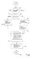
- electronic central control unit 5 acquires the signals on data transmission network 14 of vehicle 2, in search of the control signal or sequence of control signals indicating commencement of the gear shift procedure by the robot-operated mechanical transmission (block 100).
- electronic central control unit 5 performs the operations described below to counteract or at least minimize the onset of any shift-induced longitudinal oscillating movement.
- electronic central control unit 5 first determines, on the basis of various vehicle operating parameters, whether the gear shift is up or down (block 110), and then, in the case of a down shift (DOWN output of block 110), selects the best of the available shock absorber regulation strategies on the basis of various vehicle operating parameters (e.g. engine drive torque) and the type of attitude set by the driver (block 120).
- various vehicle operating parameters e.g. engine drive torque
- type of attitude set by the driver block 120.
- Electronic central control unit 5 compares the shock absorber regulation strategy currently being performed to eliminate other than shift-induced variations in attitude, with the shock absorber regulation strategy just selected to prevent the onset of any variations in attitude induced by the gear shift being performed, and selects the more conservative of the two, i.e. the strategy providing a greater damping capacity of electronically controlled shock absorbers 3 (block 130).
- electronic central control unit 5 executes the more conservative shock absorber regulation strategy (block 140), and interrupts it after a predetermined time interval or on detecting completion of the gear shift procedure. At the end of the regulation strategy selected to counteract the effects of the gear shift, electronic central control unit 5 again executes the shock absorber regulation strategy being performed prior to shifting gear (block 150).
- electronic central control unit 5 determines, on the basis of various vehicle operating parameters, which gear is currently engaged (block 160), and then selects the best of the available regulation strategies on the basis of the gear engaged, other vehicle operating parameters (e.g. engine drive torque), and the type of attitude set by the drive (block 170).
- vehicle operating parameters e.g. engine drive torque
- type of attitude set by the drive block 170
- electronic central control unit 5 compares the shock absorber regulation strategy just selected to prevent the onset of any variations in attitude induced by the gear shift being performed, with the shock absorber regulation strategy currently being performed to eliminate other than shift-induced variations in attitude, and selects the more conservative of the two, i.e. the strategy providing a greater damping capacity of electronically controlled shock absorbers 3 (block 130).
- electronic central control unit 5 executes the more conservative shock absorber regulation strategy (block 140), and interrupts it after a predetermined time interval or on detecting completion of the gear shift procedure.
- electronic central control unit 5 again executes the shock absorber regulation strategy being performed prior to shifting gear (block 150).
- attitude control device 1 any shift-induced variations in the attitude of vehicles 2 equipped with robot-operated mechanical transmissions are eliminated completely, thus improving driving comfort, by effectively regulating the damping capacity of the shock absorbers to counteract any variations even before they occur.
- Attitude control device 1 as described and illustrated herein also has the advantage of being integrated easily and cheaply into known attitude control devices.
- attitude control device 1 and the operating method as described and illustrated herein without, however, departing from the scope of the present invention.
Landscapes
- Engineering & Computer Science (AREA)
- Mechanical Engineering (AREA)
- Vehicle Body Suspensions (AREA)
- Steering Control In Accordance With Driving Conditions (AREA)
- Control Of Electric Motors In General (AREA)
Abstract
Description
Claims (11)
- A vehicle attitude control device (1) comprising a number of electronically controlled shock absorbers (3), and an electronic central control unit (5) for driving said electronically controlled shock absorbers (3) so as to regulate, instant by instant, the damping capacity of each; the attitude control device (1) being characterized in that said electronic central control unit (5) comprises control means (6) for determining when a gear shift is about to be made; selecting means (8) for determining a shock absorber regulation strategy best suited to counteract the onset of attitude variations produced by the pending gear shift; and shock absorber drive means (9) for controlling the electronically controlled shock absorbers (3) in such a manner as to implement the shock absorber regulation strategy selected by the selecting means (8).
- A vehicle attitude control device as claimed in Claim 1, wherein said electronic central control unit (5) comprises storage means (7) in which are memorized a number of strategies by which to regulate the damping capacity of the electronically controlled shock absorbers (3); the selecting means (8) selecting the best strategy by which to regulate the electronically controlled shock absorbers (3) from those memorized in the storage means (7) and on the basis of various operating parameters of the vehicle (2).
- A vehicle attitude control device as claimed in Claim 2, characterized by comprising a number of sensors (10) for determining the values of the forces to which the vehicle (2) is subjected when running, and for communicating said values to the electronic central control unit (5).
- A vehicle attitude control device as claimed in Claim 3, wherein the electronic central control unit (5) comprises dynamic attitude control means (11) for analyzing the signals from said sensors (10) to process a shock absorber regulation strategy which, in the presence of variations in the attitude of the vehicle (2), is capable of restoring the initial attitude of the vehicle (2) as quickly as possible.
- A vehicle attitude control device as claimed in Claim 4, wherein the electronic central control unit (5) comprises comparing means (13) for determining which, of the regulation strategy selected by the selecting means (8) and the regulation strategy selected by the dynamic attitude control means (11), is the more conservative, and for implementing said strategy via the shock absorber drive means (9).
- A vehicle attitude control device as claimed in Claim 5, wherein the comparing means (13) determine which, of the regulation strategy selected by the selecting means (8) and the regulation strategy selected by the dynamic attitude control means (11), provides for the greater damping capacity of the various electronically controlled shock absorbers (3), and implement said strategy via the shock absorber drive means (9).
- A vehicle attitude control device as claimed in any one of the foregoing Claims, wherein said vehicle (2) is equipped with a robot-operated mechanical transmission.
- A method of controlling the attitude of a vehicle (2) equipped with electronically controlled shock absorbers (3) capable of varying damping capacity on command; the method being characterized by comprising the steps of determining the start of the gear shift procedure; selecting a shock absorber regulation strategy best suited to counteract the onset of attitude variations produced by the pending gear shift; and implementing said regulation strategy when shifting gear.
- A method as claimed in Claim 8, wherein said step of selecting the best shock absorber regulation strategy comprises the step of determining the type of gear shift about to be performed.
- A method as claimed in Claim 9, wherein said step of selecting the best shock absorber regulation strategy comprises the step of selecting a shock absorber regulation strategy from a number of possible regulation strategies, on the basis of the type of gear shift about to be performed, and on the basis of other operating parameters of the vehicle (2).
- A method as claimed in Claim 10, wherein said step of selecting the best shock absorber regulation strategy comprises the step of comparing the shock absorber regulation strategy relative to the gear shift, with the shock absorber regulation strategy possibly already being implemented, and implementing the more conservative of the two.
Applications Claiming Priority (2)
| Application Number | Priority Date | Filing Date | Title |
|---|---|---|---|
| IT2000BO000476A ITBO20000476A1 (en) | 2000-08-01 | 2000-08-01 | MOTOR VEHICLE STRUCTURE CONTROL DEVICE AND RELATED OPERATING METHOD. |
| ITBO000476 | 2000-08-01 |
Publications (2)
| Publication Number | Publication Date |
|---|---|
| EP1177921A2 true EP1177921A2 (en) | 2002-02-06 |
| EP1177921A3 EP1177921A3 (en) | 2002-10-23 |
Family
ID=11438666
Family Applications (1)
| Application Number | Title | Priority Date | Filing Date |
|---|---|---|---|
| EP01118464A Withdrawn EP1177921A3 (en) | 2000-08-01 | 2001-07-31 | Vehicle attitude control device and relative operating method |
Country Status (3)
| Country | Link |
|---|---|
| US (1) | US6533293B2 (en) |
| EP (1) | EP1177921A3 (en) |
| IT (1) | ITBO20000476A1 (en) |
Cited By (2)
| Publication number | Priority date | Publication date | Assignee | Title |
|---|---|---|---|---|
| DE102005001506A1 (en) * | 2005-01-13 | 2006-07-27 | Zf Friedrichshafen Ag | Method and device for increasing driving comfort and shortening the shift time |
| EP3069907A1 (en) * | 2015-03-19 | 2016-09-21 | Honda Motor Co., Ltd. | Suspension controlling apparatus for vehicle |
Families Citing this family (1)
| Publication number | Priority date | Publication date | Assignee | Title |
|---|---|---|---|---|
| GB2406548A (en) * | 2003-10-03 | 2005-04-06 | Trelleborg Ab | Air suspension system |
Family Cites Families (5)
| Publication number | Priority date | Publication date | Assignee | Title |
|---|---|---|---|---|
| US4586728A (en) | 1983-02-28 | 1986-05-06 | Mazda Motor Corporation | Vehicle suspension means having variable suspension characteristics |
| EP0425199B1 (en) | 1989-10-27 | 1996-06-19 | Hitachi, Ltd. | Motor vehicle control system and control unit thereof |
| US5475596A (en) * | 1991-05-20 | 1995-12-12 | General Motors Corporation | Full car semi-active suspension control based on quarter car control |
| DE4210536A1 (en) | 1992-03-31 | 1993-10-07 | Fichtel & Sachs Ag | Suspension damping characteristic controller for motor vehicle - uses stored values of transmission ratio with allowance for jerky re-engagement of clutch after change of gear |
| US5941920A (en) * | 1997-11-12 | 1999-08-24 | Case Corporation | Control of an active suspension system for a work vehicle based upon a parameter of another vehicle system |
-
2000
- 2000-08-01 IT IT2000BO000476A patent/ITBO20000476A1/en unknown
-
2001
- 2001-07-27 US US09/915,767 patent/US6533293B2/en not_active Expired - Lifetime
- 2001-07-31 EP EP01118464A patent/EP1177921A3/en not_active Withdrawn
Non-Patent Citations (1)
| Title |
|---|
| None |
Cited By (2)
| Publication number | Priority date | Publication date | Assignee | Title |
|---|---|---|---|---|
| DE102005001506A1 (en) * | 2005-01-13 | 2006-07-27 | Zf Friedrichshafen Ag | Method and device for increasing driving comfort and shortening the shift time |
| EP3069907A1 (en) * | 2015-03-19 | 2016-09-21 | Honda Motor Co., Ltd. | Suspension controlling apparatus for vehicle |
Also Published As
| Publication number | Publication date |
|---|---|
| EP1177921A3 (en) | 2002-10-23 |
| ITBO20000476A0 (en) | 2000-08-01 |
| US20020024186A1 (en) | 2002-02-28 |
| US6533293B2 (en) | 2003-03-18 |
| ITBO20000476A1 (en) | 2002-02-01 |
Similar Documents
| Publication | Publication Date | Title |
|---|---|---|
| US4922427A (en) | Combined power steering and variable suspension control arrangement | |
| KR100806515B1 (en) | Apparatus and method for changing the stability level of the gear shift in the automatic transmission of a vehicle | |
| US6684143B2 (en) | Method for controlling an automatic transmission and controller suitable for such a method | |
| EP2478265B1 (en) | Determination of one or more gearshift points | |
| EP0130794B1 (en) | Electronic control method for vehicles | |
| JP3987722B2 (en) | Control device for automobile drive train | |
| US5478293A (en) | Automatic transmission control system for motor vehicle | |
| US6085140A (en) | Shift control method and system for an automatic transmission | |
| CN103758995A (en) | Braking kick-down control method of double clutch automatic transmission | |
| US5107723A (en) | Select shock attenuation arrangement for an automatic automotive transmission | |
| GB2470192A (en) | Controlling an active vehicle subsystem | |
| US20050126321A1 (en) | Motor vehicle, control unit, driving force transmission system, and motor vehicle control method | |
| US6622581B2 (en) | Apparatus and method for controlling an automatic transmission | |
| US7370548B2 (en) | Method for controlling and regulating a transmission brake in an automatic motor vehicle transmission | |
| US5754969A (en) | Automatic transmission system with lock-up clutch | |
| US6976935B2 (en) | Method and apparatus for operating a motor vehicle | |
| US6533293B2 (en) | Vehicle attitude control device and relative operating method | |
| EP2478267B1 (en) | System for control of gearshift points | |
| US6553306B2 (en) | System for controlling engine braking in a vehicle driveline | |
| JP4301962B2 (en) | Method and apparatus for controlling the operation of a vehicle drive train having an output branching transmission device having a plurality of continuously variable gear ratio regions and a drive motor | |
| JP3579725B2 (en) | Shift control method for upshift of automatic transmission for vehicle | |
| US20050143223A1 (en) | Method for reducing shift shock of automatic vehicle transmission by engine torque reduction control | |
| US20010056007A1 (en) | Shift control method for automatic transmission | |
| US5389052A (en) | Method of regulating and controlling shifting of gears in an automatic transmission to enhance comfort | |
| US7131931B2 (en) | Gearbox control system |
Legal Events
| Date | Code | Title | Description |
|---|---|---|---|
| PUAI | Public reference made under article 153(3) epc to a published international application that has entered the european phase |
Free format text: ORIGINAL CODE: 0009012 |
|
| AK | Designated contracting states |
Kind code of ref document: A2 Designated state(s): AT BE CH CY DE DK ES FI FR GB GR IE IT LI LU MC NL PT SE TR |
|
| AX | Request for extension of the european patent |
Free format text: AL;LT;LV;MK;RO;SI |
|
| PUAL | Search report despatched |
Free format text: ORIGINAL CODE: 0009013 |
|
| AK | Designated contracting states |
Kind code of ref document: A3 Designated state(s): AT BE CH CY DE DK ES FI FR GB GR IE IT LI LU MC NL PT SE TR |
|
| AX | Request for extension of the european patent |
Free format text: AL;LT;LV;MK;RO;SI |
|
| RIC1 | Information provided on ipc code assigned before grant |
Free format text: 7B 60G 17/015 A, 7B 60G 17/06 B, 7B 60K 41/28 B |
|
| 17P | Request for examination filed |
Effective date: 20030422 |
|
| AKX | Designation fees paid |
Designated state(s): DE ES FR GB SE |
|
| 17Q | First examination report despatched |
Effective date: 20070626 |
|
| STAA | Information on the status of an ep patent application or granted ep patent |
Free format text: STATUS: THE APPLICATION IS DEEMED TO BE WITHDRAWN |
|
| 18D | Application deemed to be withdrawn |
Effective date: 20080108 |